Note: Descriptions are shown in the official language in which they were submitted.
CA 02735619 2011-03-31
SYSTEM, METHOD AND APPARATUS FOR PROTECTING DOWNHOLE
COMPONENTS FROM SHOCK AND VIBRATION
BACKGROUND OF THE INVENTION
Field of the Disclosure
[00011 The present invention relates in general to protecting downhole
components from
shock and vibration while drilling a well and, in particular, to a system,
method and
apparatus for protecting measurement while drilling (MWD) equipment from shock
and
vibration.
Description of the Related Art
[0002] Some oil and gas exploration and production companies use vibrating
devices
known as agitators to increase penetration rates while drilling wells.
Agitators typically
operate or reciprocate between about 12 and 26 hertz during drilling
operations, and
constantly vibrate at these frequencies. Accordingly, agitators provide
additional shock
and vibration throughout the drill string that improve drilling performance.
However,
these devices can cause damage to or the failure of the downhole components,
such as the
sensitive electronic components of MWD systems. Moreover, the equipment may be
subjected to high temperatures in the range of 150 C as well as g-force
vibration and
shock on the order of 100 g in amplitude.
[0003] Shock absorbing systems, such as snubbers, have been added to drill
strings to
better protect MWD systems. Some conventional snubbers are silicone or
elastomer-
based and have a relatively high natural frequency. These systems also tend to
be over-
damped and are so stiff that they have virtually no shock absorbing
capability. Thus,
improvements in snubbers for MWD equipment would be desirable.
1
CA 02735619 2011-03-31
SUMMARY
[0004] Embodiments of a system, method and apparatus for protecting MWD
equipment
from shock and vibration are disclosed. In some embodiments, a downhole tool
assembly comprises a component that is sensitive to shock and vibration; a
reciprocating
element coupled to the component, the reciprocating element having an axial
internal
passage and an outer surface; a housing having an internal axial bore for
receiving the
reciprocating element for axial reciprocal motion therein; a retainer mounted
to the
housing and sealing the housing between the component and the reciprocating
element; a
first spring located between the housing and the reciprocating element; a
second spring
located between the reciprocating element and the retainer; a first
reciprocating seal
located between the reciprocating element and the housing; a second
reciprocating seal
located between the connector and the retainer; a fluid contained by the
reciprocating
seals inside the housing; and the reciprocating element permits a limited
amount of fluid
to flow between sides thereof.
[00051 In other embodiments, a snubber shock assembly may comprise a housing
having
an axis and an axial passage; a bushing mounted in the axial passage of the
housing, the
bushing having a piston bore and an outer surface; a piston located in the
piston bore of
the bushing and having a boss received in the axial passage for axial
reciprocal motion
therein, and the boss permits fluid flow between axial sides of the boss; a
first spring
located between the boss of the piston and the bushing; a tube mounted to the
piston and
extending axially therefrom opposite the bushing for axial motion with the
piston, and a
tool mount that is adapted to be mounted to a tool component; a retainer
mounted to the
housing and having a retainer bore that receives the tube such that the tube
is axially
movable relative to the retainer; and a second spring located between the boss
of the
piston and the retainer.
[00061 In still other embodiments, an agitator drilling assembly may comprise
a drill
string; an agitator mounted in the drill string to vibrate and increase
penetration rate while
drilling; a MWD tool having a plurality of components mounted in the drill
string; and
2
CA 02735619 2011-03-31
snubber shock assemblies mounted in the drill string between at least some of
the
components of the MWD tool such that the snubber shock assemblies are mounted
inside
the MWD tool, and said at least some of the components float axially and are
protected
from shock and vibration.
[0007] Embodiments of methods of protecting a component from shock and
vibration
while drilling a well may comprise drilling a well with a drill string;
operating the
component during the drilling of the well; vibrating the component at a
vibration
frequency; and protecting the component from shock and vibration at a natural
frequency
that is less than the vibration frequency.
[0008] The foregoing and other objects and advantages of these embodiments
will be
apparent to those of ordinary skill in the art in view of the following
detailed description,
taken in conjunction with the appended claims and the accompanying drawings.
BRIEF DESCRIPTION OF THE DRAWINGS
[0009] So that the manner in which the features and advantages of the
embodiments are
attained and can be understood in more detail, a more particular description
may be had
by reference to the embodiments thereof that are illustrated in the appended
drawings.
However, the drawings illustrate only some embodiments and therefore are not
to be
considered limiting in scope as there may be other equally effective
embodiments.
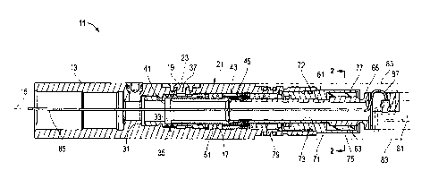
[0010] FIG. 1 is a sectional side view of one embodiment of a snubber
assembly;
[0011] FIG. 2 is a sectional end view of an embodiment of the snubber assembly
of FIG.
1, taken along the line 2-2 of FIG. 1;
[0012] FIG. 3 is a schematic sectional view of a well having an embodiment of
a drill
string with MWD and snubber assemblies; and
[0013] FIG. 4 is an enlarged, partially exploded sectional view of a portion
of the drill
string of FIG. 3.
3
CA 02735619 2011-03-31
[0014] The use of the same reference symbols in different drawings indicates
similar or
identical items.
DETAILED DESCRIPTION
[0015] Embodiments of a system, method and apparatus for protecting MWD
equipment
from shock and vibration are disclosed. For example, FIGS. I and 2 illustrate
one
embodiment of snubber shock assembly 11. Snubber shock assembly 11 may
comprise a
housing 13 having an axis 15, an axial passage 17, a fill port 19 extending
from an
exterior 21 of the housing 13 to the axial passage 17, and an fluid fill cover
23 mounted
and sealed to the fill port 19 as shown.
[00161 A bushing or seal housing 31 may be mounted in and coaxial with the
axial
passage 17 of the housing 13. The seal housing has a piston bore 33 and an
outer surface
35, and at least a portion 37 of the outer surface 35 may be recessed adjacent
the fill port
19.
[0017] The snubber shock assembly 11 may further comprise a piston 41 that is
hollow
and extends into the piston bore 33 of the seal housing 31 for coaxial
reciprocal motion
therein. In some embodiments, the piston has an axial travel range of
approximately one
inch (e.g., +/- one-half inch). The piston 41 has a boss 43 that is axially
external to the
seal housing 31 and is received in the axial passage 17 of the housing 13. The
boss 43
may have means for allowing a limited amount of fluid to bypass the piston.
For
example, at least one damping jet 45 (e.g., two shown) may extend through boss
43 in an
axial direction for permitting fluid to flow therethrough to either axial side
of the boss 43
in the axial passage 17. The damping jets 45 in the piston 41 allow fluid to
pass through
and control the damping ratio in the system. Alternatively, a small radial
separation
between the boss and the axial passage may be used to permit fluid flow around
the boss.
A first spring 51 surrounds a portion of the piston 41 and is located between
the boss 43
of the piston and the seal housing 31.
4
CA 02735619 2011-03-31
100181 In some embodiments, a piston tube or tube 61 that is hollow is
threaded to the
piston 41 and extends axially therefrom opposite the seal housing 31 for axial
motion
with the piston 41. The tube 61 may comprise a spline on one end (right side
of FIG. 1)
with a plurality of tube ribs 63 (FIG. 2) extending in an axial direction and
protruding
radially therefrom. A tool mount 65 is axially external to a retainer 71. The
tool mount
65 is adapted to be mounted to a component 81 of a measurement while drilling
(MWD)
tool, such as a power supply (e.g., battery), sensor, and/or transmitter. The
component 81
typically is located inside a pressure barrel 83, which is threaded and sealed
to the
housing 13.
100191 The piston retainer or retainer 71 is mounted in (e.g., threaded to)
and coaxial
with the axial passage 17 of the housing 13. The retainer 71 has a retainer
bore 73 that
receives the tube 61 and the tube 61 is axially movable relative to the
retainer 71. The
seal housing 31 and the retainer may both be threaded and sealed to the
housing 13,
which has fluid (e.g., oil) in the axial passage 17.
100201 As best shown in FIG. 2, a keyway 75 may be located in the retainer
bore 73 and
is complementary to and receives the tube ribs 63 of the spline of the tube
61. A
compliant bushing 77 (e.g., an elastomeric material such as rubber) is mounted
between
the keyway 75 and tube ribs 63 of the spline to dampen torsional shock
therebetween.
The keyway 75 may comprise a plurality of keyway ribs 76 that extend
longitudinally in
the axial direction and protrude radially inward from the keyway 75. In some
embodiments, the keyway ribs 76 have radially innermost ends located at a
first radial
distance R1 from the axis 15. The tube ribs 63 have radially outermost ends
located at a
second radial distance R2 from the axis 15, which is greater than the first
radial distance
R1. This design physically limits the torsional range of motion of tube ribs
63, tube 61
and piston 41.
[00211 A second spring 79 may be provided to surround a portion of the tube 61
and
located between the boss of the piston and the retainer. For example, the
first and second
springs 51, 79 may comprise wave springs, such as ReduxTM wave springs, and
may be
mounted in parallel.
CA 02735619 2011-03-31
[0022] A cable 85 extends through the housing 13, seal housing 31, piston 41,
tube 61
and the retainer 71. The cable may have a connector 87 (e.g., an MDM
connector) that is
mounted to the tube 61 external of the housing 13 and the retainer 71 at the
tool mount
65. The connector 87 is adapted to be connected to the MWD component 81 as
shown in
FIG. 1.
[0023] The component 81 (e.g., battery, electronics, etc.) may be connected to
the
snubber laterally as opposed to axially so that the stresses caused by axial
vibrations in
the connecting screws are seen as shear rather than tension. Some conventional
designs
bolt the tools together axially, but the lateral arrangement is more stable as
well as being
easier to service. In operation, several snubbers may be used in a single
downhole
assembly to insulate several components as desired.
[0024] In operation, the axial passage 17 may be filled with fluid (e.g., oil)
through the
fill port 19. Prior to filling, the snubber shock assembly 11 and fluid may be
immersed in
an oil bath and heated to a temperature of about 175 C. Thereafter, the fluid
fill cover 23
may be mounted and sealed to the fill port 19 while the assembly is still
submerged.
Appropriate seals are provided between these various components.
[0025] The shock absorber has no accumulator inside so an allowance for
thermal
expansion of the oil is desirable. Most wells are drilled with temperatures
exceeding
80 C, so allowance for thermal expansion helps the shock absorber avoid
hydraulic lock
up as the internal pressure increases. Incorporating the oil filling process
by filling up the
shock absorber while it is completely submerged in oil and heated the prior to
being
plugged allows the oil to expand. Once the desired temperature is reached the
assembly
is plugged, sealed and allowed to cool, leaving a small air gap inside.
[0026] To protect MWD components from shock and vibration, the snubber shock
assembly 11 may be slightly under damped and have a natural frequency of less
than
about 10 Hz. For example, the natural frequency may be about 3 to 9 Hz. Since
the
vibration frequency range of agitators is known, a mechanical spring used by
the shock
absorber may be selected whose natural frequency was outside of that range.
These
springs help ensure that the snubber does not operate at the same resonant
frequency as
6
CA 02735619 2011-03-31
4
the agitators, which can cause significant damage to the MWD electronics and
batteries
while drilling.
100271 As an example, the mass of a suspended battery or electronics device is
about 8
pounds or 3.6 kg. To achieve a natural frequency of less than 10 Hz and
conform to the
small volume required of this shock absorber, wave springs were selected.
Placing two
wave springs in parallel with a 3.6 kg weight yields a natural frequency of
about 8.77 Hz.
The springs are small enough to fit inside an inner diameter of about 1.2
inches, but also
allow an inner diameter of about 0.625 inches, which is large enough to permit
a
connector and a wiring assembly to fit therethrough. This design also permits
proper
sealing around the springs to keep the oil chamber separated from the wiring
channel
while maintaining structural integrity. In some embodiments, the overall
length of
snubber shock assembly 11 is approximately 5 inches, with an outer diameter of
about
1.5 inches.
[00281 While an under-damped system demonstrates an increase in vibration as
the input
frequency is close to the natural frequency, at higher input frequencies the
measured
oscillation is less than what would be seen in an over-damped system. In the
present
example, the natural frequency was kept very low so that virtually any input
would be
above the natural frequency. This design has the benefit of reducing vibration
on the
order of 50% compared to conventional snubbers.
100291 Another obstacle to overcome in snubber design is friction. Shock
absorbers that
use viscous damping are beneficial because they absorb even small impacts
quite well.
There is almost always friction damping involved in these devices, but the
problem with
the friction component is that its effects are greater at low impact
amplitudes and low
masses. In general, a device frictionally "sticks" at its current position
until a significant
impact breaks the static friction to initiate movement. The seals need to be
tight enough
to prevent leaking but low enough to avoid excessive friction.
[00301 For example, one embodiment of a seal 72 for sealing between the
housing 13 and
retainer 71 is energized by a canted coil spring. Canted coil springs provide
a constant
rate as they are compressed. This design maintains enough pressure to seal and
maintain
7
CA 02735619 2011-03-31
that same sealing pressure over a large range of tolerances or wear diameters
without
having to overcompensate and use too much pressure (and thus friction) when
the
tolerances are tight. In some embodiments, the seal is a plastic material that
is bonded to
the metal canted spring, which means that the seal is very structurally sound.
In addition,
it may be seated in a recess in one of the components to avoid deformation
during
installation.
[00311 FIGS. 3 and 4 depict one embodiment of a system used in protecting
components
from shock and vibration while drilling a well. FIG. 3 depicts a well 101
having an
embodiment of a drill string 103 with MWD and snubber shock assemblies 11.
FIG. 4 is
an enlarged, partially exploded sectional view of a portion of the drill
string 103 of FIG.
3. Drill string 103 may include a plurality of connected joints of drill
collars 104 that
house an agitator 105 coupled to an MWD tool 107 having electronics 109 that
are
protected by a snubber shock assembly 11 a. Another snubber shock assembly 11
b is
connected to and protects a battery stave 111 further downhole. A second
battery stave
113 is supported by snubber shock assembly 11 c, and a sensor 115 is protected
by
snubber shock assembly l Id. Other power supplies (e.g., alternators, etc.)
and
components (e.g., transmitters, etc.) also be employed and protected by this
system. In
some embodiments, one snubber shock assembly is secured to one axial end of a
component to be protected, and a shock cord is secured to the other axial end
of the
protected component such that it "floats" axially within the drill string. A
drill bit 117 is
located on the lower end of the drill string 103.
[00321 Embodiments of the snubber shock assembly provide a significant
reduction in
the shock experienced by the components that they protect. For example, some
initial
measurements of damping capability yielded a 92% reduction in the shock felt
from
small (e.g., 0.75-inch) transient inputs. By comparison, conventional snubbers
such as
silicone dampers achieved no greater than a 30% reduction in shock.
[00331 In some embodiments, a downhole tool assembly comprises a component
that is
sensitive to shock and vibration; a reciprocating element coupled to the
component, the
reciprocating element having an axial internal passage and an outer surface; a
housing
8
CA 02735619 2011-03-31
f
having an internal axial bore for receiving the reciprocating element for
axial reciprocal
motion therein; a retainer mounted to the housing and sealing the housing
between the
component and the reciprocating element; a first spring located between the
housing and
the reciprocating element; a second spring located between the reciprocating
element and
the retainer; a first reciprocating seal located between the reciprocating
element and the
housing; a second reciprocating seal located between the connector and the
retainer; a
fluid contained by the reciprocating seals inside the housing; and the
reciprocating
element permits a limited amount of fluid to flow between sides thereof.
100341 The downhole tool assembly may further comprise a cable with a
connector
extending through the housing, reciprocating element and retainer, and the
connector is
connected to the component. The component may comprise at least one component
of a
measurement while drilling (MWD) tool. The reciprocating element may be under
damped and has a natural frequency of less than about 10 Hz. The natural
frequency may
be about 3 to 9 Hz.
[00351 In other embodiments, a downhole tool assembly for measurement while
drilling
(MWD) a well comprises an MWD component; a reciprocating element coupled to
the
MWD component, the reciprocating element has an axial passage and an outer
surface
comprising a small diameter and a large diameter; a connector that couples the
MWD
component to the reciprocating element, the connector having an outer surface
with a
diameter substantially equal to the small diameter of the reciprocating
element; a housing
having an axial bore for receiving the reciprocating element for axial
reciprocal motion
therein; a retainer mounted to the housing and having an axial bore for
receiving the
connector outer surface; a first spring on the small diameter of the
reciprocating element
and located between a shoulder of the axial bore of the housing and a face of
the
reciprocating element; a second spring on the connector and located between
another face
of the reciprocating element and a face of the retainer; a first reciprocating
seal between
the small diameter of the reciprocating element and the axial bore of the
housing; a
second reciprocating seal between the connector and the retainer; a fluid
contained by the
reciprocating seals inside of the housing; and the reciprocating element
allows a limited
9
CA 02735619 2011-03-31
amount of fluid to flow between axial sides of the large diameter in the axial
bore of the
housing.
100361 The reciprocating element may comprise damping jets extending
therethrough to
permit fluid flow between axial sides of the reciprocating element. The
housing may
further comprise a fill port extending from an exterior of the housing to the
axial bore,
and a fluid fill cover mounted and sealed to the fill port. The axial bore may
be filled
with fluid through the fill port, and the downhole tool assembly and fluid are
at a
temperature of about 1750 C when the fluid fill cover is mounted and sealed to
the fill
port. The downhole tool assembly may further comprise a cable with an
electrical
connector extending through the housing, reciprocating element, connector and
retainer,
the electrical connector is mounted to the connector external of the housing
and the
retainer, and the electrical connector is connected to the MWD component. The
MWD
component may comprise at least one of a power supply, sensor, and
transmitter.
100371 The downhole tool assembly may be under damped and has a natural
frequency of
less than about 10 Hz. The natural frequency may be about 3 to 9 Hz. The first
and
second springs may be wave springs that are mounted in parallel. The connector
may
have a spline with plurality of ribs extending in an axial direction and
protruding radially
therefrom, the retainer has a keyway that is complementary to and receives the
spline,
and a compliant bushing is mounted between the keyway and the spline to dampen
torsional shock. The keyway may comprise a plurality of keyway ribs extending
in an
axial direction and protruding radially inward from the keyway. The keyway
ribs may
have innermost ends located at a first radial distance from the axis, and the
ribs have
outermost ends located at a second radial distance from the axis that is
greater than the
first radial distance.
100381 In still other embodiments, a snubber shock assembly may comprise a
housing
having an axis and an axial passage; a bushing mounted in the axial passage of
the
housing, the bushing having a piston bore and an outer surface; a piston
located in the
piston bore of the bushing and having a boss received in the axial passage for
axial
reciprocal motion therein, and the boss permits fluid flow between axial sides
of the boss;
CA 02735619 2011-03-31
a first spring located between the boss of the piston and the bushing; a tube
mounted to
the piston and extending axially therefrom opposite the bushing for axial
motion with the
piston, and a tool mount that is adapted to be mounted to a tool component; a
retainer
mounted to the housing and having a retainer bore that receives the tube such
that the
tube is axially movable relative to the retainer; and a second spring located
between the
boss of the piston and the retainer. The snubber shock assembly may comprise
other
elements and features as described herein.
[0039] In another embodiment, the snubber shock assembly comprises a housing
having
an axis, an axial passage, a fill port extending from an exterior of the
housing to the axial
passage, and an fluid fill cover mounted and sealed to the fill port; a seal
housing
mounted in and coaxial with the axial passage of the housing, the seal housing
having a
piston bore and an outer surface, and at least a portion of the outer surface
is recessed
adjacent the fill port; a piston that is hollow extending into the piston bore
of the seal
housing for axial reciprocal motion therein, the piston having a boss external
to the seal
housing and received in the axial passage, the boss having a damping jet
extending
therethrough in an axial direction for permitting fluid to flow therethrough
to either axial
side of the boss; a first spring surrounding a portion of the piston and
located between the
boss of the piston and the seal housing; a tube that is hollow threaded to the
piston and
extending axially therefrom opposite the seal housing for axial motion with
the piston,
the tube having a spline with a plurality of tube ribs extending in an axial
direction and
protruding radially therefrom, and a tool mount that is adapted to be mounted
to a
component of a measurement while drilling (MWD) tool; a retainer mounted in
and
coaxial with the axial passage of the housing, the retainer having a retainer
bore that
receives the tube and the tube is axially movable relative to the retainer, a
keyway that is
complementary to and receives the spline of the tube, and a compliant bushing
mounted
between the keyway and spline to dampen torsional shock; and a second spring
surrounding a portion of the piston tube and located between the boss of the
piston and
the retainer. The snubber shock assembly may comprise other elements and
features as
described herein.
11
CA 02735619 2011-03-31
100401 In still other embodiments, an agitator drilling assembly may comprise
a drill
string; an agitator mounted in the drill string to vibrate and increase
penetration rate while
drilling; a MWD tool having a plurality of components mounted in the drill
string; and
snubber shock assemblies mounted in the drill string between at least some of
the
components of the MWD tool such that the snubber shock assemblies are mounted
inside
the MWD tool, and said at least some of the components float axially and are
protected
from shock and vibration. Each of the snubber shock assemblies may further
comprise
elements and features described elsewhere herein.
100411 Embodiments of methods of protecting a component from shock and
vibration
while drilling a well may comprise drilling a well with a drill string;
operating the
component during the drilling of the well; vibrating the component at a
vibration
frequency; and protecting the component from shock and vibration at a natural
frequency
that is less than the vibration frequency. The natural frequency may be about
3 to 9 Hz.
The vibration frequency may be at least 12 Hz, or about 12 to 26 Hz. The
component is
protected from axial and torsional shock and vibration.
100421 In other embodiments, a method of protecting MWD components from shock
and
vibration while drilling a well may comprise drilling a well with a drill
string; performing
measurement while drilling (MWD) operations during the drilling of the well;
agitating
the drill string at an agitation frequency; and protecting at least a
component of the MWD
operations from shock and vibration at a natural frequency that is less than
the agitation
frequency. These methods may comprise other elements and features as described
elsewhere herein.
[00431 This written description uses examples to disclose the embodiments,
including the
best mode, and also to enable those of ordinary skill in the art to make and
use the
invention. The patentable scope is defined by the claims, and may include
other
examples that occur to those skilled in the art. Such other examples are
intended to be
within the scope of the claims if they have structural elements that do not
differ from the
literal language of the claims, or if they include equivalent structural
elements with
insubstantial differences from the literal languages of the claims.
12
CA 02735619 2011-03-31
[00441 Note that not all of the activities described above in the general
description or the
examples are required, that a portion of a specific activity may not be
required, and that
one or more further activities may be performed in addition to those
described. Still
further, the order in which activities are listed are not necessarily the
order in which they
are performed.
[00451 In the foregoing specification, the concepts have been described with
reference to
specific embodiments. However, one of ordinary skill in the art appreciates
that various
modifications and changes can be made without departing from the scope of the
invention as set forth in the claims below. Accordingly, the specification and
figures are
to be regarded in an illustrative rather than a restrictive sense, and all
such modifications
are intended to be included within the scope of invention.
[00461 As used herein, the terms "comprises," "comprising," "includes,"
"including,"
"has," "having" or any other variation thereof, are intended to cover a non-
exclusive
inclusion. For example, a process, method, article, or apparatus that
comprises a list of
features is not necessarily limited only to those features but may include
other features
not expressly listed or inherent to such process, method, article, or
apparatus. Further,
unless expressly stated to the contrary, "or" refers to an inclusive-or and
not to an
exclusive-or. For example, a condition A or B is satisfied by any one of the
following: A
is true (or present) and B is false (or not present), A is false (or not
present) and B is true
(or present), and both A and B are true (or present).
[00471 Also, the use of "a" or "an" are employed to describe elements and
components
described herein. This is done merely for convenience and to give a general
sense of the
scope of the invention. This description should be read to include one or at
least one and
the singular also includes the plural unless it is obvious that it is meant
otherwise.
[00481 Benefits, other advantages, and solutions to problems have been
described above
with regard to specific embodiments. However, the benefits, advantages,
solutions to
problems, and any feature(s) that may cause any benefit, advantage, or
solution to occur
or become more pronounced are not to be construed as a critical, required, or
essential
feature of any or all the claims.
13
CA 02735619 2011-03-31
(0049] After reading the specification, skilled artisans will appreciate that
certain features
are, for clarity, described herein in the context of separate embodiments, may
also be
provided in combination in a single embodiment. Conversely, various features
that are,
for brevity, described in the context of a single embodiment, may also be
provided
separately or in any subcombination. Further, references to values stated in
ranges
include each and every value within that range.
14