Note: Descriptions are shown in the official language in which they were submitted.
CA 02735877 2013-06-28
54509-1
1
COMPOSITE IMPACTOR FOR IMPACT CRUSHER
Field of the invention
[0001] The present invention relates to a composite impactor for
impact crusher, impact crushers grouping machines for crushing rocks
and hard materials such as crushers with hammers, bar crushers,
crushers with a vertical axis etc. These machines are extensively used
in the first and second steps of a manufacturing line intended to
drastically reduce the rock size in extractive industries (mines,
quarries, cement works, and recycling industries.
Definition
[0002] The expression "impactor for impact crusher" should be
interpreted in a broad sense, i.e. a composite wear part which has the
function of being in direct contact with the rock or the material to
be milled during the phase of the method when these rocks and
materials are subject to extremely violent impacts intended to
fragment them.
These wear parts therefore show a great resistance to impact and they
are often called hammers, bars or impactors. The term "impactor"
therefore encompasses hammers and bars but also fixed lining plates
subject to the impacts of the materials projected against them.
State of the art
[0003] Few means are known for modifying the hardness and impact
resistance of a foundry alloy in depth in the mass . Known means
generally concern surface modifications at a small depth (a few
millimeters). For parts which are made in foundries, the reinforcing
elements have to be present in depth in order to withstand significant
and simultaneous localized stresses in terms of mechanical stresses,
of wear and impact, and also because in general it is a significant
CA 02735877 2013-06-28
54509-1
2
volume (or weight) proportion of the part which is consumed during its
lifetime.
[0004] Document LU 64303 (Joiret) describes a method for
manufacturing hammers which implements two different materials, a
harder one for making the head, subject to abrasion, the other one
more resilient which guarantees resistance against breakage.
[0005] Document EP 0 476 496 (Guerard) proposes the use of a hard
insert mechanically embedded into a hammer body made in ductile steel.
[0006] Patent EP 1 651 389 (Mayer) also describes a technique for
manufacturing hammers implementing two different materials, one being
arranged in the form of a prefabricated insert positioned in the other
material at the location where the part is the most stressed.
[0007] Document US 2008/041993 (Hall) proposes the use of inserts
in a very hard material, fixed to the hammer on its working face.
[0008] Document US 6,066,407 (Getz) discloses a composite impactor
reinforced with carbides. However it does not disclose a reinforcement
structure with spheroidal particles of titanium carbide surrounded by
the infiltration alloy or any hierarchized microscopic geometry in the
reinforced portion.
[0009] The common point of all these techniques for reinforcing
parts used in crushing processes by impact is obviously the difficulty
in guaranteeing, upon manufacturing and in use, a perfect and durable
bond between both materials used.
Alms of the invention
[0010] The present invention discloses a composite impactor for
impact crusher having an improved resistance to wear while maintaining
a good resistance to impacts. This property is obtained by a
composite reinforcement structure specifically designed for this
CA 02735877 2015-04-07
54509-1
3
application, a material which at a millimetric scale alternates areas
which are dense with fine micrometric globular particles of metal carbides
with areas which are practically free of them within the metal matrix of
the impactor.
[0011] The present invention also proposes a method for obtaining
said reinforcement structure.
Summary of the invention
[0012] One aspect of the present invention discloses a composite
impactor for impact crusher, said impactor comprising a ferrous alloy
reinforced at least partially with titanium carbide according to a defined
geometry, in which said reinforced portion comprises an alternating macro
microstructure of millimetric areas concentrated with micrometric globular
particles of titanium carbide separated by millimetric areas essentially
free of micrometric globular particles of titanium carbide, said areas
concentrated with micrometric globular particles of titanium carbide forming
a microstructure in which the micrometric interstices between said globular
particles are also filled by said ferrous alloy.
[0013] According to particular embodiments of the invention, the
composite impactor comprises at least one or one suitable combination of
the following features:
- said concentrated millimetric areas have a titanium carbide
concentration of more than 36.9 % by volume;
- said reinforced portion has a global titanium carbide content between
16.6 and 50.5 % by volume;
- the micrometric globular particles of titanium carbide have a size of
less than SOpm;
- the major portion of the micrometric globular particles of titanium
carbide has a size of less than 20 pm;
CA 02735877 2015-04-07
54509-1
4
- said areas concentrated with globular particles of titanium
carbide comprise 36.9 to 72.2 % by volume of titanium
carbide;
- said millimetric areas concentrated with titanium carbide
have a size varying from 1 to 12 mm;
--said millimetric areas concentrated with titanium carbide
have a size varying from 1 to 6 mm;
- said areas concentrated with titanium carbide have a size
varying from 1.4 to 4 mm.
[0014] The present invention also discloses a method for
manufacturing the composite impactor as described herein
comprising the following steps:
- providing a mold comprising the imprint of the impactor with
a predefined reinforcement geometry;
- introducing into the portion of the imprint of the impactor
intended to form the reinforced portion a mixture of
compacted powders comprising carbon and titanium in the form
of millimetric granules precursor of titanium carbide;
=
- casting a ferrous alloy into the mold, the heat of said
casting triggering an exothermic self-propagating high
temperature synthesis (SHS) of titanium carbide within said
precursor granules;
- forming, within the reinforced portion of the composite
impactor, an alternating macro-microstructure of millimetric
areas concentrated with micrometric globular particles of
titanium carbide at the location of said precursor granules,
said areas being separated from each other by millimetric
areas essedtially free of micrometric globular particles of
titanium carbide, said globular particles being also
separated within said millimetric areas concentrated with
titanium carbide through micrometric interstices;
- infiltration of the millimetric and micrometric interstices
by said high temperature cast ferrous alloy, following the
CA 02735877 2011-03-02
formation of microscopic globular particles of titanium
carbide.
[0015] According to particular embodiments of the
invention, the method comprises at least one or one suitable
5 combination of the following features:
- the compacted powders of titanium and carbon comprise a
powder of a ferrous alloy;
- said carbon is graphite.
[0016] The present invention also discloses a composite
impactor obtained according to the method of any of claims 11
to 13.
Short description of the figures
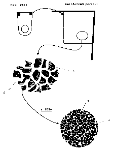
[0017] Figs. 1 shows a crusher with a vertical axis in
which the impactors of the present invention are used.
[0018] Fig. 2 shows a crusher with a vertical axis in
which the impactors of the present invention are also used.
[0019] Fig. 3 shows an impactor/hammer of the prior art
without any reinforcement.
[0020] Figs. 4a-4b show a hammer with two possible
reinforcement types. This reinforcement geometry if of course
not restrictive
[0021] Figs. 5a-5h schematically illustrate the method
for manufacturing a hammer according to the invention.
- step 5a shows the device for mixing the titanium and carbon
powders;
- step 5b shows the compaction of the powders between two rolls
followed by crushing and sifting with recycling of the too
fine particles;
- Fig. Sc shows a sand mold in which a barrier is placed for
containing the granules of powder compacted at the location
of the reinforcement of the impactor (hammer);
CA 02735877 2011-03-02
6
- Fig. 5d shows an enlargement of the reinforcement area in
which the compacted granules comprising the reagents
precursor of TiC are located;
- step 5e shows the casting of the ferrous alloy into the mold;
- Fig. 5f schematically shows the hammer which is the result of
the casting;
- Fig. 5g shows an enlargement of the areas with a high
concentration of TiC nodules;
- Fig. 5h shows an enlargement within a same area with a high
concentration of TiC nodules. The micrometric nodules are
individually surrounded by the cast metal.
[0022]
Fig. 6 illustrates a binocular view of a
polished, non-etched surface of a section of the reinforced
portion of an impactor according to the invention with
millimetric areas (in pale grey) concentrated with micrometric
globular titanium carbide (TiC nodules). The dark portion
illustrates the metal matrix (steel or cast iron) filling both
the space between these areas concentrated with micrometric
globular titanium carbide but also the spaces between the
globules themselves.
[0023]
Figs. 7 and 8 illustrate views taken with an SEM
electron microscope of micrometric globular titanium carbide
on polished and non-etched surfaces at different
magnifications. It is seen that in this particular case, most
of the titanium carbide globules have a size smaller than 10
pm.
[0024]
Fig. 9 illustrates a view of micrometric globular
titanium carbide on a fracture surface taken with an SEM
electron microscope. It is seen that the titanium carbide
globules are perfectly incorporated into the metal matrix.
This proves that the cast metal infiltrates (impregnates)
completely the pores during the casting once the chemical
reaction between titanium and carbon is initiated.
CA 02735877 2011-03-02
7
[0025] Fig. 10 schematically illustrate the
reinforcement areas on an impactor of the hammer type. The
reinforced corners are analogous to those of Fig. 4b and the
schematic enlargement of the reinforcement areas allows to
show the reinforcement macro-microstructure according to the
invention.
Caption
1. millimetric areas concentrated with micrometric globular
particles of titanium carbide (nodules)
2. millimetric interstices filled with the cast alloy globally
free of micrometric globular particles of titanium carbide
3. micrometric interstices between the TiC nodules also
infiltrated by the cast alloy
4. micrometric globular titanium carbide, in areas
concentrated with titanium carbide
5. titanium carbide reinforcement
6. gas defects
7. hammer/impactor
8. mixer of Ti and C powders
9. hopper
10. roll
11. grinding mill
12. outlet grid
13. sieve
14. recycling of the too fine particles towards the hopper
15. sand mold
16. barrier containing the compacted granules of Ti/C mixture
17. cast ladle
18. impactor (diagram)
Detailed description of the invention
[0026] In materials science, a SHS reaction or
Self-propagating High temperature Synthesis is a self-
CA 02735877 2011-03-02
8
propagating high temperature synthesis where reaction
temperatures generally above 1,500 C, or even 2,000 C are
reached. For example, the reaction between titanium powder and
carbon powder in order to obtain titanium carbide TiC is
strongly exothermic. Only a little energy is needed for
locally initiating the reaction. Then, the reaction will
spontaneously propagate to the totality of the mixture of the
reagents by means of the high temperatures reached. After
initiation of the reaction, a reaction front develops which
thus propagates spontaneously (self-propagating) and which
allows titanium carbide to be obtained from titanium and
carbon. The thereby obtained titanium carbide is said to be o
obtained in situ because it does not stem from the cast
ferrous alloy.
[0027] The mixtures of reagent powders comprise carbon
powder and titanium powder and are compressed into plates and
then crushed in order to obtain granules, the size of which
varies from 1 to 12 mm, preferably from 1 to 6 mm, and more
preferably from 1.4 to 4 mm. These granules are not 100%
compacted. They are generally compressed to between 55 and 95%
of the theoretical density. These granules allow an easy
use/handling (see Figs. 3a-3h).
[0028] These millimetric granules of mixed carbon and
titanium powders obtained according to the diagrams of
Figs. 3a-3h are the precursors of the titanium carbide to be
generated and allow portions of molds with various or
irregular shapes to be easily filled. These granules may be
maintained in place in the mold 15 by means of a barrier 16,
for example. The shaping or the assembling of these granules
may also be achieved with an adhesive.
[0029] The composite impactor according to the present
invention has a reinforcement macro-microstructure which may
further be called an alternating structure of areas
concentrated with globular micrometric particles of titanium
CA 02735877 2013-06-28
54509-1
9
carbide separated by areas which are practically free of them. Such a
structure is obtained by the reaction in the mold 15 of the granules
comprising a mixture of carbon and titanium powders. This reaction
is initiated by the casting heat of the cast iron or the steel used
for casting the whole part and therefore both the non-reinforced
portion and the reinforced portion (see Fig. 3e). Casting therefore
triggers an exothermic self-propagating high temperature synthesis of
the mixture of carbon and titanium powders compacted as granules
(self-propagating high temperature synthesis - SHS) and placed
beforehand in the mold 15. The reaction then has the particularity
of continuing to propagate as soon as it is initiated.
[0030] This high temperature synthesis (SHS) allows an easy
infiltration of all the millimetric and micrometric interstices
=
by the cast iron or cast steel (Figs. 5g and 5h). By increasing
the wettability, the infiltration may be achieved over any
reinforcement thickness or depth of the impactor. After SHS
reaction and an infiltration by an outer cast metal, it
advantageously allows to generate one or more reinforcing areas
on the impactor comprising a high concentration of micrometric
globular particles of titanium carbide (which may further be called
clusters of nodules), said areas having a size of the order of one
millimeter or of a few millimeters, and which alternate with areas
substantially free of globular titanium carbide.
[0031] Once these granules have reacted according to a SHS
reaction, the reinforcement areas where these granules were
=
located show a concentrated dispersion of micrometric globular
particles 4 of TiC (globules), the micrometric interstices 3 of
which have also been infiltrated by the cast metal which here is
cast iron or steel. It is important to note that the millimetric
and micrometric interstices are infiltrated by the same metal
matrix as the
CA 02735877 2011-03-02
one which forms the non-reinforced portion of the impactor;
this allows total freedom in the selection of the cast metal.
In the finally obtained impactor, the reinforcement areas with
a high concentration of titanium carbide consist of
5 micrometric globular TiC particles in a significant percentage
(between about 35 and about 70% by volume) and of the
infiltration ferrous alloy.
[0032] By micrometric globular particles it is meant
globally spheroidal particles which have a size ranging from 1
10 pm to a few tens of pm at the very most, the large majority of
these particles having a size of less than 50 pm, and even
less than 20 pm, or even 10 pm. We also call them TiC
globules. This globular shape is characteristic of a method
for obtaining titanium carbide by self-propagating synthesis
SHS (see Fig. 8).
Obtaining granules (Ti + C version) for reinforcing the
impactor
[0033] The method for obtaining the granules is
illustrated in Fig. 5a-5h. The granules of carbon/titanium
reagents are obtained by compaction between rolls 10 in order
to obtain strips which are then crushed in a crusher 11. The
mixing of the powders is carried out in a mixer 8 consisting
of a tank provided with blades, in order to favor homogeneity.
The mixture then passes into a granulation apparatus through a
hopper 9. This machine comprises two rolls 10, through which
the material is passed. Pressure is applied on these rolls 10,
which allows the compression of the material. At the outlet a
strip of compressed material is obtained which is then crushed
in order to obtain the granules. These granules are then
sifted to the desired grain size in a sieve 13. A significant
parameter is the pressure applied on the rolls. The higher
this pressure, the more the strip, and therefore the granules,
will be compressed. The density of the strips, and therefore
CA 02735877 2011-03-02
11
of the granules, may thus be varied between 55 and 95% of the
theoretical density which is 3.75 g/cm3 for the stoichiometric
mixture of titanium and carbon. The apparent density (taking
into account porosity) is then located between 2.06 and 3.56
g/cm3.
[0034] The compaction level of the strips depends on the
applied pressure (in Pa) on the rolls (diameter 200 mm, width
30 mm). For a low compaction level, of the order of 106 Pa, a
density on the strips of the order of 55% of the theoretical
density is obtained. After passing through the rolls 10 in
order to compress this material, the apparent density of the
granules is 3.75 x 0.55, i.e. 2.06 g/cm3.
[0035] For a high compaction level, of the order of
25.106 Pa, a density on the strips of 90% of the theoretical
density is obtained, i.e. an apparent density of 3.38 g/cm3. In
practice, it is possible to attain up to 95% of the
theoretical density.
[0036] Therefore, the granules obtained from the raw
material Ti + C are porous. This porosity varies from 5% for
very highly compressed granules to 45% for slightly compressed
granules.
[0037] In addition to the compaction level, it is also
possible to adjust the grain size distribution of the granules
as well as their shape during the operation of crushing the
strips and sifting the Ti + C granules. The non-desired grain
size fractions are recycled at will (see Fig. 3b). The
obtained granules globally have a size between 1 and 12 mm,
preferably between 1 and 6 mm, and more preferably between 1.4
and 4 mm.
Making of the reinforcement area in the composite impactor
according to the invention
[0038] The granules are made as described above. In
order to obtain a three-dimensional structure or a
CA 02735877 2011-03-02
12
superstructure/macro-microstructure with these granules, they
are positioned in the areas of the mold where it is desired to
reinforce the part. This is achieved by agglomerating the
granules either by means of an adhesive, or by confining them
in a container or by any other means (barrier 16).
The bulk density of the stack of the Ti + C granules is
measured according to the ISO 697 standard and depends on the
compaction level of the strips, on the grain size distribution
of the granules and on the method for crushing the strips,
which influences the shape of the granules.
The bulk density of these Ti + C granules is generally of the
order of 0.9 g/cm3 to 2.5 g/cm3 depending on the compaction
level of these granules and on the density of the stack.
[0039] Before reaction, there is therefore a stack of
porous granules consisting of a mixture of titanium powder and
carbon powder.
[0040] During the reaction Ti + C
TiC, a volume
contraction of the order of 24% occurs, upon passing from the
reagents to the product (a contraction originating from the
density difference between the reagents and the products).
Thus, the theoretical density of the Ti + C mixture is 3.75
g/cm3 and the theoretical density of TiC is 4.93 g/cm3. In the
final product, after the reaction for obtaining TiC, the cast
metal will infiltrate:
- the microscopic porosity present in the spaces with a high
titanium carbide concentration, depending on the initial
compaction level of these granules;
- the millimetric spaces between the areas with a high titanium
carbide concentration, depending on the initial stack of the
granules (bulk density);
- the porosity originating from the volume contraction during
the reaction between Ti + C for obtaining TiC.
CA 02735877 2011-03-02
13
Examples
[0041] In the examples which follow, the following raw
materials were used:
- titanium H.C. STARCK, Amperit 155.066, less than 200 mesh,
- graphite carbon GK Kropfmuhl, UF4, > 99.5 %, less than 15 um,
- Fe, in the form of HSS M2 Steel, less than 25 um,
- proportions:
- Ti + C 100 g Ti - 24.5 g C
- Ti + C + Fe 100 g Ti - 24.5 g C - 35.2 g Fe
Mixing for 15 min. in a Lindor mixer, under argon.
The granulation was carried out with a Sahut-Conreur
granulator.
For the Ti+C+Fe and Ti+C mixtures, the compactness of the
granules was obtained by varying the pressure between the
rolls from 10 to 250.105 Pa.
The reinforcement was carried out by placing granules in a
metal container, which is then judiciously placed in the mold
at the location where the impactor is likely to be reinforced.
Then, the steel or the cast iron is cast into the mold.
Example 1
[0042] In this example, the aim is to make an impactor,
the reinforced areas of which comprise a global volume
percentage of TiC of about 42%. For this purpose, a strip is
made by compaction to 85% of the theoretical density of a
mixture of C and of Ti. After crushing, the granules are
sifted so as to obtain a dimension of granules located between
1.4 and 4 mm. A bulk density of the order of 2.1 g/cm3 is
obtained (35% of space between the granules + 15% of porosity
in the granules).
[0043] The granules are positioned in the mold at the
location of the portion to be reinforced which thus comprises
65% by volume of porous granules. A cast iron with chromium
(3% C, 25% Cr) is then cast at about 1500 C in a non-preheated
CA 02735877 2011-03-02
14
sand mold. The reaction between the Ti and the C is initiated
by the heat of the cast iron. This casting is carried out
without any protective atmosphere. After reaction, in the
reinforced portion, 65% by volume of areas with a high
concentration of about 65% of globular titanium carbide are
obtained, i.e. 42% by the global volume of TIC in the
reinforced portion of the impactor.
Example 2
[0044] In this example, the aim is to make an impactor,
the reinforced areas of which comprise a global volume
percentage of TiC of about 30%. For this purpose, a strip is
made by compaction to 70% of the theoretical density of a
mixture of C and of Ti. After crushing, the granules are
sifted so as to obtain a dimension of granules located between
1.4 and 4 mm. A bulk density of the order of 1.4 g/cm3 is
obtained (45% of space between the granules + 30% of porosity
in the granules). The granules are positioned in the portion
to be reinforced which thus comprises 55% by volume of porous
granules. After reaction, in the reinforced portion, 55% by
volume of areas with a high concentration of about 53% of
globular titanium carbide are obtained, i.e. about 30% by the
global volume of TiC in the reinforced portion of the
impactor.
Example 3
[0045] In this example, the aim is to make an impactor,
the reinforced areas of which comprise a global volume
percentage of TiC of about 20%. For this purpose, a strip is
made by compaction to 60% of the theoretical density of a
mixture of C and of Ti. After crushing, the granules are
sifted so as to obtain a dimension of granules located between
1 and 6 mm. A bulk density of the order of 1.0 g/cm3 is
obtained (55% of space between the granules + 40% of porosity
CA 02735877 2011-03-02
in the granules). The granules are positioned in the portion
to be reinforced which thus comprises 45% by volume of porous
granules. After reaction, in the reinforced portion, 45% by
volume of areas concentrated to about 45% of globular titanium
5 carbide are obtained, i.e. 20% of the global volume of TiC in
the reinforced portion of the impactor.
Example 4
[0046] In this example, it was sought to attenuate the
10 intensity of the reaction between the carbon and the titanium
by adding a ferrous alloy as a powder therein. Like in Example
2, the aim is to make an impactor, the reinforced areas of
which comprise a global volume percentage of TiC of about 30%.
For this purpose, a strip is made by compaction to 85% of the
15 theoretical density of a mixture of 15% C, 63% Ti and 22% Fe
by weight. After crushing, the granules are sifted so as to
attain a dimension of granules located between 1.4 and 4 mm. A
bulk density of the order of 2 g/cm' is obtained (45% of space
between the granules + 15% of porosity in the granules). The
granules are positioned in the portion to be reinforced which
thus comprises 55% by volume of porous granules. After
reaction, in the reinforced portion, 55% by volume of areas
with a high concentration of about 55% of globular titanium
carbide are obtained, i.e. 30% by volume of the global
titanium carbide in the reinforced macro-microstructure of the
impactor.
[0047] The following tables show the numerous possible
combinations.
Table 1 (Ti + 0.98 C)
[0048] Global percentage of TiC obtained in the
reinforced macro-microstructure after reaction of Ti + 0.98 C
in the reinforced portion of the impactor.
CA 02735877 2011-03-02
16
Compaction of the granules
( /0 of the theoretical density which is 55 60 65 70 75 80
85 90 95
3,75 g/cm3)
Filling of the reinforced portion 70 29.3 31.9 34.6 37.2 39.9 42.6 45.2 47.9
50.5
of the part (% by volume) 65 27.2 29.6 32.1 34.6 37.1 39.5 42.0 44.5 46.9
55 210 25.1 27.2 29.3 31.4 314 35.5 37.6 391
45 18.8 20.5 22.2 219 25.7 27.4 29.1 30.8 32.5
This table shows that with a compaction level ranging from 55
to 95% for the strips and therefore the granules, it is
possible to perform granule filling levels in the reinforced
portion of the impactor ranging from 45% to 70% by volume
(ratio between the total volume of the granules and the volume
of their confinement). Thus, in order to obtain a global TiC
concentration in the reinforced portion of about 29% by volume
(in bold characters in the table), it is possible to proceed
with different combinations such as for example 60% compaction
and 65% filling, or 70% compaction and 55% filling, or further
85% compaction and 45% filling. In order to obtain granule
filling levels in the reinforced portion ranging up to 70% by
volume, it is mandatory to apply a vibration in order to pack
the granules. In this case, the ISO 697 standard for measuring
the filling level is no longer applicable and the amount of
material in a given volume is measured.
Table 2
[0049] Relationship between the compaction level, the
theoretical density and the TiC percentage obtained after
reaction in the granule.
Compaction of the 55 60 65 70 75 80 85 90 95
granules
Density in g/cm3 2.06 2.25 2.44 2.63 2.81 3.00 3.19 3.38 3.56
TiC obtained after 41.8 45.6 49.4 53.2 57.0 60.8 64.6 68.4 72.2
reaction (and contraction)
in volume % in the
granules
CA 02735877 2011-03-02
17
Here, we have represented the density of the granules
according to their compaction level and the volume percent of
TiC obtained after reaction and therefore contraction of about
24% by volume was inferred therefrom. Granules compacted to
95% of their theoretical density therefore allow to obtain
after reaction a concentration of 72.2% by volume of TiC.
Table 3
[0050] Bulk density of the stack of granules
Compaction 55
60 65 70 75 80 85 90 95
Filling of the reinforced portion of 70 1.4 1.6 1.7 1.8 2 2.1
2.2 2.4 2.5
the part in volume % 65
1.3* 1.5 1.6 1.7 1.8 2.0 2.1 2.2 2.3
55 1.1 1.2 1.3 1.4 1.5 1.7 1.8 1.9 2.0
45 0.9 tO 1.1 1.2 1.3 1.4 1.4 1.5 1.6
(*) Bulk density (1.3) - theoretical density (3.75 g/cm3) x
0.65 (filling) x 0.55 (compaction)
In practice, these tables are used as abacuses by the user of
this technology, who sets a global TiC percentage to be
obtained in the reinforced portion of the impactor and who,
depending on this, determines the filling level and the
compaction of the granules which he/she will use. The same
tables were produced for a mixture of Ti + C + Fe powders.
Ti + 0.98 C + Fe
[0051]
Here, the inventor aimed at a mixture allowing to
obtain 15% by volume of iron after reaction. The mixture
proportion which was used is:
100g Ti + 24.5g C + 35.2g Fe
By iron powder it is meant: pure iron or an iron alloy.
Theoretical density of the mixture: 4.25g/cm3
Volume shrinkage during the reaction: 21%
CA 02735877 2011-03-02
18
Table 4
[0052]
Global TiC percentage obtained in the reinforced
macro-microstructure after reaction of Ti + 0.98 C + Fe in the
reinforced portion of the impactor.
Compaction of the granules (% of
the theoretical density which is 4.25 55 60 65 70 75 80
85 90 95
g/cm3)
Filling of the reinforced 70 25.9 28.2 30.6 32.9 35.5 37.6 40.0 42.3 44.7
portion of the part (vol.%) 65 24.0 26.2 28.4 30.6 32.7 34.9 37.1 39.3
41.5
55 20.3 22.2 24.0 25.9 27.7 29.5 31.4 33.2 35.1
45 16.6 18.1 19.6 21.2 22.7 24.2 25.7 27.2 28.7
Again, in order to obtain a global TiC concentration in the
reinforced portion of about 26% by volume (in bold characters
in the table), it is possible to proceed with different
combinations such as for example 55% compaction and 70%
filling, or 60% compaction and 65% filling, or 70% compaction
and 55% filling, or further 85% compaction and 45% filling.
Table 5
[0053]
Relationship between the compaction level, the
theoretical density and the TiC percentage, obtained after
reaction in the granule while taking into account the presence
of iron.
Compaction of the granules 55 60 65 70 75 80 85 90
95
Density in g/cm3
2.34 2.55 2.76 2.98 3.19 3.40 3.61 3.83 4.04
TiC obtained after reaction (and 36.9 40.3 43.6 47.0 50.4 53.7 57.1 60.4 63.8
contraction) in vol.% in the granules
Table 6
[0054]
Bulk density of the stack of (Ti + C + Fe)
granules
Compaction
55 60 65 70 75 80 85 90 95
Filling of the reinforced portion of 70 1.6
1.8 1.9 2.1 2.2 2.4 2.5 2.7 2.8
the part in vol.%
65 1.5* 1.7 1.8 1.9 2.1 2.2 2.3 2.5 2.6
55 1.3 1.4 1.5 1.6 1.8 1.9 2.0 2.1 2.2
45 1.1 1.1 1.2 1.3 1.4 1.5 1.6 1.7 1.8
CA 02735877 2011-03-02
19
(*) Bulk density (1.5) = theoretical density (4.25) x 0.65
(filling) x 0.55 (compaction)
Advantages
[0055] The present invention has the following
advantages in comparison with the state of the art in general:
Better resistance to impacts
[0056] With the present method, porous millimetric
granules are obtained which are embedded into the infiltration
metal alloy. These millimetric granules themselves consist of
microscopic particles of TiC with a globular tendency also
embedded into the infiltration metal alloy. This system allows
to obtain an impactor with a reinforcement area comprising a
macrostructure within which there is an identical
microstructure at a scale which is about a thousand times
smaller.
[0057] The fact that the reinforcement area of the
impactor comprises small hard globular particles of titanium
carbide finely dispersed in a metal matrix surrounding them
allows to avoid the formation and propagation of cracks (see
Figs. 4 and 6). One has thus a double dissipative system for
cracks.
[0058] The cracks generally originate at the most
brittle locations, which in this case are the TiC particle or
the interface between this particle and the infiltration metal
alloy. If a crack originates at the interface or in the
micrometric TiC particle, the propagation of this crack is
then hindered by the infiltration alloy which surrounds this
particle. The toughness of the infiltration alloy is greater
than that of the ceramic TiC particle. The crack needs more
energy for passing from one particle to another, for crossing
the micrometric spaces which exist between the particles.
CA 02735877 2011-03-02
Maximum flexibility for the application parameters
[0059] In addition to the compaction level of the
granules, two parameters may be varied, which are the grain
size fraction and the shape of the granules, and therefore
5 their bulk density. On the other hand, in a reinforcement
technique with inserts, only the compaction level of the
latter can be varied within a limited range. As regards the
desired shape to be given to the reinforcement, taking into
account the design of the impactor and the location where
10 reinforcement is desired, the use of granules allows further
possibilities and adaptation.
Advantages as regards manufacturing
[0060] The use of a stack of porous granules as a
15 reinforcement has certain advantages as regards manufacturing:
- less gas emission,
- less sensitivity to crack,
- better localization of the reinforcement in the impactor.
The reaction between Ti and C is strongly exothermic. The rise
20 in temperature causes degassing of the reagents, i.e. volatile
materials comprised in the reagents (H20 in carbon, H2, N2 in
titanium). The higher the reaction temperature, the more
significant is this emission. The granule technique allows to
limit the temperature, to limit the gas volume and to more
easily discharge the gases and thus limit the gas defects.
(see Fig. 9 with an undesirable gas bubble).
Low sensitivity to crack during the manufacturing of the
impactor according to the invention
[0061] The expansion coefficient of the TiC
reinforcement is lower than that of the ferrous alloy matrix
(expansion coefficient of TiC: 7.5 10-6/K and of the ferrous
alloy: about 12.0 10-6/K). This difference in expansion
coefficients has the consequence of generating stresses in the
CA 02735877 2011-03-02
21
material during the solidification phase and also during the
heat treatment. If these stresses are too significant, cracks
may appear in the part and lead to its reject. In the present
invention a small proportion of TiC reinforcement is used
(less than 50% by volume), which causes less stresses in the
part. Further, the presence of a more ductile matrix between
the micrometric globular TiC particles in the alternating
areas of low and high concentration allows to better handle
possible local stresses.
Excellent maintenance of the reinforcement in the impactor
[0062] In the present
invention, the frontier between
the reinforced portion and the non-reinforced portion of the
impactor is not abrupt since there is a continuity of the
metal matrix between the reinforced portion and the non-
reinforced portion, which allows to protect it against a
complete detachment of the reinforcement.
Test results
[0063] Three tests were
carried out with impactors of
the hammer type of the type of the one illustrated in Fig. 4b
and Fig. 10 over a range of weights from 30 to 130 kg.
Test 1
weight of the hammers: 30 to 70 kg
crushed material: cement works clinker
increase of the lifetime of the hammer in comparison with a
hammer made of quenched steel: 200%
Test 2
weight of the hammers: 70 to 130 kg
crushed material: limestone rock
stage: primary
CA 02735877 2011-03-02
22
increase of the lifetime of the hammer in comparison with a
hammer made of quenched steel: 100 to 200 %
Test 3
weight of the hammers: 30 to 80 kg
crushed material: limestone rock
stage: secondary
increase of the lifetime of the part: 100 to 200 %