Note: Descriptions are shown in the official language in which they were submitted.
CA 02736757 2011-03-09
WO 2010/039486 PCT/US2009/057807
LIGHTING APPARATUS WITH HEAT DISSIPATION SYSTEM
FIELD OF THE DISCLOSURE
[0001] The present disclosure relates generally to a lighting apparatus. More
specifically, the
disclosure relates to various structures facilitating heat dissipation in a
lighting apparatus.
BACKGROUND OF THE DISCLOSURE
[0002] When designing and implementing lighting apparatuses, generation of
heat is one of
many factors to be contemplated. In lighting apparatuses, light sources can
create heat which may
not be desirable to the functionality of the apparatus. Excess heat may result
in melting of
components, malfunctioning of proximate devices, or otherwise undesirable
results. Also, excessive
heat may diminish the efficiency or the lifespan of components within a
lighting apparatus.
Correspondingly, cooler operating temperatures may increase effectiveness of
components within a
lighting apparatus.
[0003] Heat can be transferred in three ways: convection, conduction, and
radiation. These
three methods of heat transfer can be harnessed to transfer heat away from a
lighting apparatus, if
the existence of such heat is undesirable.
SUMMARY OF THE DISCLOSURE
[0004] In one aspect, the disclosure presents a lighting apparatus that can
include a light source,
a plate, and a frame. The light source can include one or more lighting
elements. The plate can be
in thermal communication with the light source and have a dissipative portion
that extends outward
from the point of thermal communication between the plate and the light
source. The frame can at
least partially enclose the light source. The frame can also be in thermal
communication with one of
the plate or the light source and have a footprint that fits substantially
within the plate.
[0005] In various embodiments, a lighting element can be a light emitting
diode mounted on a
printed circuit board. The lighting apparatus can also include a housing in
communication with a
portion of the plate. The housing can create a volume that houses the plate
and the light source.
[0006] In one embodiment, the plate and frame are constructed of sheet metal.
The plate can
be in direct contact with a surface of the light source. In another
embodiment, the lighting apparatus
includes a lens that covers at least a portion of the light source.
[0007] In another aspect, the disclosure presents a lighting apparatus having
a light source, a
plate and a frame. The light source can include one or more lighting elements.
The plate can have a
dissipative portion defining an outermost perimeter of the plate. The frame
can at least partially
enclose the light source. The frame can be in thermal communication with at
least one of the plate
or the light source. The frame can also have an outer perimeter substantially
within the outermost
perimeter of the plate. The dissipative portion extends away from the point of
thermal
communication with the frame.
-1-
CA 02736757 2011-03-09
WO 2010/039486 PCT/US2009/057807
[0008] In another aspect, the lighting apparatus includes a light source, a
plate, and frame. The
light source can include one or more lighting elements. The plate can have a
dissipative portion
extending outward from a point of thermal communication between the plate and
the light source.
The frame can at least partially enclose the light source and may also be in
thermal communication
therewith.
BRIEF DESCRIPTION OF THE DRAWINGS
[0009] Figure 1 shows a perspective view of an embodiment of a lighting
apparatus.
[0010] Figure 2 shows a side view of the lighting apparatus of Figure 1.
[0011] Figure 3 shows a cross-sectional view of the lighting apparatus of
Figure 1.
[0012] Figure 3A shows an enlarged, detailed view of a portion of Figure 3.
[0013] Figure 4 shows a perspective view of another embodiment of a lighting
apparatus.
[0014] Figure 5 shows a cross-sectional view of the lighting apparatus of
Figure 4.
[0015] Figure 5A shows an enlarged, detailed view of a portion of Figure 5.
[0016] Figure 6 shows a bottom view of another embodiment of a lighting
apparatus.
[0017] Figure 7 shows a cross-sectional view of the lighting apparatus of
Figure 6.
[0018] Figure 7A shows an enlarged, detailed view of a portion of Figure 7.
DETAILED DESCRIPTION OF THE DISCLOSURE
[0019] The present disclosure describes a heat dissipation system for use in
lighting
apparatuses. Aspects and embodiments of the present disclosure provide
lighting apparatuses and
heat dissipation systems for those apparatuses. By placing lighting elements
and other heat
producing sources in thermal communication with heat conductive materials,
heat can be transferred
away from lighting elements and surrounding structure to other areas of the
light apparatus,
including the heat dissipation system which facilitates a high rate of heat
dissipation. Further, the
surface area, location, and orientation of the heat dissipating materials,
quickly and efficiently
dissipate heat. Strategic location of the heat dissipation system components
facilitates efficient
radiation as well as convection.
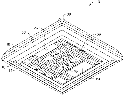
[0020] Referring now to Figures 1-3A, an embodiment of a lighting apparatus 10
is shown and
described. The lighting apparatus 10 includes a frame 14, a plate 18, a
housing 22, a light source 26,
a fixing mechanism 30, and a lens 34. The light source 26 includes a plurality
of lighting elements
38. The light source 26 is in thermal communication, as defined below, with
the plate 18. The
frame 14, which, as shown, partially encloses the light source, is in thermal
communication with the
plate 18 and the lens 34. The housing 22 is in thermal communication with the
plate 18. The fixing
mechanism 30 is attached to the housing 22 and facilitates mounting of the
lighting apparatus in a
desired location.
[0021] In one embodiment, the frame 14 is roughly square in shape and
partially encloses the
light source 14 on four sides. The frame 14 in conjunction with the plate 18
and the lens 34 encloses
the light source 26 on all sides, with necessary access for wiring, attachment
mechanisms, and the
-2-
CA 02736757 2012-09-07
Attorney Docket: 074280-0165
like. The frame 14, in various embodiments, can also have a different shape.
One example of a
frame with a different shape is shown with reference to Figure 4. Depending on
the application,
other examples of the shape of the frame 14 include, but are not limited to,
rectangular, circular, or
other shape that permits partial enclosure of the light source 26. The frame
14 is in thermal
communication with at least one of the plate 18, the light source 26, or both.
The frame 14 is also in
thermal communication with the lens 34. In various embodiments, the heat
dissipation system of the
present disclosure can be, but is not necessarily, practiced without a lens
34. The frame 14 shown in
Figure 3A is wider at its thermal communication with the plate 18, which
defines an outer perimeter,
than it is at the thermal communication with the lens 34, which defines a lens
perimeter. This
change in width creates an inwardly sloped portion 16 of the frame 14. In
other embodiments, the
frame 14 can have an outwardly sloped portion, a perpendicular extension from
the plate 18 with no
slope, or other protrusion.
100221 In one embodiment, the light source 26 comprises at least one lighting
element 38.
Possible lighting elements 38 include incandescent light bulbs, fluorescent
lights, light emitting
diodes (LEDs), organic LEDs (OLEDs), and other commercially or non-
commercially available
light emanating components.
[00231 In one embodiment, LEDs are fabricated or mounted onto a printed
circuit board (PCB).
The LEDs can be of any kind, color (i.e. emitting any color or white light or
mixture of colors and
white light as the intended lighting arrangement requires) and luminance
capacity or intensity,
preferably in the visible spectrum. One or more PCBs are in thermal
communication with the plate
18. The lighting elements 38 on the PCB emanate light that radiates through
the lens 34. In one
embodiment, the lighting apparatus can be used with Nichia (trade-mark) NSW6-
083x and/or Osram
(trade-mark) LUW W5AM xxxx xxxx LEDs.
100241 In an alternative embodiment, the present disclosure relates to a
lighting apparatus
having a light source 26, a plurality of light elements 38, and a plurality of
reflectors 39, as
described in co-pending US provisional patent application 60/980,562, filed
October 17, 2007 which
is publicly available on the United States Patent Office website public PAIR
database at
www.uspto.gov/patent/index.jsp.
[00251 The plate 18 can be roughly square in shape and can be substantially
flat in the area in
thermal communication with the housing 22. The plate 18, in various
embodiments, can be in
thermal communication with the one of the frame 14 or light source 26. The
thermal
communication between the plate 18 and the frame 14 can, in another
embodiment, occur via the
light source 26. The plate 18 can also have a different shape. For example,
depending on the
application, the shape of the plate 18 can be, but is not limited to being,
rectangular, circular, or
other shape. Furthermore, the plate 18 can also have vertical shape, instead
of being substantially
flat. For example, the plate 18 can be, but is not limited to being, curved, s-
shaped, or otherwise
bent. The plate 18 has an outermost perimeter, which is the perimeter of the
plate 18 in a plane
parallel to the light source 26, lens 34, or frame 14 and at its outermost
position. As shown, the
DOCSTOR: 2435301\5
-3-
CA 02736757 2011-03-09
WO 2010/039486 PCT/US2009/057807
outermost perimeter of the plate is the widest perimeter of the point of
thermal communication
between the plate 18 and the housing 22. In an alternate embodiment, the plate
18 has a base 43 that
is substantially the same size as its point of contact with the housing 22,
and, at the outer perimeter
of the frame, a dissipative portion of the plate 18 protrudes away from the
housing 22 and extends to
be substantially parallel to the inwardly sloped portion 16 of the frame 14.
As is described below,
this parallel protrusion permits for an angling of the heat dissipation
surface towards cooler areas.
Alternatively, the plate base 43 and the protruding dissipative portion 46 of
the plate 18 can be two
separate pieces in thermal communication. The frame 14 has an outer footprint
perimeter located at
the thermal communication between the frame 14 and the plate 18. The outer
footprint perimeter is
substantially within the outermost perimeter defined by the plate 18.
Alternatively, the frame 14
outer footprint perimeter, in various embodiments, can be, but is not limited
to being, partially
outside the outermost perimeter of the plate 18.
[0026] In the embodiment shown in Figures 1-3A, the housing 22 is in thermal
communication
with the plate 18 and the fixing mechanism 30. At the point of thermal
communication with the
plate 18, the housing 22 is roughly in the shape of a square. The housing 22,
in various alternative
embodiments, can take different shapes at the point of thermal communication
with the plate 18.
For example, the shape can be, but is not limited to, rectangular, circular,
or other shape.
[0027] The fixing mechanism 30 facilitates mounting and positioning the light
source 26. The
fixing mechanism 30 is configured to house necessary electrical wiring for
operation of the lighting
apparatus 10, such as power wires. The fixing mechanism, for example, can
transport wiring to the
housing 22 so as to cover and/or contain components such as a power supply,
regulator, driver
circuits or other desired components/circuits to operate the light apparatus.
In one embodiment, the
fixing mechanism 30 is a pipe.
[0028] The fixing mechanism 30, in various embodiments, can take any shape,
size, or form.
Further, in various embodiments, the fixing mechanism 30 can be constructed
using different
materials, such as, but not limited to, plastic, metal, or rubber. In such
embodiments, the fixing
mechanism may or may not dissipate heat through cooperation with the other
components of the
lighting apparatus 10. Furthermore, the fixing mechanism 30 can be in
releasably affixed to the
housing 22. Alternatively, the fixing mechanism 30 can be merged to be one
single contiguous
piece with the housing 22. The fixing mechanism 30 can have an axis, and that
axis running
perpendicular to the plate 18, as shown in Figures 1-3A, or, alternatively,
parallel to the plate 18, as
shown in Figure 4.
[0029] In various embodiments of the present disclosure, one or more
components of the
lighting apparatus 10 in communication with each other can be releasably
connected. For example,
the plate 18 base in communication with the housing may be a piece separate
from the protrusion of
the plate 46 away from the housing 22. In another example, the frame 14 can be
manufactured to be
one single contiguous piece with the plate 18. Similarly, the plate 18 can be
one single contiguous
-4-
CA 02736757 2011-03-09
WO 2010/039486 PCT/US2009/057807
piece with the housing 22. Various other combinations of separating components
and merging
components are also contemplated.
[0030] As shown, the shape of the housing 22 is roughly a square-bottomed (as
shown in
Figure 1) dome with a flattened top. In various embodiments, the housing can
take many shapes.
For example, the shape of the housing 22 can be, but is not limited to being,
a circular dome, a cone,
a cube, or other shape.
[0031] As shown in Figures 3 and 3A, the thermal communication between the
frame 14 and
the plate 18 occurs via direct contact resulting from mounting the frame 14
and the plate 18 at
contact 40. This direct contact 40 facilitates thermal communication between
the plate 18 and the
housing 22. Thermal communication between the housing 22 and the fixing
mechanism 30 also
occurs via direct contact 41. In various embodiments, the thermal
communication can take other
forms. For example, the thermal communication between any pair of components
can be, but is not
limited to the inclusion of, a rubber gasket, an adhesive, polyurethane, or
other material between the
various components of the lighting apparatus 10. For example, a gasket can be,
but is not limited to,
a SikaTack-Ultrafast polyurethane gasket manufactured by Sika Corporation. The
materials of each
of the components may have the same heat transfer characteristics.
Alternatively, different materials
can be used having varying thermal transfer properties and thus transfer more
or less heat.
[0032] Also, in various embodiments, the surface areas of the various
components can be
increased to effect the thermal transfer properties. For example, the housing
22 can be dimpled.
Also, "fins" (not shown) can be added to one or more of the components. The
fins can be
protrusions extending in various directions from the respective components.
[0033] The thermal transfer during operation of the lighting apparatus 10 is
now discussed.
The light source 26 produces heat. This heat is transferred from the light
source 26 to the plate 18.
This transfer can occur via conduction, convection or radiation depending on
the mode of thermal
communication between the plate 18 and the light source 26. In one embodiment,
this heat is
produced by light elements 38, such as, but not limited to, LEDs and,
correspondingly, the PCB,
driver, power regulator, and components of the light apparatus. In such an
embodiment, the heat
from the LEDs is transferred via a PCB, or other element on which the LEDs are
mounted, to the
plate 18. The heat transmits through the plate 18 to several points. Heat is
carried to the frame
primarily by conduction at direct contact 40. Heat also transmits through the
plate 18 to the
dissipative portion 46 of the plate 18. As shown in Figures 3 and 3A, this
dissipative portion 46 is
substantially parallel to the inward slope 16 of the frame 14. Alternatively,
the dissipative portion
46 can be substantially parallel to a plane defined by the lens 34, as shown
in Figure 7 and 7A. In
one embodiment, the dissipative portion of the plate 46 and the plate 18 can
be separate, non-
contiguous pieces. Heat is also carried through the plate 18 to the housing 22
by conduction at
contact 40. However, in other embodiments, the heat is transferred by
convection or radiation to the
housing. In turn, heat is carried through the housing 22 to the fixing
mechanism 30 at the point of
-5-
CA 02736757 2011-03-09
WO 2010/039486 PCT/US2009/057807
contact 41. In various embodiments, more points of thermal communication can
be added to
increase heat dissipation. For example, an embodiment can have, but is not
limited to having,
another dissipative portion in thermal communication with the plate. Once this
heat has been carried
to other parts of the heat dissipation system of the lighting apparatus 10,
the heat is transferred to the
surrounding environment of the lighting apparatus 10 through convection and/or
radiation.
[0034] The present disclosure contemplates varying the angle of the
dissipative portion 46 to
control direction of heat radiation. As shown in Figures 3 and 3A, the
dissipative portion 46 can be
substantially parallel to an inward slope 16 of the frame 14. In this
configuration, the outside
surface of the dissipative portion 46 radiates heat downward and away from the
light source.
Because hot air rises, and correspondingly cooler air is presumably below the
light when
illuminating downward, placing the outside surface of the dissipative portion
at a downward angle
ensures that it is in contact with cool surroundings and directing radiation
toward cooler locations.
Because greater radiation occurs with greater temperature differential, it is
desirable to place the
outer surface of the dissipative portion 46 in a manner to maximize this
differential. In alternative
embodiments, the dissipative portion 46 can be placed at varying angles so as
to take advantage of
the particular surroundings and to maximize this temperature differential, as
will be contemplated by
one skilled in the art.
[0035] Referring now to Figure 4, another embodiment of a lighting apparatus
10' is shown and
described. In this embodiment, the lighting apparatus 10' includes a frame
14', a plate 18', a
housing 22', a light source 26', a fixing mechanism 30', a lens 34', and a
light element 38'. The
frame 14' and plate 18' have a rectangular form. In various embodiments, the
frame 14' and plate
18' can take any shape, as described above. The fixing mechanism 30' has an
axis that is parallel to
the plate 18'. As described above, the materials and configuration of the
various components can
vary, thus all the possible combination are not repeated.
[0036] Referring now to Figure 5, a cross-sectional view of the lighting
apparatus 10' of Figure
4 is shown and described. The lighting apparatus 10' includes a frame 14', a
plate 18', a light
source 26', a light element 38', a housing 22', a PCB 42', a lens 34', and an
offset gap 50. As
shown, this embodiment differs from the lighting apparatus 10 of Figure 1 by
the inclusion of the
offset gap 50 formed by the frame 14 rather than the plate 18. This offset gap
50 allows for, in
various embodiments, a gasket, an adhesive, a polyurethane, or other material
to cooperate to form
thermal communication between the various components. With this offset gap 50
and point of
contact 40', the shown embodiment permits the use of, but is not limited to, a
gasket or other sealant
to seal against, for example, moisture ingress, while also preserving direct
contact 40' between the
frame 14' and the plate 18'.
[0037] Referring now to Figure 6, another embodiment of a lighting apparatus
10" is shown
and described. The lighting apparatus 10" includes a frame 14", a plate 18", a
light source 26"
including a plurality of light elements 38", and a lens 34". The frame 14" is
in thermal
-6-
CA 02736757 2011-03-09
WO 2010/039486 PCT/US2009/057807
communication with the light source 26" and with the plate 18". The plate 18"
is in thermal
communication with the light source 26" via the frame 14".
[0038] Referring now to Figure 7, a cross-sectional view of the lighting
apparatus 10" of
Figure 6 is shown and described. The frame 14" is in thermal communication
with the plate 18"
and the housing 22". The frame 14" has a point of contact 60 with the plate
18". The thermal
communication is achieved by the gravitational pull of the frame 14" onto the
plate 18", but may be
augmented in other manners such as, by way of example only, screws, latches,
fasteners, adhesives,
springs, clips, or other mechanisms. In this embodiment, the inward slope 16"
of the frame 14"
shares a point of contact with a sloped portion of plate 18". In such a
configuration, heat can be
transferred from the light source 26" to the frame 14" through conduction. The
heat can also be
transferred from the frame 14" to the housing 22" and the plate 18" through
conduction. Using
convection and radiation, heat can be transferred to the environment
surrounding the lighting
apparatus 10" through the frame 14", housing 22", a dissipating portion 46" of
the plate 18", and
through other materials in thermal communication with the light source 26".
Radiation is also
directed downward from the dissipating portion 46" of plate 18".
[00391 Although various embodiments are shown and described above, it should
be understood
other various modifications can also be made. For example, the materials used
to construct the
thermal conductive elements of the lighting apparatus can be constructed of
sheet metal. In other
embodiments, other materials such as gold, silver, aluminum, stainless steel,
or other materials can
be used. For example, ASTM: Aluminum 3003 H14 can be used. Of course, various
combinations
of one or more materials can also be used. Also, although most of the
components are shown as
being relatively smooth, it should be understood that they can be textured,
contoured, undulated,
painted, or otherwise non-flat or otherwise modified to increase or decrease
their thermal transfer
properties. Also, in various embodiments of the present disclosure, the plate
18,18',18" or the
dissipative portion of the plate 46,46',46" is at least partially observable
by an ordinary observer of
the light in its normal operation. In one embodiment, an observer whose view
is perpendicular to
the plane created by the lens 34, frame 14, or plate 18 can observe, in plain
view, at least a portion
of the plate 18,18',18" or a dissipative portion of the plate 46,46',46".
[00401 While the disclosure makes reference to the details of preferred
embodiments, it is to be
understood that the disclosure is intended in an illustrative rather than in a
limiting sense, as it is
contemplated that modifications will readily occur to those skilled in the
art, within the spirit of the
disclosure and the scope of the appended claims.
-7-