Note: Descriptions are shown in the official language in which they were submitted.
CA 02737362 2016-04-12
64693-6035
LAMINATED PERFORATED ACOUSTICAL FOAM
BACKGROUND OF THE INVENTION
Field of the Invention
The present invention relates to polymeric foam useful for acoustical
attenuation.
Description of Related Art
There is a desire to increase efficiency in terms of cost and time of
producing thick
foam useful for acoustical attenuation (acoustical foam) production. Time and
cost tends to
increase dramatically as the thickness of the foam increases because
production becomes
more complicated. The primary difficulty with increasing the thickness of an
acoustical
foam is in the step of perforating the foam.
Acoustical foams are often perforated to facilitate blowing agent dissipation
and to
reduce airflow resistivity. Blowing agent dissipation is desirable to exchange
blowing agent
that may be flammable or otherwise undesirable with air. See, for example,
United States
patent (USP) 5,585,058. Acoustical foams also presumably require a
substantially open-cell
structure and a relative low airflow resistivity to be acoustically active
(see, for example,
USP 6720362 at column 1, lines 41-44 and column 10, lines 29-31).
Perforating foam becomes increasingly difficult as foam thickness increases.
Rollers
containing spikes can be suitable for perforating thin foams by rolling the
spikes over the
foam and impressing the spikes into the foam. Such a technique becomes
problematic with
thicker foams if perforations are to achieve appreciable depth. Perforating an
appreciable
distance into thick foams requires relatively long spikes or needles. Rolling
long spikes into
a foam tends to tear the foam as the spikes enter and exit the foam.
Therefore, perforating
thick foams typically requires impaling the foam in a single direction onto a
bed of needles
(or needles into the foam) and then drawing the needles out from the foam in
the same
direction. It is difficult to incorporate such a perforation procedure into a
continuous
process so efficiency decreases in regards to time of manufacturing. Moreover,
the cost of
equipment for impaling foam with a bed of needles tends to be as much as ten
times that of
a roller containing spikes. Therefore, efficiency decreases from a cost
perspective as well.
1
CA 02737362 2011-03-15
WO 2010/036562 PCT/US2009/057398
Blowing agent dissipation also becomes more problematic as foam thickness
increases. Perforation channels, through which blowing agent travels to escape
from cells
internal to a foam, become longer and more tortuous as foam thickness
increases. Gas takes
longer to permeate through a longer more tortuous channel than a shorter less
tortuous
channel. Thicker foams require longer perforation channels to reach internal
cells. As a
result, the longer the perforation channel, the longer it takes for the
blowing agent to find its
way out of the foam. Hence, even when perforated, thicker foams tend to suffer
from
slower blowing agent dissipation than thinner foams that are perforated. The
slower the
dissipation of blowing agent, the longer the foam must be stored before
selling. As a result,
slow blowing agent dissipation is undesirably costly in time and money.
Despite drawbacks to preparing thicker foams, increasing the thickness of foam
is
desirable. Increasing foam thickness tends to increase the acoustical
dampening ability of
the foam, particularly in low frequency ranges.
It is desirable to be able to increase the thickness of acoustical foam
without having
to experience the difficulties in perforating the foam and dissipating the
blowing agent
typically associated with thicker acoustical foams while maintaining or
improving acoustical
activity of the polymeric foam.
BRIEF SUMMARY OF THE INVENTION
The present invention provides a process for preparing acoustical foam of a
given
thickness with the perforation and blowing agent dissipation efficiency of
thinner foam. A
surprising result of the present invention is that perforated acoustical foams
can be
laminated together to form a thicker acoustical foam that achieves similar
acoustical
properties to a non-laminated perforated foam of similar thickness. The result
is surprising
in view of the fact that perforation channels of a first perforated foam are
unlikely to align
perfectly with perforation channels of a second perforated foam that is
laminated to the first
perforated foam. As a result, the airflow resistivity through a laminated foam
should be
noticeably higher than the airflow resistivity through a non-laminated
perforated foam of the
same thickness. Based on prior knowledge, one would then expect the laminated
foam to
have a lower acoustical activity than the non-laminated foam. Acoustical foams
of the
present invention illustrate that this expected result is not the case.
2
CA 02737362 2011-03-15
WO 2010/036562 PCT/US2009/057398
Even more surprising is the fact that the present invention can achieve these
results
from a foam having an open cell content of less than 30%, even a foam having
an open cell
content of less than 10%.
In a first aspect, the present invention is a method for preparing acoustical
foam
comprising the following steps: (a) providing at least two initial polymeric
foams, each
having opposing major surfaces; (b) perforating the initial polymeric foams
through one
major surface all the way the foam and through the opposing major surface to
form
perforated polymeric foams having perforation channels that extend in a
continuous and
linear fashion all the way through the perforated polymeric foam; and (c)
laminating the
perforated polymeric foams together such that a perforated surface of one
perforated
polymeric foam adheres to a perforated surface of another perforated polymeric
foam.
Desirable embodiments of the first aspect include any one or combination of
more
than one of the following characteristics: the perforated polymeric foams have
an average
cell size of at least four millimeters according to ASTM D3576; the polymeric
foams have
an open cell content of less than 30 percent according to ASTM method D6226-
05; the
initial polymeric foams each have a thickness of 30 millimeters or less; step
(b) comprises
compressing the initial polymeric foams into a compressed state and then
perforating the
initial polymeric foams while in a compressed state, especially wherein
perforating occurs
by applying a roller with multiple spikes extending off from the roller into
each initial
polymeric foam such that the spikes penetrate through the initial polymeric
foam as the
initial polymeric foam travels under the roller, and even more preferably
wherein the roller
has a pre-perforated foam side and a perforated foam side and a reed of rods
ejects the
perforated foam from the spikes by comprising rods that extend up to the
roller from the
perforated foam side and reside between the roller and perforated polymeric
foam; step (b)
introduces perforations sufficient to produce a perforated polymeric foam has
a perforation
density of at least 0.8 perforations per square centimeter of perforated major
surface; the
perforation density is two perforations or less per square centimeter of
perforated major
surface; and step (c) comprises heating one or both major surfaces being
adhered together
sufficiently to soften the perforated polymeric foam at the surface or
surfaces and then
contacting the major surfaces of the perforated polymeric foams together,
particularly
wherein step (c) comprises melt welding the perforated polymeric foam major
surfaces
together in an absence of any adhesive between perforated surfaces of the
perforated
3
CA 02737362 2011-03-15
WO 2010/036562 PCT/US2009/057398
polymer foams other than the softened polymer composition of one or more of
the
perforated polymer foams.
In a second aspect, the present invention is an acoustical foam comprising two
or
more perforated polymeric foams having opposing perforated surfaces with at
least one
perforated surface laminated to a perforated surface of another perforated
polymeric foam,
wherein each perforated polymeric foam comprises perforations that extend in a
continuous
linear fashion through the entire perforated polymeric foam, yet fewer than
all of the
perforation channels in any perforated polymeric foam extend in a continuous
linear fashion
without restriction all the way through the acoustical polymeric foam.
Desirable embodiments of the second aspect include any one or combination of
more
than one of the following characteristics: the perforated polymeric foams have
an average
cell size of at least four millimeters according to ASTM D3576; and the
perforated
polymeric foams have a perforation density of at least 0.8 perforations per
square
centimeters of perforated polymeric foam major surface, especially wherein at
least one of
the polymeric foams has a perforation density of two perforations per square
centimeter or
less
The process of the present invention is useful for preparing acoustical
polymeric
foam of the present invention. The acoustical polymeric foam of the present
invention is
useful for use as an acoustical dampening material in applications such as
vehicles,
buildings, and machinery.
BRIEF DESCRIPTION OF THE DRAWINGS
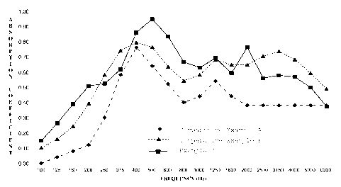
Figure 1 illustrates acoustical performance spectra for Comparative Examples A
and
B and Example 1.
DETAILED DESCRIPTION OF THE INVENTION
ASTM refers to American Society for Testing and Materials. ASTM test methods
either specify the year of the test method using a hyphenated suffix or
correspond to the
most recent test method as of the priority date for this document.
"Acoustically active" in reference to a polymeric foam refers to a foam having
a
noise reduction coefficient (NRC) of 0.3 or greater according to the testing
procedure of
ASTM method C423. "Acoustically active polymeric foam", "acoustical polymeric
foam"
and "acoustical foam" are all synonymous within this document.
4
CA 02737362 2011-03-15
WO 2010/036562 PCT/US2009/057398
"Primary surface" of a polymeric foam is a surface having a planar surface
area
equal to the largest planar surface area of any surface of the polymeric foam.
A planar
surface area is the area of a surface as projected onto a plane and
corresponds to the surface
area of the surface as though the surface was perfectly flat.
"Major surface" of a polymeric foam is a primary surface of the foam as well
as a
surface opposing the primary surface. Both major surfaces may be primary
surfaces, but
only one necessarily is a primary surface.
"Thickness" of a polymeric foam is the distance between major surfaces of the
foam
extending perpendicular to a primary surface of the foam.
"Perforation density" corresponds to the number of perforations in a given
surface
area of a foam surface, typically in a major surface of the foam.
"Perforation channel" corresponds to the passageway formed in a polymeric foam
upon perforating the polymeric foam.
The process of the present invention comprises providing at least two initial
polymeric foams, each having opposing major surfaces. The process includes
perforating
the initial polymeric foams to form perforated polymeric foams. The initial
polymeric
foams and perforated polymeric foams are similar in properties such as
composition,
average cell size, and thickness. The difference between the initial polymeric
foams and
perforated polymeric foams is only the greater extent of perforation in the
perforated
polymeric foam. Therefore, the following foam properties for "polymeric foam"
apply to
both initial polymeric foams and perforated polymeric foams, as well as
acoustical foams of
the present invention, unless otherwise noted.
Polymeric foams comprise a polymer matrix with cells dispersed therein. The
polymer matrix contains a polymer composition that forms a continuous phase in
the
polymer matrix. The polymer composition can be either thermoplastic, thermoset
or a
combination of thermoplastic and thermoset in character. Desirably the polymer
composition is primarily thermoplastic meaning that, greater than 50 percent
by weight
(wt%), preferably 75 wt% or more, still more preferably 90 wt% or more and
possibly 100
wt% of the polymer is thermoplastic based on total weight of polymer
composition.
Desirable thermoplastic polymers include polymers of alkenyl aromatic monomers
(alkenyl aromatic polymers), polymers of olefins (polyolefins), and blends
thereof.
Particularly desirable alkenyl aromatic polymers include styrenic homopolymers
and
5
CA 02737362 2011-03-15
WO 2010/036562 PCT/US2009/057398
copolymers (jointly referred to as "polymers") and blends thereof. Exemplary
alkenyl
aromatic polymers include polystyrene homopolymer and styrene-acrylonitrile
copolymer.
Exemplary polyolefins include propylene polymers and ethylene polymers and
blends
thereof.
In one desirable embodiment, the polymer composition of at least one and
preferably
each initial polymeric foam is 90 wt% or more ethylene homopolymer based on
polymer
composition weight.
In one desirable embodiment, the polymer composition of at least one and
preferably
each initial polymeric foam is selected form one or a combination of more than
one of
ethylene homopolymer, propylene homopolymer and ethylene/propylene copolymer.
The polymer matrix can comprise additives in addition to the polymer
composition.
Additives are generally dispersed within the polymer composition that makes up
the
polymer matrix. Acceptable additives include any one or any combination of
more than
one of the following: infrared attenuating agents (for example, carbon black,
graphite, metal
flake, titanium dioxide); clays such as natural absorbent clays (for example,
kaolinite and
montmorillonite) and synthetic clays; nucleating agents (for example, talc and
magnesium
silicate); flame retardants (for example, brominated flame retardants such as
brominated
polymers, hexabromocyclododecane, phosphorous flame retardants such as
triphenylphosphate, and flame retardant packages that may including synergists
such as, or
example, dicumyl and polycumyl); lubricants (for example, calcium stearate and
barium
stearate); acid scavengers (for example, magnesium oxide and tetrasodium
pyrophosphate);
colorants; and pigments
For optimal acoustical dampening properties, the initial polymeric foams
desirably
have an average cell size that is two millimeters or larger, preferably three
millimeters or
larger, still more preferably four millimeters or larger, yet more preferably
six millimeters or
larger and can be seven millimeters or larger. The average cell size of a
polymeric foam is
necessarily smaller than the thickness of the foam and is typically twelve
millimeters or
smaller, and often is ten millimeters or smaller. Larger cell sizes are
desirable to allow
sufficient air movement within cells to accommodate and dampen compressive
waves
associated with acoustics. Moreover, larger cells can accommodate more than
one
perforation if the perforation density is high enough and accommodating more
than one
perforation channel in a single cell couples the perforation channels and
allows compressive
6
CA 02737362 2011-03-15
WO 2010/036562 PCT/US2009/057398
motion of air within the cell to propagate into both perforation channels.
Determine average
cell size using the general procedure of ASTM D3576.
Initial polymeric foams can have any amount of open cell content, including
0%,
100% and any amount in between. Generally, initial polymeric foams have an
open cell
content of 30% or less, more typically 20% or less, 10% or less, even 5% or
less or 0% open
cell content. Determine percent open cell content according the to the general
procedure of
ASTM method D6226-05.
Both the initial and perforated polymeric foams are thinner than the
acoustical foam
of the present invention and, thereby, provide a desirable benefit in
preparing the acoustical
foams of the present invention. Thinner polymeric foams advantageously
exchange blowing
agent from within cells with air faster than thicker polymeric foams. Often,
acoustical
polymeric foams are prepared with flammable blowing agents and need to be
"cured" to
allow air to exchange with blowing in the cells. Curing requires storing the
polymeric
foams at an elevated temperature until the blowing agent/air exchange is
complete.
Perforating a polymeric foam accelerates the blowing agent/air exchange.
Reducing the
thickness of a polymeric foam also accelerates the blowing agent/air exchange
and
facilitates perforating the foam by allowing roller perforation techniques
that are not
applicable to thicker foams. The process of the present invention
advantageously benefits
from a rapid curing rate and ease of perforation associated with thin
polymeric foams while
enjoying the benefit of producing thick acoustical polymeric foam. Initial and
perforated
polymeric foams desirably have a thickness of 30 millimeters (mm) or less,
preferably 20
mm or less and most preferably 10 mm or less. Generally, though not
necessarily, the initial
and perforated polymeric foams have a thickness of one millimeter or more.
The present process requires perforating the initial polymeric foam to prepare
a
perforated polymeric foam. The initial polymeric foams may contain
perforations, but
typically are free of perforations. In either case, the perforated polymeric
foam comprises
more perforations than the initial polymeric foam.
Any perforation technique known or later developed that is capable of
perforating
polymeric foam is suitable for perforating the initial polymeric foams.
Perforation
techniques include applying a roller containing needles over or under a
polymeric foam,
introducing a bed of needles into a polymeric foam and then separating the
needles from the
polymeric foam, or subjecting a polymeric foam to one or a series of needles
that repeatedly
7
CA 02737362 2011-03-15
WO 2010/036562 PCT/US2009/057398
insert and retract from a polymeric foam as the foam travels under the needles
(sewing
machine technique). Perforation depth is desirably all the way through an
initial foam
(through both opposing major surfaces). Desirably, most (more than 50%) of the
perforations extend all the way through the perforated foam and typically all
of the
perforations extend all the way through the perforated polymeric foam. A
particular
perforation channel extends to its perforation depth in a continuous linear
fashion into a
perforated polymeric foam.
One desirable perforation technique ("roller technique") is to direct an
initial
polymeric foam under a roller that has spikes (needles) extending out from the
roller so
when the foam travels under the roller the spikes perforate the initial
polymeric foam,
typically through a major surface. It is yet more desirable if the roller
simultaneously
compresses the initial polymeric foam as it perforates it, thereby reducing
the length of
needle necessary to extend into or through the initial polymeric foam. The
amount of spikes
and location of spikes on the roller dictates a perforation pattern and
perforation density in
the resulting perforated polymeric foam. The perforation pattern can have a
uniform
perforation density or a non-uniform perforation density. Desirably, the
roller extends and
compresses all the way across the initial polymeric foam. It is further
desirable that the
roller applies perforations in a variety of locations all across the initial
polymeric foam.
When using a roller technique to perforate an initial foam it is desirable to
use an
ejection device to separate the perforated foam from the spikes (or needles)
after
perforation. The roller containing spikes has a pre-perforated foam side and a
perforated
foam side. The pre-perforated foam side is the side that initial foam
approaches the roller.
The perforated foam side is the side that the perforated foam exits from under
the roller. It
is desirable to position an ejection device on the perforated foam side of the
roller in a
manner such that at least a portion of the ejection device extends up to the
roller between the
roller and perforated foam. The ejection device then serves to separate
(eject) the perforated
foam from the spikes on the roller as it exits from under the roller. A
particularly desirable
ejection device is a reed comprising multiple rods, preferably metal rods,
that extend
between rows of spikes on the roller to a position between the perforated foam
exiting from
under the roller and the roller itself. The reed is desirably at least as wide
as the perforated
polymeric foam that it separates from the roller to efficiently separate the
perforated
polymeric foam from the spikes on the roller.
8
CA 02737362 2011-03-15
WO 2010/036562 PCT/US2009/057398
Herein, reference to "under the roller" is relative and non-limiting, which
means that
it can equally mean "above the roller" if perforation occurs by passing an
initial foam over a
roller with spikes. Moreover, the teachings equally apply to a method of
perforating initial
foam by perforating through a foam with rollers containing spikes above and
below the
foam as well as perforating multiple foams with a single roller containing
spikes by passing
the foams above and below the same roller.
An advantage of the process of the present invention over other methods of
preparing an acoustical foam of thickness is that acoustical foams of
substantial thickness
can be made using time and cost efficient perforation techniques that are
unsuitable for
thicker foams. For example, a roller-type perforating apparatus is useful for
thin foams but
is unsuitable for thick foams. Yet the roller-type perforating apparatus can
cost one tenth
the price of equipment for employing a sewing machine type perforation process
that is
suitable for thick foams.
Perforation density is a measure of the number of perforations per unit area
of
perforated surface, typically perforated major surface. Perforated polymeric
foams of the
present invention desirably have a perforation density of at least 0.8
perforation per square
centimeter of perforated surface. Increasing the perforation density generally
increases both
the rate of blowing agent/air exchange of the perforated polymeric foam and
the acoustical
properties of the acoustical polymeric foam. Desirably perforation densities
include one
perforation or more, preferably 1.25 perforations or more, still more
preferably 1.5
perforation or more and yet more preferably two perforations or more per
square centimeter
of perforated surface. An upper limit on perforation density is primarily
dependent upon
technical limitations rather than performance limitations. Nonetheless,
perforated polymeric
foams for use in the present process generally have a perforation density of
three
perforations per square centimeter or less, typically two perforations per
square centimeter
of perforated surface or less. For the present invention, the perforated
surface is desirably a
major surface of the polymeric foam.
The diameter or width of needles used for perforating the initial polymeric
foam help
define the size of the perforation channel the needle introduces into the
initial polymeric
foam. Typically, the diameter or width of needles used for perforating the
initial polymeric
foam is one millimeter or larger, preferably two millimeters or larger. Large
needle sizes
are desirable because they open up the foam to air flow better. However, if
the needle size
9
CA 02737362 2011-03-15
WO 2010/036562 PCT/US2009/057398
gets too large, it can damage the foam. The diameter or width of needles used
for
perforating the initial polymeric foam is generally six millimeters or smaller
and preferably
five millimeters or smaller.
Laminate two more perforated polymeric foams together such that a perforated
surface of one perforated foam adheres to a perforated surface of another
perforated
polymeric foam to form an acoustical polymeric foam of the present invention.
Notably,
initial and perforated polymeric foams that make up an acoustical polymeric
foams of the
present invention may be identical to one another or may differ in any one or
any
combination of more than one characteristic including polymer composition,
open cell
content, thickness, and perforation density.
It is desirable to maximize fluid communication between perforation channels
in
adjoining perforated foams during the lamination process. Fluid communication
increases
when perforation channels from adjoining perforated foams align with one
another or when
the perforation channels share a common cell or common cells. Perforation
channels share
a common cell if the channels are open to the same cell. Perfect linear
alignment of each
and every perforation channel in a perforated polymeric foam with a
perforation channel of
an adjoining perforated polymeric foam is virtually impossible. Therefore, a
characteristic
of the laminated acoustical polymeric foam that is that fewer than all, and
typically few if
any, perforation channels extend in a continuous linear fashion from one
surface of the
acoustical polymeric foam to an opposing surface of the acoustical polymeric
foam without
experiencing a narrowing or restriction of the perforation channel due to less
than perfect
alignment of perforation channels between perforated polymeric foams.
Generally, fluid
communication between perforation channels of adjoining perforated polymeric
foams in
acoustical polymeric foams of the present invention occurs through partial
alignment of the
perforation channels, sharing a common cell, or both partial alignment and
sharing a
common cell.
Laminate perforated polymeric foams to one another by adhering them together
using a technique that results in a gas permeable interface between perforated
polymeric
foams. Gas permeable adhesives such as spray-on adhesives and porous or
perforated
membrane adhesives can be used, but are not necessary.
Melt welding is particularly desirable method of adhering perforated polymeric
foams together. Melt weld two perforated polymeric foams together by heating a
perforated
CA 02737362 2011-03-15
WO 2010/036562 PCT/US2009/057398
surface of one or both of the polymeric foams to a temperature sufficient to
soften the
polymer composition in the polymer matrix of the foam (typically to or above
the glass
transition temperature of the polymer composition) to form a softened
perforated surface.
While the polymer composition is still in the softened state contact the
softened perforated
surface(s) together and apply pressure. As the softened perforated surfaces
cool they adhere
to one another.
Melt welding has several advantages over other lamination methods. One
advantage
is that heating a perforated surface of a perforated polymeric foam to a
softened state causes
skin on the perforated surface to retract and expose cells beneath the skin.
This is
advantageous because it opens up cells to perforation channels from an
adjoining perforated
foam thereby facilitating fluid communication between perforation channels of
the two
perforated foams that share the cell (that is, share a common cell) without
having to be
perfectly or even partially linearly aligned. Another advantage of melt
welding is that it is
easily employed in a lamination process without having to introduce a separate
adhesive
component or adhesive application step. Desirably, melt weld adjoining
perforated
polymeric foams together in an absence of adhesives other than softened
polymer
composition of one or more of the perforated polymeric foams between
perforated surfaces
being adhered together.
Heat a perforated surface in a melt welding step using any method of applying
heat.
Particularly useful is application of hot air against the perforated surface.
Other methods of
heating a perforated surface to soften it for melt welding include exposing
the surface to
radiant infrared heat or contact with a heated surface. Non-contact methods of
heating such
as application of hot air or radiant infrared heat are desirable over contact
methods because
they do not smear the softened polymer surface or restrict the polymer surface
skin from
retracting as it softens.
It is desirable during the lamination process to maximize the number of
perforation
channels in each perforated polymeric foam that has fluid communication all
the way
through the acoustical polymeric foam. While achieving perfect linear
alignment of
perforation channels between perforated foams is virtually impossible, fluid
communication
is alternatively obtained by having perforation channels partially align or
share cells in
common.
11
CA 02737362 2011-03-15
WO 2010/036562 PCT/US2009/057398
The resulting acoustical polymeric foam of the present invention comprises two
or
more and can have three or more, four or more, even five or more perforated
polymeric
foams laminated together. Each perforated polymeric foam has perforation
channels that
extend in a continuous linear fashion all the way through the perforated
polymeric foam.
However, fewer than all of the perforation channels of any of the perforated
polymeric
foams extend in a continuous linear fashion without restriction all the way
through the
acoustical polymeric foam comprising the perforated polymeric foams.
Desirably, the acoustical polymeric foam is free of adhesive between
perforated
polymeric foams.
Acoustical polymeric foams of the present invention desirably have the
following
properties: a density of 27 kilograms per cubic meter (kg/m3) or more,
preferably 28 kg/m3
or more and typically 35 kg/m3 or less and a vertical compressive strength at
25%
compression of 20 kilopascals (kPa) or more, typically 30 kPa or more and
generally 60 kPa
or less. Measure density using the general procedure of ASTM method D1622.
Measure
vertical compressive strength according to ASTM D3575.
Surprisingly, acoustical polymeric foams of the present invention have
comparable
or better acoustical activity relative to non-laminated perforated polymeric
foams of similar
composition and thickness. However, the acoustical polymeric foams of the
present
invention require significantly less cure time and can utilize simpler, less
costly methods of
perforation during their manufacture.
Examples
The following examples illustrate embodiments of the present invention rather
than
necessarily define the full scope of the present invention.
For each of the examples below measure acoustical performance according to
ASTM E-1050. The apparatus for measuring acoustical performance is a Model
4206
acoustical impedance tube and Model 3555 signal analyzer, both form Brueel and
Kjaer
A/S, Naerum, Denmark. Measure a normal incidence sound absorption coefficient
for each
foam.
Comparative Example A: Thick Perforated Foam
Prepare 100 test samples from QUASHTM FR2000 sound management foam having
a thickness of 61-63 millimeters and a density of 30-34 kg/m3 (QUASH is a
trademark of
The Dow Chemical Company). Perforate all the way through the samples
perpendicular to
12
CA 02737362 2011-03-15
WO 2010/036562 PCT/US2009/057398
a major surface using two millimeter diameter needles at a perforation density
of one
perforation per square centimeter. Perforate the samples using 1035 ModernTech
equipment, which employs several rows of needles perforating the foam in a
sewing
machine technique. Measure the acoustical performance of each of the 100
samples and
take the bottom envelope of the values to serve as the performance of
Comparative
Example A.
Figure 1 illustrates the sound absorption spectrum for Comparative Example A.
The
average noise reduction coefficient (NRC) for Comparative Example A is 0.440.
Comparative Example B: Laminated Foam with Subsequent Perforation
Prepare 11 samples by laminating four sheets of PLF QUASHTM FR2000 Natural
sound management foam together, each sheet having a thickness of 15-16.5
millimeters, to
produce samples having a thickness of 60-62 millimeters in thickness. Laminate
the sheets
using a Megamold 2800 lamination line that applies air heated to 400-450 C to
the surface
of the sheets to soften the polymer and then compresses the foam sheets
together. The foam
sheets have a density of 30-34 kg/m3. Perforate the laminated in a manner
similar to that
used to prepare Comparative Example A. Use two millimeter diameter needles and
perforate all the way through the foam and perpendicular to a major surface of
the foam at a
perforation density of one perforation per square centimeter. Measure the
acoustical
performance of each of the 11 laminated foams and average their performance
together to
serve as the performance of Comparative Example B.
Figure 1 illustrates the sound absorption spectrum for Comparative Example B.
The
average NRC for Comparative Example B is 0.642. Comparative Example B
illustrates a
higher NRC for a laminated foam than a monolithic foam of similar thickness
and
composition.
Example]: Laminated Perforated Foams
Prepare Example 1 by perforating four sheets of PLF QUASHTM FR2000 Natural
sound management foam, each sheet having a thickness of 16 millimeters and a
density of
32 kg/m3. Perforate the foam sheets all the way through the foam sheet and
perpendicular
to a major surface using a roller affixed with two millimeter diameter needles
positioned in
rows on the roller such that the perforation density on the foam sheet is one
perforation per
square centimeter. Perforate all the way through the foam sheets while
simultaneously
compressing the foam sheets. Eject the foam sheets from the needles of the
roller using a
13
CA 02737362 2011-03-15
WO 2010/036562 PCT/US2009/057398
reed consisting of metal rods extending between rows of needles and extending
from
adjacent to the roller to a distance from the roller parallel to the direction
the foam is
traveling under the roller. The portions of the metal rods proximate to the
roller reside
between the roller and the perforated polymeric foam sheet as the perforated
foam sheet
exits from under the roller. The metal rods eject the foam sheet from the
needles. The foam
sheet then travels under the reed after passing under the roller. The reed is
wide enough to
span the entire width of the foam sheet.
Laminate the four sheets together so the perforation channels extend in a
parallel
direction, perpendicular to the direction of perforation. Laminate the four
sheets together,
one major surface of one sheet to a major surface of another sheet, by first
softening the
polymers of a major surface of each foam sheet using a TeflonTm-coated heating
blade at
200 C and then compressing the softened surfaces of the foam sheets together
(Teflon is a
trademark of DuPont). The resulting laminated foam, Example 1, is 61
millimeters thick.
Fewer than all, if any, of the perforation channels in any perforated
polymeric foam extend
in a continuous linear fashion without restriction all the way through the
acoustical
polymeric foam of Example 1.
Measure the acoustical performance for Example 1. Figure 1 illustrates the
sound
absorption spectrum for Example 1 and the surprising result of the present
invention. The
average NRC for Example 1 is 0.664. Example 1 has a higher NRC than either
Comparative Example A or Comparative Example B, indicating a higher overall
acoustical
dampening ability then either of the comparative examples. The larger
acoustical
absorption coefficient of Example 1 is evident at nearly all tested
frequencies in Figure 1.
14