Note: Descriptions are shown in the official language in which they were submitted.
CA 02737454 2011-03-16
WO 2010/055377 PCT/IB2009/007006
1
Medication dispenser
The present invention pertains to a device for dispensing medication, more
particularly to a device for releasing medication from blisters.
Solid medications, in the form of tablets, pills, capsules or the like, are
often
stored in a blister pack or card, which consists of a sheet, generally of
plastic
material, defining chambers (blisters) and on the back side of which a sealant
film
such as an aluminium or a paper foil is fixed. A medication dose contained in
a
blister may be released by pressing on the blister to collapse the latter and
puncture the sealant film.
Releasing medication from a blister is a difficult task for persons having
reduced manual dexterity, such as disabled persons or persons suffering from
arthrosis, because it requires exerting a sufficient collapsing force on the
blister
while properly holding the blister pack. This is why devices have been
proposed to
facilitate the release of medication from blisters. Such devices are described
in
International patent applications WO 2004/035421, WO 2004/034952 and
WO 2004/101392. The devices according to the first two applications comprise a
support for supporting a blister pack and a lid pivotably connected to the
support.
The lid bears an abutment member which collapses a blister to eject a tablet
through a hole provided in the support when the lid is pivoted from its open
to its
closed position. These devices have several drawbacks:
- they require sufficient dexterity to rotate the lid while holding the
device,
- the size of the device is necessarily large when the lid is open,.
- risks of the user squeezing his/her fingers between the lid and the
support when closing the lid are high,
- the blisters are directly accessible to the user when the lid is open. A
user may thus manipulate the blisters and release tablets therefrom
directly with the hands, which may be dangerous in the case where the
CONFIRMATION COPY
CA 02737454 2011-03-16
WO 2010/055377 PCT/IB2009/007006
2
medication has a high degree of toxicity. Moreover, the blisters and
tablets are exposed to manipulation by children.
The device according to WO 2004/101392 comprises buttons corresponding to
respective blisters held in the device. Pressing a button collapses the
respective
blister and ejects a tablet therefrom. Since the number of buttons has to
correspond to the number of blisters, the buttons are small and therefore
difficult to
operate.
One purpose of the present invention is to provide a medication dispenser
which makes particularly easy the release of medication from blisters.
To this end there is provided a dispenser for the delivery of medication,
comprising:
- a support supporting an array of blister(s) each containing a medication
dose, said support having an array of through hole(s) below said
blister(s) respectively,
- an actuating member located above said support, said actuating
member being movable in translation relative to said support, by at least
one step, in a determined direction parallel to said support, and
- means for converting each of said step(s) of translational motion of the
actuating member into a pressure exerted on corresponding one(s) of
said blister(s) towards the corresponding through hole(s) to expel the
corresponding medication dose(s) through said corresponding through
hole(s).
In the context of the present invention, the term "array" is to be understood
in a broad sense as including one or more blisters / through holes.
Thus, in the present invention, the medication dose(s) are expelled by
translational motion(s) of the actuating member in a direction parallel to the
support which supports the blister(s). The pivotable lid and the collapsing
buttons
of the prior art are therefore not needed.
CA 02737454 2011-03-16
WO 2010/055377 PCT/IB2009/007006
3
Moreover, the dispenser according to the invention may comprise a case in
which the support, the blister(s), the actuating member and the converting
means
are provided, and all these elements may be arranged so that the blister(s)
are not
directly accessible to the user, i.e. cannot be touched by the user, in any
configuration of use of the dispenser. In a specific aspect of the invention,
the
blister(s) cannot be removed from the dispenser. This contributes to protect
people
who should not be in contact with the medication, in particular young
children.
Furthermore, risks of contaminating the blister(s) during storage and
manipulation
of the dispenser are reduced.
Preferably, the through hole(s) of the support communicate with at least one
cavity into which the medication dose(s) fall after being expelled from the
blister(s),
and said cavity(ies) communicate with the inside of a removable cap provided
at
an end of the dispenser. The medication dose(s) expelled from the blister(s)
are
collected in the removable cap. The user may thus remove the cap with the
medication dose(s) in it and bring the medication dose(s) into his/her mouth
without touching them with the hands. In this manner, contamination of the
medication by the user's fingers is avoided, as is contamination of the user's
skin
by the medication.
Since the dispenser according to the invention does not require the use of a
pivotable lid, risks of squeezing the user's fingers upon handling the
dispenser are
reduced.
Typically, the array of blister(s) includes several rows of blisters extending
side-by-side in said determined direction, and the medication doses expelled
during each of said step(s) of translational motion of the actuating member
include
at least one medication dose of each of the rows of blisters. In this manner,
the
dispenser may deliver the correct, posological number of medication doses at
each action by the user on the dispenser. This correct, posological number of
medication doses typically is 1, 2, 3, 4 or 5.
CA 02737454 2011-03-16
WO 2010/055377 PCT/IB2009/007006
4
The medication doses of the different rows of blisters may be expelled
simultaneously at each of said step(s) of translational motion of the
actuating
member. Alternatively, the converting means and the array of blisters may be
arranged so that during each of said step(s) of translational motion of the
actuating
member, respective medication doses of the rows of blisters are expelled
successively.
The blisters may be arranged as one blister pack or several separate blister
packs.
Preferably, the converting means comprise at least one inclined pressing
io surface of said actuating member.
Alternatively or additionally, the converting means may comprise an array of
inclined pressing member(s), each pressing member being hinged relative to the
support at one end and being arranged to be urged by the actuating member to
pivot towards corresponding one(s) of said through hole(s) during a
corresponding
one of said step(s) of translational motion of the actuating member, a free
end of
said pressing member being arranged to press on corresponding one(s) of said
blister(s) to expel the corresponding medication dose(s) therefrom during the
pivotal motion of the pressing member. Preferably, the pressing member(s) are
hinged at said one end to an upper plate placed on said support and having an
array of though hole(s) which receive said blister(s).
Advantageously, the support comprises a rigid base support member and a
compressible plate which is supported by the rigid base support member and
which supports the blister(s). The through hole(s) of said support each
comprise a
cutting member. The actuating member comprises at least one pressing member.
The dispenser further comprises an array of cam surface(s) stationary relative
to
the support. The pressing member(s) of the actuating member are arranged to
cooperate during each of said step(s) of translational motion of the actuating
member with corresponding one(s) of said cam surface(s) before said pressure
is
exerted so as to move the corresponding blister(s) closer to the rigid base
support
CA 02737454 2011-03-16
WO 2010/055377 PCT/IB2009/007006
member by compressing the compressible plate so that a sealant film of the
corresponding blister(s) is pre-cut by the corresponding cutting member(s).
The
pre-cutting of the sealant film facilitates the expelling of the medication
doses and
avoids too much pressure being applied on the medication doses and causing
5 damage to the latter upon expelling. This is particularly beneficial for
medication
doses in the form of sectile pills or fragile capsules.
Preferably, the compressible plate is between the rigid base support
member and the upper plate, and the upper plate consists of several rigid
plate
elements connected to one another by flexible links, each rigid plate element
io having at least one of said inclined pressing members and at least one of
said
through holes of the upper plate. Typically, each rigid plate element
corresponds
to one of said steps of translational motion of the actuating member.
Preferably, the dispenser according to the invention further comprises a
driving member for driving the actuating member. The driving member is
operable
by a user and is movable in translation relative to the support in the
direction
opposite to said determined direction from a first position to a second
position and
in said determined direction from the second position to the first position.
The
motion of the driving member from the first position to the second position
leaves
the actuating member stationary relative to the support and the motion of the
driving member from the second position to the first position causes the
actuating
member to be moved by one of said step(s).
The driving member may comprise opposite guiding members extending
parallel to said determined direction and each having indexing elements on its
inner face. The actuating member may be located between the guiding members
and may have lateral indexing elements cooperating with the indexing elements
of
the guiding members to define rest positions of the actuating member between
said steps of translational motion. The indexing elements of the guiding
members
may consist of notches and the indexing elements of the actuating member may
consist of elastically deformable tabs. The dispenser may further comprise
CA 02737454 2011-03-16
WO 2010/055377 PCT/IB2009/007006
6
abutment surfaces stationary relative to the support, for holding the
actuating
member in said rest positions when the driving member is being moved from its
first position to its second position.
The medication dispenser according to the invention is particularly adapted
to users having dexterity deficiencies, for instance deficiencies caused by
diseases like arthritis. In this respect, the medication dispenser also has a
suitable
weight, typically less than 200 g, preferably less than 150 g, more preferably
less
than 100 g. The dispenser may be made of metal or synthetic material. The
metal
may be aluminium or steel. The synthetic material is selected among plastics,
io thermoplastics and organic polymers. Such organic polymers are preferably
PMMA, PVC, polystyrene, polycarbonates, polyethylene or polypropylene. In
another aspect, the dispenser may have a length between 119 and 222 mm, a
width between 52 and 98 mm and a thickness between 10 and 21 mm.
Another purpose of the present invention is to provide a medication
dispenser that is child-resistant. To this end, the case of the dispenser has
side
walls and top and bottom walls, and the dispenser further comprises:
- first locking means coupled to the case,
- second locking means coupled to the driving member and engaging
said first locking means for locking the driving member in its first
position relative to the support,
- first and second buttons respectively provided at the side walls, said
first and second buttons being operable to disengage said first and
second locking means for permitting the driving member to be moved
relative to the support in the direction opposite to said determined
direction from its first position to its second position,
- third locking means for maintaining engagement between the first and
second locking means, and
CA 02737454 2011-03-16
WO 2010/055377 PCT/IB2009/007006
7
- a third button operable to act on the third locking means to permit
disengaging the first and second locking means by operating the first
and second buttons.
Typically, the first and second buttons are operable to act on the first
locking means to disengage the first and second locking means.
The third locking means may be arranged to block the first locking means
when an attempt is made to operate the first and second buttons while the
third
button is in a rest position.
In a particular embodiment, the first and second buttons are push buttons
io and the third button is a slide button.
The third locking means may be sides of a slidable part which carries the
third button, said sides being arranged to block stop projections of the first
locking
means when an attempt is made to operate the first and second buttons while
the
third button is in a rest position, said sides comprising holes into which the
stop
projections enter when the third button is in an operated position and the
first and
second buttons are pressed.
Advantageously, the sides of the slidable part further comprise stop
projections which are blocked by the stop projections of the first locking
means
when the first and second buttons are pressed, to prevent the third button
from
moving from its rest position to its operated position.
The third button may be provided at the top wall of the case.
Advantageously, the first and second buttons are arranged to disengage the
first and second locking means only when operated simultaneously.
The dispenser according to the invention is particularly suitable for
containing drug for the treatment of cancer, drug having an immediate toxic
effect
or drug having an effect on the immune system.
According to a particular embodiment, the medication comprises Cladribine
or derivatives thereof.
CA 02737454 2011-03-16
WO 2010/055377 PCT/IB2009/007006
8
The present invention further provides a kit comprising a.dispenser as
defined above and a description containing information on how to handle the
dispenser and on the administration and dosing of the medication. .
The present invention further provides a method of operating a dispenser as
defined above, comprising the following steps:
- pulling the driving member from its first position to its second position
relative to the support,
- pushing the driving member from its second position to its first position
relative to the support,
- inclining the dispenser to make the expelled medication dose(s) fall into
the cap by gravity, and
- removing the cap to recover the expelled medication dose(s).
The present invention further provides a method of operating a dispenser as
defined above, comprising the following steps:
- holding the case in a first hand,
- operating the third button with a finger of the second hand,
- operating the first and second buttons with two fingers of the first hand
while maintaining the third button in its operated position,
- pulling the driving member relative to the support with the second hand
while maintaining the first and second buttons in their operated position
to unlock the driving member,
- continuing to pull the driving member until it reaches its second position
relative to the support,
- pushing the driving member from its second position to its first position
relative to the support,
- inclining the dispenser to make the expelled medication dose(s) fall into
the cap by gravity, and
- removing the cap to recover the expelled medication dose(s).
CA 02737454 2011-03-16
WO 2010/055377 PCT/IB2009/007006
9
Other features and advantages of the present invention will be apparent
upon reading the following detailed description made with reference to the
appended drawings in which:
- Figure 1 is an exploded perspective view from above of a medication
dispenser according to the invention;
- Figure 2 is an exploded perspective view from below of the medication
dispenser according to the invention;
- Figure 3 is a top plane view of the medication dispenser according to the
invention;
- Figure 4 is a top plane view of a plate used in the medication dispenser
according to the invention;
- Figure 5 is a cutaway perspective top view of the medication dispenser
according to the invention showing a driving member in a rest position
and an actuating member in a given position;
- Figure 6 is a cutaway perspective top view of the medication dispenser
according to the invention showing the driving member in a pulled
position and the actuating member in the given position;
- Figure 7 is a cutaway perspective top view of the medication dispenser
according to the invention showing the driving member in its rest
position and the actuating member in a next position;
- Figures 8 to 12 are schematic partial sectional views of the medication
dispenser according to the invention showing how a tablet is expelled
from a blister;
- Figure 13 is a bottom plane view of the actuating member according to
an alternative embodiment;
- Figures 14 and 15 show in top plane view a sequence of actions
required to unlock the driving member;
CA 02737454 2011-03-16
WO 2010/055377 PCT/IB2009/007006
- Figure 16 is a schematic top plane view of the internal mechanism of the
medication dispenser according to the invention for locking/unlocking the
driving member;
- Figures 17 to 19 schematically show in top plane view the successive
5 configurations of the internal mechanism of Figure 16 during the said
sequence of actions.
In the following, the terms "upper", "lower", "upward", "downward",
"horizontal", "vertical", "front", "rear", "forward", "rearward" will be used
with
reference to the position of the dispenser as shown in Figure 1.
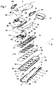
10 Referring to Figures 1 to 3, a medication dispenser according to a
preferred
embodiment of the invention comprises a case 1 formed of a bottom part 2 and
of
a top part 3 assembled together. The case 1 extends in a longitudinal
direction D
and has two open ends, referred to as front end 4 and rear end 5, a top wall
6, a
bottom wall 7 and two longitudinal side walls 8. Inside the case 1 are
provided a
rigid chassis 9, a foam plate 10, an array of blisters 11, an upper plate 12,
a
movable actuating member 13 and a movable driving member 14 for driving the
actuating member 13. A removable end cap 15 closes the front end 4 of the
case 1. An enlarged end portion 16 of the driving member 14 closes the rear
end 5
of the case 1.
The chassis 9 is fixed to the case 1 and has a frame 17 in which a base
support plate 18 having an array of through holes 19 is fixed. Typically, the
array
of through holes 19 defines side-by-side longitudinal rows of through holes
19, i.e.
rows that extend side-by-side in the longitudinal direction D, and side-by-
side
lateral rows of through holes 19, i.e. rows that extend side-by-side in a
direction
orthogonal to the longitudinal direction D. In the example shown, two
longitudinal
rows of five through holes 19, or in other words five lateral rows of two
through
holes 19, are provided. The base support plate 18 may be a separate part
assembled to the frame 17 or may be integrally formed with the frame 17. The
lower face of the chassis 9 defines longitudinal separate recesses 20 (see
Figures
CA 02737454 2011-03-16
WO 2010/055377 PCT/IB2009/007006
11
1 and 5) respectively located below the longitudinal rows of through holes 19
in
order to communicate each with the through holes 19 of the respective row. The
rear end 21 of each recess 20 is closed. The front end 22 of each recess 20 is
open so as to communicate with the inside of the end cap 15. The recesses 20
and the bottom wall 7 form together longitudinal cavities which communicate
with
the inside of the end cap 15. A ring 23 (visible in Figure 8), typically of
metal, is
fixed to the internal face of each through hole 19 of the base support plate
18,
coaxially with the through hole 19. Each ring 23 has a cutting edge 24
extending
as an arc of a circle and projecting upwards from the upper face of the base
io support plate 18. The cutting edge 24 may have teeth, as shown.
The foam plate 10 rests on the upper face of the base support plate 18. The
foam plate 10 may be fixed to the base support plate 18, for example by
gluing.
The foam plate 10 has an array of through holes 25 respectively aligned
vertically
with the through holes 19 of the base support plate 18. Each through hole 25
of
the foam plate 10 receives the projecting cutting edge 24 of the respective
ring 23.
The blisters 11 each include a medication dose 26 in the form of a tablet, a
pill, a capsule or the like. The blisters 11 are disposed on the upper face of
the
foam plate 10 so as to be vertically aligned with the through holes 25, 19 of
the
foam plate 10 and the base support plate 18. In the example shown, the
blisters
11 are arranged as several separate blister packs 27 each forming one lateral
row
of blisters. Providing the blisters in small separate blister packs, as is
shown,
facilitates the management of the quantities of medication and permits
reducing
medication wastage. In a variant, however, a single larger blister pack could
be
provided on the foam plate 10 to form the array of blisters.
The upper plate 12 is placed above the foam plate 10 and the flat part,
referenced 27a, of the blister packs 27, and is retained in the frame 17 of
the
chassis 9 for example by elastically deformable members projecting from the
inner
face of the frame 17. The upper plate 12 has an array of through holes 28
vertically aligned with the through holes 19, 25 of the support and foam
plates 18,
CA 02737454 2011-03-16
WO 2010/055377 PCT/IB2009/007006
12
and in which the blisters 11 are received. The upper plate 12 carries pressing
members 29 that take the form of tabs projecting obliquely upward and forward
from the upper plate 12 and that are hinged at one end to the upper plate 12.
As
shown in Figures 4 and 8, the pressing members 29 may be integrally formed
with
5 the upper plate 12 and the hinges, referenced 30, may be elastic hinges
formed by
thin portions of the upper plate 12. The pressing members 29 are associated
with
the through holes 28 and the blisters 11. The free end of each pressing member
29 comprises an abutment member 31 of greater thickness than the rest of the
pressing member 29 and which rests against the top of the respective blister
11
10 due to the elastic force exerted by the hinge 30.
The upper plate 12 is more precisely formed of several rigid plate elements
32 connected to one another through flexible attachment members 33, as shown
in Figure 4. Each plate element 32 comprises one lateral row of the through
holes
28 and the respective pressing members 29. The plate elements 32 are thus
movable relative to one another. In particular, each plate element 32 may be
moved downward, causing the foam plate 10 to be compressed, independently of
the other plate elements 32.
Referring back to Figures 1 and 2, the driving member 14 has two lateral
longitudinal guiding members 34 which project from the enlarged end portion 16
and maintain the driving member 14 in the case 1 while allowing it to move
longitudinally forward (i.e. in the direction D) and backward (i.e. in the
direction
opposite to the direction D) relative to the case 1 between a rest position
(shown in
Figure 5) where the enlarged end portion 16 closes the rear end 5 of the case
1
and a pulled position (shown in Figure 6) where the enlarged end portion 16 is
distant backward from the read end 5. In the rest position of the driving
member
14, part of the upper face and of the lower face of the enlarged end portion
16 is
exposed through recesses 35 formed in the rear end 5 to enable the, user to
seize
the enlarged end portion 16. In both the rest and pulled positions of the
driving
member 14, the blisters 11 remain inaccessible to the user. To this effect,
the
CA 02737454 2011-03-16
WO 2010/055377 PCT/IB2009/007006
13
driving member 14 has an upper wall 36 between the guiding members 34 and
next to the enlarged end portion 16. This upper wall 36 prevents access to the
inside of the case 1 from the upper side of the driving member 14. Access from
the
lower side of the driving member 14 is prevented by a similar lower wall of
the
driving member 14 and/or by an end rear wall 37 of the chassis 9. The guiding
members 34 each comprise first and second wall extensions 38, 39 oriented
downward and separated by a recess 40. The extensions 38, 39 of each guiding
member 34 are guided in a respective lateral longitudinal groove 41 formed in
or at
a lateral wall of the case bottom part 2. A stop member (not shown), such as a
io screw, a pin or the like, is fixed laterally in each of the lateral walls
of the case
bottom part 2 so as to be located in the recess 40 between the wall extensions
38,
39 and thus in the path of the guiding member 34. These stop members limit the
motions of the driving member 14, by being abutted by the second wall
extensions
39 to prevent the driving member 14 from being pulled beyond the said pulled
position, and by being abutted by the first wall extensions 38 to prevent the
driving
member 14 from being pushed beyond the rest position. In the rest position of
the
driving member 14, alternatively to the abutment of the first wall extensions
38
against the stop members, the enlarged end portion 16 of the driving member 14
may abut against the rear end 5 of the case 1 or against the end wall 37 of
the
chassis 9.
The actuating member 13 is disposed on the upper plate 12 and retained
vertically by upper walls 42 of the guiding members 34. The actuating member
13'
comprises lateral tabs 43 in its rear portion which cooperate with notches 44
provided in the inner faces of the guiding members 34. Each notch 44 (see
Figure 2) is defined by a laterally-oriented surface 45 and an inclined
surface 46
forming an angle together, with the inclined surface 46 being located forward
to
the laterally-oriented surface 45. The notches 44 and tabs 43 form indexing
means
defining determined successive rest longitudinal positions for the actuating
member 13. The actuating member 13 is held in each of said rest positions by
the
CA 02737454 2011-03-16
WO 2010/055377 PCT/IB2009/007006
14
free ends of the tabs 43 being each blocked substantially at the edge of
intersection between the two surfaces 45, 46 of one notch 44. The notches 44
and
the tabs 43 also form a detent mechanism that moves the actuating member 13
longitudinally forward by one step, i.e. from one rest position to the next,
when the
driving member 14 is pushed from its pulled position to its rest position and
that
enables the driving member 14 to be pulled from its rest position to its
pulled
position without moving the actuating member 13. The laterally-oriented
surfaces
45 of two opposite notches 44 of the respective guiding members 34 indeed form
abutment surfaces which push the actuating member 13, more precisely the free
end of the tabs 43, when the driving member 14 is pushed from its pulled to
its rest
position. The inclined surfaces 46 of two opposite notches 44 of the
respective
guiding members 34 form sliding surfaces which slide on the free end of the
elastic
tabs 43 while elastically deforming the tabs 43 inward when the driving member
14
is pulled from its rest position to its pulled position. To hold the actuating
member
13 in place relative to the upper plate 12, chassis 9 and case 1 when the
driving
member 14 is being pulled, projections 47 are provided on the inner upper face
of
the case top part 3, which cooperate with tabs 48 (see Figure 6) provided at
the
rear of the actuating member 13. The projections 47 have a vertical abutment
surface 49 (see Figure 8) for cooperating with the tabs 48 to block the
actuating
member 13 in the backward direction, and an inclined cam surface 50 which
allows the actuating member 13 to move forward by causing an elastic downward
deformation of the tabs 48. The stroke of the driving member 14 between the
rest
and pulled positions is equal to the distance between two adjacent notches 44
and
to the distance between two adjacent through holes 28 (two adjacent blisters
11)
in the longitudinal direction D.
The actuating member 13 further comprises pressing members 51 (best
visible in Figures 5-7 and 8-12) which project longitudinally forward from the
body
of the actuating member 13 and which are laterally offset relative to the
pressing
members 29 and the through holes 28 of the upper plate 12 so as not to
interfere
CA 02737454 2011-03-16
WO 2010/055377 PCT/IB2009/007006
with the pressing members 29 and the through holes 28 during motion of the
actuating member 13. In the example shown, three pressing members 51 are
provided, respectively between one lateral longitudinal side of the upper
plate 12
and one longitudinal row of through holes 28, between the two longitudinal
rows of
5 through holes 28, and between the other longitudinal row of through holes 28
and
the other lateral longitudinal side of the upper plate 12. The pressing
members 51
are hinged to the body of the actuating member 13. As shown in Figure 8, the
pressing members 51 may be integrally formed with the body of the actuating
member 13 and elastically hinged to it through a thinner portion 52. The free
end
io of each pressing member 51 is thicker than the base portion next to the
hinge 52,
and has an inclined surface 53 in its upper portion and a lower rounded
surface 54
in contact with the upper plate 12.
Besides the function of retaining the actuating member 13 when the driving
member 14 is being pulled, the projections 47 have a function of actuating the
15 pressing members 51, as will be explained later. The projections 47 are
arranged
in longitudinal rows which are laterally aligned to one another and
longitudinally
aligned, respectively, with the pressing members 51. In the example shown, two
lateral longitudinal rows of projections 47 are used for both functions and
one
central longitudinal row of projections 47 is used for the second function
only.
Each lateral row of the projections 47 is associated with one lateral row of
blisters 11.
The actuating member 13 further comprises pressing surfaces 55 which are
aligned, respectively, with the longitudinal rows of the pressing members 29.
Each
pressing surface 55 comprises a horizontal rearward surface portion 56 which
rests and slides on the upper plate 12 and a forward surface portion 57 that
is
inclined forward and upward from the rearward surface portion 56.
The dispenser according to the invention operates as follows. To release
medication doses 26 from a lateral row of blisters 11, the user pulls the
driving
member 14 relative to the case 1 from its rest position to its pulled position
CA 02737454 2011-03-16
WO 2010/055377 PCT/IB2009/007006
16
(Figure 6). The actuating member 13 does not move during this rearward motion
of the driving member 14, since it is retained by the abutment surfaces 49 of
the
projections 47. The tabs 43 however are deformed inward by the inclined
surfaces
46 of one pair of opposite notches 44 of the guiding members 34, and return
into
their non-deformed rest condition when the next pair of opposite notches 44
reaches them, which corresponds to the pulled position of the driving member
14.
Then, the user pushes the driving member 14 back to its rest position (Figure
7),
which causes the laterally-oriented surfaces 45 of said next pair of opposite
notches 44 to cooperate with the tabs 43 of the actuating member 13 to push
the
actuating member 13 by one step forward. During this one-step forward motion
of
the actuating member 13, the pressing members 51 come into contact with one
lateral row of projections 47, which causes the inclined cam surfaces 50
thereof to
cooperate with the inclined surfaces 53 of the pressing members 51 to move the
pressing members 51 downward by elastic deformation of the hinges 52 (Figures
9, 10), thereby moving the corresponding upper plate element 32 downward by
compressing the foam plate 10. The downward motion of the upper plate element
32 brings the sealant film of the corresponding blisters 11 into contact with
the
cutting edge 24 of the corresponding rings 23. The cutting edge 24 pre-cuts
the
.sealant film in the zone of the corresponding blisters 11. Still in this one-
step
forward motion of the actuating member 13, after the pressing members 51 have
left contact with the inclined surfaces 50, they are returned into their rest,
horizontal position by the elastic hinges 52 (Figure 11). Next, the inclined
forward
surface portions 57 and then the horizontal rearward surface portions 56 of
the
actuating member 13 come into contact with the pressing members 29 and urge
them down to press and collapse the blisters 11 (Figure 12). The medication
doses 26 are expelled from the blisters 11 through the already punctured
sealant
film and fall into the cavities defined by the recesses 20 and the case bottom
part 2. The one-step forward motion of the actuating member 13 is completed
after
all these operations, i.e. puncturing the blister film and expelling the
medication
CA 02737454 2011-03-16
WO 2010/055377 PCT/IB2009/007006
17
doses 26 of one lateral row of blisters 11, have been made. By inclining the
dispenser, the user makes the medication doses 26 fall by gravity into the cap
15
which communicates with the aforementioned cavities. Next, the user removes
the
cap 15 with the medication doses 26 in it and can bring the medication doses
26
into his/her mouth without touching them with the hands. The same sequence of
operations as above will later be performed to release the medication doses 26
from the next lateral row of blisters 11, and so on.
Thus, expelling the medication doses 26 from one lateral row of blisters 11
merely requires a first, linear pulling action and a second, linear pushing
action on
io the driving member 14. Due to its size, the enlarged end 16 of the driving
member
14 may be easily seized. The pulling action may be easily performed with one
hand while holding the case 1 with the other hand. The pushing action may be
performed similarly, or with one hand only, for example by setting the
dispenser
orthogonally to a surface, such as a table surface or a wall surface, and by
pressing the driving member 14 while the front end of the dispenser (defined
by
the cap 15) is resting on that surface. A low dexterity is sufficient to
perform the
sequence of the pulling and pushing actions. Moreover, this sequence remains
the
same irrespective of the position of the actuating member 13 in the case 1.
Thus,
the user need not know how many blisters 11 have already been collapsed before
operating the dispenser.
In an advantageous variant of the invention, the pressing surfaces 55 of the
actuating member 13 are longitudinally offset as shown in Figure 13 so that
during
a one-step motion of the actuating member 13 the blisters 11 of the
corresponding
lateral row of blisters 11 are collapsed successively. This configuration
reduces
the force required from the user to expel each medication dose 26. In another
variant, the pressing surfaces 55 could be laterally aligned and the
longitudinal
rows of blisters 11 could be longitudinally offset.
The bottom case part 2 may be made transparent to allow the user to see
which blisters 11 have already been collapsed and hence how many medication
CA 02737454 2011-03-16
WO 2010/055377 PCT/IB2009/007006
18
doses are left in the dispenser. In a variant or additionally, as shown in
Figures 1
and 3, the top case part 3 may have at least one window 58 at each of the
determined rest positions of the actuating member 13 and the actuating member
13 or part of it may be of a specific colour, for example red, different from
the
colour of the top case part 3 so that the position of the actuating member 13
is
indicated by the window(s) 58 through which that specific colour is visible.
The
windows 58 may be in the form of through holes provided in the top wall 6, as
shown.
Besides the above-mentioned advantages, the dispenser according to the
invention is advantageous in that it always keeps a limited size, in that the
risks of
squeezing the user's fingers upon manipulation by the user are low, and in
that the
blisters are inaccessible, which provides a protection for people who should
not be
in contact with the medication, in particular children, as well as for the
patient
himself in the case where the medication has a high degree of toxicity and
must
is not be contacted by the skin. The dispenser according to the invention is
most
preferably used for anti-cancer drugs, drugs having an immediate toxic effect
of
drugs having an effect on the immune system, such as purine analogues, in
particular Cladribine or derivatives thereof. Cladribine is a chlorinated
purine
analogue which has been suggested to be useful in the treatment of multiple
sclerosis (EP 626 853) and cancer.
Typically, the dispenser according to the invention is for single use. Once
all
blisters 11 are empty, the dispenser is disposed of. The dispenser, more
precisely
the bottom and top case parts 2, 3, the chassis 9, the upper plate 12, the
actuating
member 13, the driving member 14 and the removable end cap 15, may be made
of metal or of a synthetic material, such as an organic polymer.
The number of blisters 11 in the dispenser may of course vary. The array of
blisters 11 could include one longitudinal row, instead of two as shown, or
more
than two longitudinal rows depending on the posology for which the dispenser
is
conceived. The dispenser could even include a single blister. The number of
CA 02737454 2011-03-16
WO 2010/055377 PCT/IB2009/007006
19
through holes 19, 25, 28 and pressing members 29, 51 would of course be
adapted to the number of blisters 11 required. However, one could select a
standard size for the dispenser and a standard number of through holes 19, 25,
28
and pressing members 29, 51 and the number of blisters 11 would be either
equal
to or lower than the number of through holes 19, respectively 25, respectively
28,
and pressing members 29 depending on the posology.
In a variant, the upper plate 12 could be entirely rigid, instead of being
made of several hinged rigid elements 32, and the foam plate 10 and the
cutting
rings 23 could be removed. The cutting rings 23 are not necessary but they
permit
io the use of smaller sized pressing members 29 and actuating member 13 by
reducing the force required to expel the medication doses 26 from the blisters
11.
Also, the pressing members 29 or the inclined forward surface portions 57
could be removed.
A same pressing member 29, extending laterally, could be used for each
lateral row of blisters 11.
Moreover, the stroke of the driving member 14 could be increased so that a
one-step motion of the actuating member 13, caused by one pulling action
followed by one pushing action on the driving member 14, causes the medication
doses in several lateral rows of blisters to be expelled.
Advantageously, to confer a further protection for people who should not be
in contact with the medication, in particular children, the dispenser
according to the
invention comprises a locking mechanism which locks the driving member 14 in
its
rest position to prevent the release of medication doses 26. The locking
mechanism comprises buttons which must be operated according to a specific
sequence to unlock the driving member 14. In the example shown (see Figure 3),
these buttons include opposite push buttons 60 provided in respective openings
in
the side walls 8 of the case 1 and a slide button 61 provided in an opening in
the
top wall 6 of the case 1. The term "button" is to be understood here in a
broad
sense, as covering any part on which a finger can rest to transmit a force.
The
CA 02737454 2011-03-16
WO 2010/055377 PCT/IB2009/007006
specific sequence of operations to be performed to unlock the driving member
14
is the following :
- operate the slide button 61 as shown by arrow 62 in Figure 14,
- then operate the lateral push buttons 60 as shown by arrows 63 in
5 Figure 15 while maintaining the slide button 61 in its operated position,
- and then pull the driving member 14 as shown by arrow 64 while
maintaining the lateral push buttons 60 in their operated position.
Once the lateral push buttons 60 are operated, the user may release the slide
button 61. Maintaining the lateral push buttons 60 in their operated position
is
10 required only at the beginning of pulling the driving member 14, to unlock
the
latter. Then the driving member 14 may be freely moved toward its pulled
position
without maintaining pressure on the push buttons 60. Typically, the dispenser
is
held in one hand with the thumb and another finger of the hand acting on the
lateral push buttons 60 and a finger of the other hand acting on the top slide
button
15 61, the said other hand being used to pull the driving member 14 after
releasing
the top slide button 61.
It will thus be appreciated that three actions have to be performed by the
user, in a determined order, to unlock the driving member 14. As will be
explained
below, operating the lateral push buttons 60 while the slide button 61 is not
in its
20 operated position is not possible because the slide button 61, in its rest
position,
blocks the lateral push buttons 60 and prevents them from moving beyond an
intermediate pressed position in which the driving member 14 is still locked.
Operating the slide button 61 while a pressure is applied on one or two of the
lateral push buttons 60 is not possible either, because the lateral push
buttons 60,
in their intermediate pressed position, block the slide button 61. Merely
operating
the slide button 61 frees the lateral push buttons 60 but does not free the
driving
member 14. Simultaneous pressure holding on the operated lateral push buttons
60 and pulling action on the driving member 14 are required to unlock the
driving
member 14.
CA 02737454 2011-03-16
WO 2010/055377 PCT/IB2009/007006
21
A child will generally not have the manual dexterity nor the cognitive
knowledge to perform the above-described sequence of operations required to
unlock the driving member 14. Moreover, the case 1 may be made sufficiently
wide for the lateral buttons 60 to be separated by a large distance, thereby
making
s it impossible for a child to hold the dispenser in one hand and to press the
lateral
buttons 60 while holding the slide button 61 in its operated position or to
pull the
driving member 14 while pressing the lateral buttons 60.
The internal mechanism allowing the above-described sequence of
operations is diagrammatically shown in Figures 16 to 19. The slide button 61
projects from and is rigidly connected to a plate 65 that is slidably guided
in the
case 1 above the blisters 11 and the actuating member 13 in a direction
parallel to
the longitudinal direction D of the dispenser. A return spring 66 is provided
between the rear end of the plate 65 and a bearing part 67 rigidly connected
to the
inner face of the top wall 6 of the case 1. The return spring 66 may be a leaf
spring
made of one-piece construction with the plate 65 and the button 61, as shown.
Alternatively, it could be a conventional metal leaf or helical spring
disposed
between the rear end of the plate 65 and the bearing part 67. The two sides 68
of
the plate 65 along the longitudinal direction D of the dispenser include
respective
opposite holes 69 and, between the holes 69 and the rear end of the plate 65,
respective stop projections 70.
Each lateral push button 60 is part of a piece 71 comprising, inside the
case 1, a locking part 72 and a return U-bent leaf spring 73 extending between
a
corresponding side 68 of the plate 65 and the button 60. The piece 71 is held
by a
part 74 rigidly connected to the case 1. The locking part 72 comprises a stop
projection 75 extending inwardly in the lateral direction and a locking member
76
extending outwardly in the lateral direction. The locking member 76 engages a
corresponding locking member 77 of the driving member 14 to lock the driving
member 14, as is shown in Figure 16. The locking member 77 extends inwardly in
the lateral direction and is located at the end of an arm 78 of the driving
member
CA 02737454 2011-03-16
WO 2010/055377 PCT/IB2009/007006
22
14. The stop projection 75 has two functions. A first function is to come into
abutment against the corresponding side 68 of the plate 65 when the push
button
60 is pressed and the slide button 61 is in its rest position, shown in Figure
16, to
prevent the piece 71 and the push button 60 from going beyond the
aforementioned intermediate pressed position in which the locking member 76
still
engages the locking member 77, in other words to prevent disengagement of the
locking members 76, 77. The second function is to block the stop projection 70
when the slide button 61 is moved toward its operated position while the push
button 60 is held in its intermediate pressed position, thereby preventing the
slide
io button 61 from reaching its operated position.
When the push buttons 60 are in their rest position, the stop projections 75
do not interrupt the paths of the stop projections 70 and therefore do not
hinder the
movement of the slide button 61, which can thus be moved up to its operated
position. When the slide button 61 is in its operated position (Figure 17),
the stop
projections 75 face the holes 69. In this configuration, if the lateral push
buttons 60
are pressed, the stop projections 75 will enter the holes 69, enabling the
pieces 71
and push buttons 60 to go beyond the aforementioned intermediate position and
to
reach their operated position, shown in Figure 18. In this operated position,
the
locking members 76 are out of engagement with the locking members 77 and the
driving member 14 is therefore free. The driving member 14 may thus be slid
out
to reach its pulled position (Figure 19). The sides 68 of the plate 65, with
their
holes 69 and their surfaces of contact with the stop projections 75, thus
constitute
locking means serving to prevent the locking members 76 from disengaging with
the locking members 77 or to enable such a disengagement.
So long as the lateral push buttons 60 are held in their operated position,
the slide button 61 is blocked in its operated position due to the cooperation
between the stop projections 75 and the holes 69. Once the buttons 60 have
been
released by the user, they are returned to their respective rest positions by
the
springs 73. The driving member 14 may be returned to its locked rest position,
to
CA 02737454 2011-03-16
WO 2010/055377 PCT/IB2009/007006
23
expel medication doses 26 from blisters 11, merely by pushing it forward.
Internal
faces of the side walls 8 of the case 1 have recesses 79. The locking members
76,
77 have inclined surfaces 80, 81 (see Figure 16) that cooperate when the
driving
member 14 is pushed forward while the buttons 60 are in their rest position,
causing the arms 78 of the driving member 14 to deform externally into the
recesses 79 until the locking members 77 recover their locked position in
which
they engage the locking members 76.
In a variant of the invention, the lateral push buttons 60 could be of one-
piece construction with the case 1 and could be in the form of tabs defined by
cut-
io outs made in the side walls 8 of the case 1 and elastically hinged to the
rest of the
case 1.