Note: Descriptions are shown in the official language in which they were submitted.
CA 02737462 2011-03-16
WO 2010/036584 PCT/US2009/057607
1
WRAPPER HAVING A CORD RESERVOIR
FIELD OF THE INVENTION
The invention relates to wrappers for feminine devices, and more particularly
to wrappers
for feminine devices having a cord reservoir.
BACKGROUND OF THE INVENTION
Feminine devices, such as tampons and pessaries, are generally used by women
within
the vagina for feminine needs, such as, for example, to absorb menstrual or
other body exudates,
for pelvic support, and/or for other feminine needs. Such feminine products
can be inserted into
the vagina by using an applicator, or can be inserted digitally using a
finger. Typically, these
types of feminine products can be removed after use when the user pulls a
withdrawal member
attached to the tampon.
Feminine devices can be individually packaged. Individual packaging can
improve
hygiene, for example, by keeping the devices from being soiled by dust,
unintended touching,
and the like. The individual packaging can include a wrapper, such as a
wrapper made of plastic
film. Digital tampons, for example, can be tightly packaged in wrappers that
can assist in
sustaining the shape of the enclosed tampon over time under possible changes
of temperature
and/or humidity, in addition to facilitating ease of carrying the tampon
before use.
A user may prefer that this withdrawal cord remain easily accessible during
use, such that
the user can easily grasp the string when she is ready to remove the tampon.
In the case of
applicator tampons, the withdrawal cord can be extended through the plunger,
for example.
Digital tampons, on the other hand, typically require that the withdrawal
member be compressed
against and/or into the tampon body so that the tampon and cord can be tightly
packed within the
wrapper. When the user opens and removes the wrapper to prepare the tampon for
insertion, the
withdrawal cord can remain compacted and/or can be tangled. The user may have
to unpack the
withdrawal cord and search for the end of it in order to extend the cord prior
to insertion.
As such, it would be desirable to provide a wrapper such as, e.g., a wrapper
for a feminine
device, with improved withdrawal cord management.
SUMMARY OF THE INVENTION
Wrappers having cord reservoirs are provided. A feminine device having an
insertion
end, a withdrawal end, and a withdrawal member, the withdrawal member having a
proximal end
CA 02737462 2011-03-16
WO 2010/036584 PCT/US2009/057607
2
nearest the withdrawal end of the feminine device and a distal end disposed
opposite the
proximal end is provided. The feminine device can be at least partially
enclosed by a wrapper.
The wrapper can have a first end disposed adjacent to the insertion end, a
second end opposite
the insertion end, and a longitudinal axis. In certain embodiments, the
wrapper can have a cord
reservoir at the second end of the wrapper, the cord reservoir being adapted
to contain at least a
portion of the withdrawal member within the cord reservoir. In addition, the
cord reservoir can
have a length measured along the longitudinal axis from the distal end of the
feminine device to
the second end of the wrapper of at least about 1 mm. In certain embodiments,
the withdrawal
member can have a withdrawal element releasably joined to the distal end.
A method for making a wrapped feminine device is also provided.
BRIEF DESCRIPTION OF THE DRAWINGS
Figure 1 is a plan view of a wrapped tampon.
Figure 2 is a plan view of a wrapped tampon.
Figure 3 is a plan view of a wrapped tampon.
Figure 4 is a plan view of a wrapped tampon.
DETAILED DESCRIPTION OF THE INVENTION
The present invention relates to a wrapper having a cord reservoir. The
wrapper can at
least partially enclose a feminine device, such as, e.g., a tampon or pessary.
In certain
embodiments, the feminine device can have a withdrawal member and the wrapper
can include a
cord reservoir that can enclose at least part of a withdrawal member. In
addition, in certain
embodiments, the wrapper can include a cord reservoir that is adapted to
enclose the withdrawal
member.
Preparing a feminine device for insertion can represent a major part of a
user's experience
with the device. Therefore, if the feminine device is difficult to prepare for
insertion, such as,
e.g., enclosed in a wrapper that can be difficult to remove, or with a tightly
packed withdrawal
cord, a user's experience can be adversely affected. For example, digital
tampons can include a
withdrawal member that can be compacted, e.g., wound, looped, folded,
entangled, or the like,
when the tampon is contained in the wrapper. The withdrawal member can need to
be deployed,
e.g., stretched, straightened, loosened, unraveled, disentangled, or the like,
by a user after
wrapper removal and prior to insertion of the device. Grasping the withdrawal
member can be
awkward and can disrupt hygienic device handling due to the user touching the
device with their
CA 02737462 2011-03-16
WO 2010/036584 PCT/US2009/057607
3
fingers while the user tries to prepare the device. As such, wrappers of the
present invention can
provide an improved experience to a user, such as, e.g., by improving
deployment of the
withdrawal member and/or by improving the user's wrapper removal experience.
As used herein, the term "feminine device" includes devices useful for
feminine needs,
such as, e.g., incontinence articles and absorbent articles useful for
feminine needs, such as
articles that typically can be intended for feminine use internally, such as,
e.g., within a user's
vagina. Internal feminine devices can include, for example, tampons,
pessaries, and
contraceptive devices.
As used herein, the term "tampon" refers to any type of absorbent structure
that can be
inserted into the vaginal canal or other body cavity, such as, e.g., for the
absorption of fluid, to
aid in wound healing, and/or for the delivery of materials, such as moisture
or active materials
such as medicaments.
As used herein, the term "vaginal canal" refers to the internal genitalia of
the human
female in the pudendal region of the body. The terms "vaginal canal" or
"within the vagina" as
used herein are intended to refer to the space located between the introitus
of the vagina
(sometimes referred to as the sphincter of the vagina) and the cervix.
As used herein, "applicator" refers to a device or implement that facilitates
the insertion
of a feminine device, such as, e.g., a tampon or pessary, into an external
orifice of a mammal,
such as, e.g., the vaginal canal. Exemplary applicators include telescoping,
tube and plunger, and
compact applicators.
As used herein, the term "digital tampon" refers to a tampon that is intended
to be
inserted into a vagina with a user's finger and generally without aid of an
applicator.
As used herein, the term "pessary" refers to any type of structure for the
purpose of
reducing urine leakage and/or supporting a prolapsed uterus and/or bladder.
Such pessaries can
have any variety of shapes and sizes including cylinder, ovate, spherical,
tubular, annual rings,
"U" shaped, cup shaped, rings, cubes or donut shaped, and can function in any
suitable manner,
such as, e.g., by direct application of support, lever force, expansion of the
device by selection of
material, and/or by inflation of the device.
As used herein, the term "wrapper" refers to a structure that can be formed of
one or more
wrapper materials and can at least partially enclose one or more devices, such
as, e.g., a tampon
and/or pessary, for packaging purposes. It can be constituted of one connected
piece of one or
more wrapper materials or it can be made from multiple pieces of one or more
wrapper materials
that can be joined together.
CA 02737462 2011-03-16
WO 2010/036584 PCT/US2009/057607
4
As used herein, the term "fixedly joined" refers to a connection that is not
meant to be
easily released, such as, e.g., a connection formed using a substantially
permanent seal and/or a
connection that cannot be unattached without at least partially destroying one
of the attached
components.
As used herein, the term "releasably joined" refers to a connection that is
meant to be
easily released.
As used herein, the term "associated" refers to two elements that are near but
not
connected, such as, for example, two elements that may be touching but not
joined.
As used herein, the term "insertion end" refers to the portion of the feminine
device
including the end that is intended to enter the vaginal canal first when
inserting the feminine
device into the vaginal canal.
As used herein, the term "withdrawal end" refers to the portion of the
feminine device
opposite the insertion end. In certain embodiments, the withdrawal end can
include the end is
intended to exit the vaginal canal first when the feminine device is removed
from the vagina.
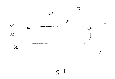
Figure 1 shows one embodiment of a prior art wrapper 10. The wrapper 10 has a
first end
11 and a second end 12. As shown in Figure 1, the wrapper 10 can at least
partially enclose a
tampon 30. The tampon 30 can have an insertion end 31, a withdrawal end 32,
and a withdrawal
member 33. The withdrawal member 33 is tightly packed against the body of the
tampon 30.
Figure 2 shows one embodiment of a wrapper 10. The wrapper 10 has a first end
11 and
a second end 12. As shown in Figure 2, the wrapper 10 can at least partially
enclose a tampon
30. The tampon 30 can have an insertion end 31, a withdrawal end 32, and a
withdrawal member
33. The wrapper 10 has a cord reservoir 14. As shown in Figure 2, the
withdrawal member 33 is
loosely packed within cord reservoir 14.
Figures 3 and 4 show embodiments of a wrapper 10. The wrapper 10 has a first
end 11
and a second end 12. The wrapper 10 can at least partially enclose a tampon
30. The tampon 30
can have an insertion end 31, a withdrawal end 32, and a withdrawal member 33.
The wrapper
10 has a cord reservoir 14. As shown in Figures 3 and 4, the withdrawal member
33 can be
loosely packed within cord reservoir 14. In addition, in certain embodiments,
the withdrawal
member 33 can include a releasably joined withdrawal element 34, such as, for
example, a bead,
a bow, or other suitable element. The withdrawal element 34 can be pulled to
extend withdrawal
member 33, after which withdrawal element 34 will disconnect from withdrawal
member 33. In
certain embodiments, withdrawal element 34 can then be discarded along with
wrapper 10. In
addition, as shown in Figure 3, withdrawal element 34 can be packaged along
with withdrawal
CA 02737462 2011-03-16
WO 2010/036584 PCT/US2009/057607
member 33 within cord reservoir 14. Alternatively, as shown in Figure 4, a
portion of
withdrawal member 33 can protrude through wrapper 10 allowing withdrawal
element 34 to be
positioned outside the wrapper 10, such as, e.g., on the exterior of wrapper
10. In certain
embodiments, the withdrawal element 34 can also function as an opening device.
5 The cord reservoir can have any suitable size. In certain embodiments, the
cord reservoir
can be provided at the withdrawal end of the tampon and can include a length
measured along the
longitudinal axis of the wrapper. The length can be any suitable length, such
as, for example,
greater than about 1 mm, such as, e.g., from about 1 mm to about 10 mm, from
about 2 mm to
about 8 mm, from about 3 mm to about 6 mm, from about 4 mm to about 5 mm, or
any other
suitable length. In addition, the cord reservoir can have any suitable width
measured
perpendicular to the length. For example, in certain embodiments, the cord
reservoir can have a
width approximately equal to the width of the tampon, or any other suitable
width.
Any suitable amount of the withdrawal member can be disposed within the cord
reservoir.
For example, in certain embodiments, at least about 20%, at least about 30%,
at least about 40%,
at least about 50%, at least about 60%, at least about 70%, at least about
80%, at least about 90%,
and/or substantially the entire withdrawal member can be disposed within the
cord reservoir. In
certain embodiments, the distal end of the withdrawal member can be disposed
within the cord
reservoir.
The wrapper can include any suitable opening device. Suitable opening devices
include,
e.g., one or more perforations, such as, e.g., disclosed in U.S. Patent No.
6,955,665, one or more
depressions, such as, e.g., disclosed in European Patent No. EP 597446, a tear
tape, a line of
sealing, such as, e.g., disclosed in U.S. Patent No. 4,648,513, and the like.
In certain
embodiments, the one or more opening devices can be provided around at least a
portion of a
perimeter or a length of the wrapped feminine device.
The wrapper material used can be any material suitable for use for wrapping a
feminine
device. Suitable wrapper materials include, e.g., plastic films made of
cellophane, polyethylene,
polypropylene, polyester, polystyrene, PET (polyethylenetherephthalate),
polyamide,
polyvinylchloride, ethylene-vinyl acetate copolymer and the like; synthetic or
natural elastomers,
e.g., rubber; generally occlusive materials such as metallic foils, e.g.,
aluminum foil; non-
occlusive or porous materials, such as nonwoven materials, woven materials,
scrims, meshes, and
papers; or any other suitable materials. In certain embodiments, the wrapper
can include one or
more flexible polymeric films, such as, for example, films having a thickness
of less than about 1
mm.
CA 02737462 2011-03-16
WO 2010/036584 PCT/US2009/057607
6
The wrapper can be made using any suitable technique, including, for example,
heat-
shrinking, heat sealing, adhesives, pressure, stretching, lamination, coating,
gluing, embossing,
crimping, sewing, stitching, entangling, mechanical interlocking, cold
pressure welding,
ultrasonic bonding, and/or combinations thereof.
The wrapper can include one or more tabs. Suitable tabs include, e.g., tabs
set forth in,
e.g., U.S. Patent Nos. 4,648,513; 5,133,457; and 6,955,665. A tab of a wrapper
of the present
invention can have any suitable shape, such as e.g., a flap, a strip, a cord,
a twist, a flare, a frill, a
fringe, a ribbon, a loop, or the like. It can be constructed as part of the
wrapper material and/or by
attaching an additional material to the wrapper. It can be formed using any
suitable technique,
including, for example, pressing, heat sealing, adhesives, gluing, lamination,
embossing,
crimping, sewing, stitching, entangling, raveling, twisting, folding,
mechanical interlocking,
welding, ultrasonic bonding, fusing, and/or combinations thereof.
The feminine device can have a withdrawal member. The withdrawal member can be
any
suitable configuration, such as, e.g., one or more cords, strings, finger
covers, ribbons, an
extension of a material of the device, or combinations thereof. The withdrawal
member can be
made of any suitable material, such as, e.g., cotton and rayon. The withdrawal
member can
optionally be provided with a secondary absorbent member. Suitable secondary
absorbent
members are described in, e.g., U.S. Patent No. 6,258,075.
In certain embodiments, the withdrawal member can include a withdrawal
element. The
withdrawal element can be provided in any suitable location, such as, e.g., at
the distal end of the
withdrawal member. In certain embodiments, the withdrawal element can be
releasably attached
to the withdrawal member such that the withdrawal element can be disconnected
from the
withdrawal member prior to insertion of the feminine device by the user. The
withdrawal
element can be any suitable element, such as, e.g., a bead, a sparkle, a bow,
a gem, or any other
suitable element. In certain embodiments, the withdrawal element can also
function as an
opening device.
In certain embodiments, the feminine device can be a tampon. The tampon can
include a
pledget that can include a single material or a combination of materials. The
materials for the
tampon can be formed into a fabric, web, or batt that is suitable for use in
the tampon by any
suitable process such as, for example, airlaying, carding, wetlaying,
hydroentangling, or other
known techniques.
The pledget can be constructed from a wide variety of liquid-absorbing
materials
commonly used in absorbent articles. Such materials include, for example,
rayon (such as
CA 02737462 2011-03-16
WO 2010/036584 PCT/US2009/057607
7
GALAXY rayon (a tri-lobed rayon) or DANUFIL rayon (a round rayon), both
available from
Kelheim Fibres GmbH of Kelheim, Germany), cotton, folded tissues, woven
materials,
nonwoven materials, synthetic and/or natural fibers or sheeting, comminuted
wood pulp, which is
generally referred to as airfelt, foams, or combinations of these materials.
Examples of other
suitable materials include: creped cellulose wadding; meltblown polymers
including coform;
chemically stiffened, modified or cross-linked cellulosic fibers; synthetic
fibers such as crimped
polyester fibers; peat moss; foam; tissue including tissue wraps and tissue
laminates; or any
equivalent material or combinations of materials, or mixtures of these.
Additionally,
superabsorbent materials, such as superabsorbent polymers or absorbent gelling
materials can be
incorporated into the tampon.
The pledget can have any suitable shape, size, material, or construction prior
to
compression and/or shaping. For example, the pledget can include a rolled,
tubed, or flat
construction of an absorbent that can be a circle, an oval, a semi-circle, a
triangle, a chevron
shape, an H shape, a bow-tie shape, or any other suitable shape, such as,
e.g., shapes described in,
for example, U.S. Patent Nos. 3,738,364; 5,911,712; 6,740,070; 6,887,266; and
6,953,456.
In certain embodiments, all or a portion of the tampon can be compressed into
a
substantially cylindrical configuration, however, other shapes are possible.
These can include
shapes having a cross section or cross-section element that can be described
as rectangular,
triangular, trapezoidal, semi-circular, hourglass, or other suitable shapes.
In certain embodiments,
the tampon can have a radially compressed rolled construction. The tampon can
be constructed
by rolling and radially compressing a pledget. In addition, or alternatively,
the tampon can
include an asymmetric insertion end, such as, e.g., tampons disclosed in U.S.
Pat. Appln. Nos.
11/526,041 and 11/525,513.
In certain embodiments, the tampon can have a length extending between the
withdrawal
end and the insertion end. In such an embodiment, the tampon may have a
patterned impression
in the withdrawal end, the insertion end, or both. In addition, the body
portion of the tampon
may have substantially no patterned impression. According to certain
embodiments, a tampon
with a patterned end may have a body portion with creases formed during
compression of the
uncompressed pledget, but such creases may not be considered a patterned
impression. In
addition, the patterned impression can be one or more colors and/or can
include one or more
design elements and the one or more design elements can be the same or
different colors.
A tampon can comprise one or more overwraps. The overwrap can be any suitable
material, such as, for example, rayon, cotton, bicomponent fibers,
polyethylene, polypropylene,
CA 02737462 2011-03-16
WO 2010/036584 PCT/US2009/057607
8
other suitable natural or synthetic fibers known in the art, and mixtures
thereof. In certain
embodiments, the tampon can comprise an overwrap material that substantially
encloses the
compressed tampon. In certain embodiments, the overwrap can extend from the
withdrawal end
of the tampon.
In certain embodiments, the tampon can include a finger pocket and/or a finger
indent at
the withdrawal end of the tampon. Suitable finger pockets are described in,
for example, U.S.
Patent Application Serial No. 12/198,154, or U.S. Patent No. 6,283,952. In
addition, or
alternatively, the tampon can include an overwrap that extends from the
withdrawal end and
forms a finger cover. In certain embodiments, the tampon can include an
overwrap that extends
from the withdrawal end and forms an absorbent skirt. In addition, the excess
of the overwrap
can be at least partially disposed in a finger pocket or a finger indent and
can be pulled out to
provide a finger cover or an absorbent skirt when the user prepares the tampon
for insertion. In
certain embodiments, the excess of the overwrap can be joined with the
withdrawal cord and
disposed in the finger pocket or the finger indent along with the withdrawal
cord, such as, for
example, in U.S. Patent Appln. Serial Nos. 11/525,553 and 11/525,730.
The cord reservoir can be constructed in any suitable manner. For example, in
certain
embodiments, in the case of a tampon, the withdrawal member can then be
bundled about the
base of the tampon during the tampon formation process. In certain
embodiments, a finger
pocket can be formed by applying a compression member either directly to the
base of the
tampon or over all or a portion of the bundled withdrawal member. The tampon
can then be
loaded into a wrapper tube that can be sealed at each end. In certain
embodiments, the tampon
can be held or otherwise manipulated such that a cord reservoir is provided at
the withdrawal end
of the wrapper. In addition, the wrapper can be sealed at the withdrawal end
to form a cord
reservoir having any suitable shape, such as, e.g., a flat shape, a concave
shape, a convex shape, a
rounded shape, a squared off shape, a pointed shape, or any other suitable
shape.
The present invention is further illustrated by the following example, which
should not be
construed as limiting in any way.
EXAMPLES
EXAMPLE 1
This example demonstrates the creation of a loose cord in a preformed cord
reservoir
using vibration.
Materials and Methods
CA 02737462 2011-03-16
WO 2010/036584 PCT/US2009/057607
9
Pledgets including a fibrous mat constructed of 100% rayon fibers (Galaxy
trilobal rayon)
and a spun-bond polypropylene overwrap were prepared. The pledgets included a
withdrawal
cord made of 100% cotton.
The pledgets were radially compressed with the cord bundled up at the base end
of the
tampon and were axially compressed using a header and a pushrod. The pushrod
was applied
over the bundled withdrawal cord to form a finger pocket.
Forty-one wrappers were made. The wrappers were sealed in a tube configuration
and on
the base end. Tampon pledgets were loaded into the wrappers base first. The
body of the
tampon was held in place to create an approximately 5 mm reservoir at the base
end of the
wrapper and the wrapper tip was sealed.
The wrapped tampons were then vibrated to loosen the withdrawal cord using
either a
vibration table or vibratory bowls.
Ten products were vibrated on a vibration table. The frequency was adjusted in
5 Hz
increments and the products were vibrated for 30 seconds at a time.
Frequencies that excited the
cord to move were recorded. At the frequency that excited the cord the most,
the frequency was
adjusts +4 Hz in 1 Hz increments. Products were then assessed for cord
looseness.
Thirty-one additional products were vibrated in vibratory bowls. The frequency
was
adjusted in 5 Hz increments and the products were vibrated for 30 seconds at a
time. Frequencies
that excited the cord to move were recorded. At the frequency that excited the
cord the most, the
frequency was adjusts +4 Hz in 1 Hz increments. Products were then assessed
for cord
looseness.
Cord looseness was evaluated by measuring and recording cord distance from the
base of
the tampon after vibration. The wrapper was opened and the cord hanging from
the base after
wrapper removal was measured. The cord bundle length was measured using the
furthest cord
strand from the tampon base.
Results are shown in Table 1.
Table 1: Cord measurements (mm)
CA 02737462 2011-03-16
WO 2010/036584 PCT/US2009/057607
All products:
: d::: :rv:pR.: -d d.. fr :i ....::::::a d::: t~:n:d:E : ot ::fro: d:: ~r :m::
... :..or bt~:nald
...............................................................................
...............................................................................
...
...............................................................................
...............................................................................
...............
...............................................................................
...............................................................................
..............
ta:..a....... I.erh .................ur..~..ba. R~... z..............rx
..~r.b.3....~a...... dfa...............
1 6 5 1 5 1 0
2 6 2 4 0 6 2
3 5 0 5 0 5 0
4 4 1 3 1 3 0
5 3 0 3 0 3 0
6 4 1 3 0 4 1
7 3 0 3 0 3 0
8 4 0 4 0 4 0
9 3 0 3 0 3 0
10 5 0 5 0 5 0
11 5 0 5 0 5 0
12 6 0 6 0 6 0
13 3 1 2 0 3 1
14 7 1 6 0 7 1
5 0 5 0 5 0
16 4 0 4 0 4 0
17 5 1 4 0 5 1
18 4 1 3 0 4 1
19 6 1 5 0 6 1
4 2 2 0 4 2
21 5 1 4 0 5 1
22 6 1 5 1 5 0
23 5 0 5 0 5 0
24 5 0 5 0 5 0
4 4 0 1 3 3
26 5 1 4 0 5 1
27 5 0 5 0 5 0
28 6 0 6 0 6 0
29 5 0 5 0 5 0
4 2 2 1 3 1
31 5 0 5 0 5 0
average 4.74 0.81 3.94 0.29 4.45 0.52
stdev 1.03 1.19 1.48 0.94 1.26 0.77
As shown in Table 1, a cord reservoir averaging 4.74 mm in length was
successfully
5 created by changing the loading position of the tampon into the wrapper.
Table 1 also shows that
pre-vibration, the average cord bundle distance from the tampon is 3.9 mm.
Table 2 shows the ability of the vibration to further loosen the cord from the
base.
CA 02737462 2011-03-16
WO 2010/036584 PCT/US2009/057607
11
Table 2: Cord measurements (mm)
Product where the cord was not at the base pre vibration testing:
.................
...............................................................................
...............................................................................
..
...............................................................................
...............................................................................
......
...............................................................................
...............................................................................
.......
r
rt `':r::#::Ãv+a tarn . ...... d.
a ...............
........................... .............................................
...............................................................................
..
4 4 1 3 1 3 0
6 4 1 3 0 4 1
13 3 1 2 0 3 1
14 7 1 6 0 7 1
17 5 1 4 0 5 1
18 4 1 3 0 4 1
19 6 1 5 0 6 1
21 5 1 4 0 5 1
22 6 1 5 1 5 0
26 5 1 4 0 5 1
2 6 2 4 0 6 2
20 4 2 2 0 4 2
30 4 2 2 1 3 1
25 4 4 0 1 3 3
1 6 5 1 5 1 0
average 4.87 1.67 3.20 0.60 4.27 1.07
stdev 1.13 1.23 1.61 1.30 1.53 0.80
The products that had cord already reaching the base of the wrapper were
removed from
the data set in Table 2, because once the cord is already touching the wrapper
base it is not
possible to increase the cord bundle length. As shown in Table 2, vibration
was able to increase
the cord bundle length an average of 1.1 mm in the remaining 15 products. This
indicates that
vibration does aid in creating a looser cord bundle for the consumer to grab.
All the data in Tables 1 and 2 are from the vibratory bowl feeder leg of the
test. Both the
vibratory bowl and the vibrating table legs showed similar qualitative
results.
The dimensions and values disclosed herein are not to be understood as being
strictly
limited to the exact numerical values recited. Instead, unless otherwise
specified, each such
dimension is intended to mean both the recited value and a functionally
equivalent range
surrounding that value. For example, a dimension disclosed as "40 mm" is
intended to mean
"about 40 mm."
All documents cited in the Detailed Description of the Invention are, in
relevant part,
incorporated herein by reference; the citation of any document is not to be
construed as an
admission that it is prior art with respect to the present invention. To the
extent that any meaning
or definition of a term in this document conflicts with any meaning or
definition of the same term
in a document incorporated by reference, the meaning or definition assigned to
that term in this
document shall govern.
CA 02737462 2011-03-16
WO 2010/036584 PCT/US2009/057607
12
While particular embodiments of the present invention have been illustrated
and
described, it would be obvious to those skilled in the art that various other
changes and
modifications can be made without departing from the spirit and scope of the
invention. It is
therefore intended to cover in the appended claims all such changes and
modifications that are
within the scope of this invention.