Note: Descriptions are shown in the official language in which they were submitted.
CA 02737540 2011-04-15
FLASHING FOR EXTERIOR SIDING AND METHOD
The present invention relates to the field of building and construction and
more
particularly to a form of flashing for exterior siding panels incorporating a
ridge
throughout its horizontal axis which allows it to be installed and held in
place after a field
of siding panels has been affixed to a building substrate.
BACKGROUND
In environments which experience inclement weather, it is common construction
practice to affix a form of protective weather-resistant cladding to the
exterior of a
structure. The cladding, or siding, serves to protect building materials, such
as wood and
other unstable materials, from erosion, breakdown and decay caused by wind,
airborne
objects or, most commonly, precipitation. It may take various forms and may be
composed of various materials, including but not limited to fiber cement board
or vinyl,
and is normally comprised of rectangular panels of various widths and lengths
which are
affixed to a structure's wall substrate in a series of horizontal fields,
stacked vertically.
While the top edge of each panel is attached to the wall substrate, the bottom
edge of
each field overlaps the top of the field below it to some degree, keeping
falling
precipitation on the exterior surface of the siding and prohibiting it from
penetrating past
the siding and contacting building materials beneath the siding. Since it is
common for
more than one panel of siding to be required to span the entire length of a
structure,
panels of siding are applied to the substrate next to one another, resulting
in a void
between the butt ends of adjacent panels. This butt end joint is a potential
penetration
point for weather and precipitation.
Flashing serves to eliminate the penetration of weather and precipitation
through
siding butt end joints. Pieces of flashing are applied to the building
material wall
substrate beneath butt end joints of siding and are sized to cover an area
greater than the
Page 1
CA 02737540 2011-04-15
joint. Notwithstanding the placement of flashing beneath siding butt end
joints, current
forms of flashing, which normally comprise flat sheets of weather-resistant
material, may
not provide optimal protection from weather and precipitation. Their
arrangement and
shape could allow voids through which infiltration of wind-driven
precipitation could
occur, in horizontal and vertical directions.
Since flashing rests beneath siding on the exterior walls of structures,
current
forms of flashing must be installed in certain ways. One method involves
affixing the
flashing to the wall, by nail or adhesive or otherwise, prior to attaching
siding. This
could result in the installer readjusting the flashing in the event it does
not align with the
butt end joints of the siding. Another method involves loosely attaching
siding panels,
then detaching the siding from the wall and affixing the flashing under the
location of the
butt end joints of the siding. These and other current methods each have their
disadvantages, with an excess of time taken and effort expended by an
installer.
Thus, it would be desirable in the field of construction to have a type of
flashing
which can be more easily, precisely and efficiently installed and which would
more
thoroughly minimize weather and precipitation infiltration in external lap
siding cladding
systems.
SUMMARY OF THE INVENTION
A flashing apparatus can be provided that has a largely planar main portion
and
top portion separated from the main portion by a ridge protruding from its
front face
along its horizontal axis. The main body can have a height of varying lengths,
depending
on the size of siding panels used, and a width sufficient for the flashing
apparatus to
extend past the void between adjacent siding panels. A leading edge of the
ridge can be
angled so that it less than perpendicular to the main portion and angled
greater than
perpendicular to the top portion to aid a user in sliding the leading edge and
the ridge of
Page 2
CA 02737540 2011-04-15
the flashing apparatus underneath a siding panel when the flashing apparatus
is being
installed.
DESCRIPTION OF THE DRAWINGS
A preferred embodiment of the present invention is described below with
reference to the accompanying drawings, in which:
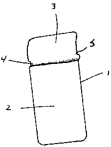
Fig. 1 is a front perspective view of the flashing apparatus;
Fig. 2 is a side view of the flashing apparatus of Fig. 1;
Figs. 3a-3e show a front perspective view of various flashing apparatuses that
incorporate aspects of the flashing apparatus into them;
to Fig. 4 is a front perspective view of the flashing apparatus in use with a
building
substrate and siding panels;
Fig. 5 is a side view of the flashing apparatus of Fig. I shown in use with a
building substrate and siding panels; and
Fig. 6a-6d shown a front perspective view of various flashing apparatuses.
DETAILED DESCRIPTION OF THE ILLUSTRATED EMBODIMENTS
Figs. 1-2 show the flashing apparatus 1. The flashing apparatus I itself
comprises
a largely planar main portion 2 and top portion 3 separated by a ridge 4
protruding from
its front face along its horizontal axis. The main body 2 has a height of
varying lengths,
depending on the size of siding panels 8 used, and a width sufficient for the
flashing
apparatus 1 to extend past the void between adjacent siding panels 8 as shown
in Fig. 4.
A leading edge 5 of the ridge 4 can be angled so that it is less than
perpendicular
to the main portion 2 and angled greater than perpendicular to the top portion
3. In this
Page 3
CA 02737540 2011-04-15
manner with the angle of the leading edge being less than perpendicular
relative to the
main portion 2, the user can slide the leading edge 5 and the ridge 4 of the
flashing
apparatus 1 underneath a siding panel (not shown) when the flashing apparatus
1 is being
installed.
In one aspect, the ridge 4 can be a semi circular protrusion extending
horizontally
across the flashing apparatus 1.
In one aspect, the top portion 3 can be slightly curved to aid a user in
sliding the
top portion 3 of the flashing apparatus I behind a siding panel (not shown).
Figs. 3a-3e show various alternate embodiments of the flashing apparatus 1
that
include a main body 12, 22, 32, 42 and 52 and a slightly curved top portion
13, 23, 33, 43
and 53 separated by ridges 14, 24, 34, 44 and 54 of differing shapes.
Fig. 3a illustrates a flashing apparatus 11 that has a ridge 14 defined by a
series of
spaced apart semi-circular protrusions 17 extending out of the main portion 12
of the
flashing apparatus 11. The protrusions 17 can be aligned to form a line
extending
substantially horizontally between the top portion 13 and the main body 12 of
the
flashing apparatus 11.
The leading edges 15 of the semi-circular protrusions 17 can be provided at an
angle to the top portion 13 greater than perpendicular and an angle greater
than
perpendicular from the main portion 12 so that the leading edge 15 is angled
away from
the top portion 13 of the flashing apparatus 11.
Fig. 3b illustrates a flashing apparatus 21 that has a ridge 24 extending
substantially horizontally between the top portion 23 and the main portion 22.
The ridge
24 can have a leading edge 25 that is angled away from the top portion 23 and
at an angle
that is less than perpendicular to the main portion 22. A trailing edge 26 can
also be
Page 4
CA 02737540 2011-04-15
provided connected to the leading edge 25 that is provided at a perpendicular
angle to the
main portion 25 or at an angle closer to perpendicular than the angle of the
leading edge
25.
Fig. 3c illustrates a flashing apparatus 31 that has a ridge 34 extending
substantially horizontally between the top portion 33 and the main portion 32.
The ridge
34 can have a leading edge 35 that is angled away from the top portion 33 and
at an angle
that is less than perpendicular to the main portion 32. A trailing edge 36 can
also be
provided at a perpendicular angle that is greater than perpendicular relative
to the main
portion 35. A joining portion 37 can be provided between the leading edge 35
and the
trailing edge 36.
Fig. 3d shows a variation of a flashing apparatus 41 wherein a main body 42
has a
ridge 48 down its length which may fit along the butt end joint of siding
panels 9. The
flashing apparatus 1 is preferably produced in a variety of weather-resistant
materials.
Fig. 3e shows a variation of a flashing apparatus 51 wherein there a number of
ridges 54 in the form of mechanical flaps. The ridges 54 separate a top
portion 53 from a
main body 52 of the flashing apparatus 51. These ridges 54 can be punched out
of the
main body 52 of the flashing apparatus 51 or attached to the main body 52. A
leading
edge 55 of the ridge 54 can be angled with angle less than perpendicular
relative to the
main body 52.
Figs. 4-5 show the flashing apparatus I in use. Although flashing apparatus I
is
shown in Figs. 4-5, a person skilled in the art will appreciate that flashing
apparatuses 11,
21, 31 and 41 could also be used. A structure's outer wall substrate 106,
which can
comprise various materials, is shown with an interior surface 107 and exterior
surface
108. Over the exterior surface 108 of the outer wall substrate 106, a
plurality of siding
panels 109 are attached. Each panel 109 has a length greater than its width,
and both
Page 5
CA 02737540 2011-04-15
dimensions may vary according to the panel's use. Each panel 109 has a top
edge 110, a
bottom edge 111, an interior face 112 and an exterior face 113.
The siding panels 109 are normally attached to the exterior surface 108 of the
building substrate 106 with fasteners 114 in horizontal rows, stacked
vertically. The
siding panels are normally attached with the top edge 110 of the siding panel
109 against
the exterior surface 108 of the structure and the bottom edge 111 of the
siding panel 109
overlapping the top edge 110 of the siding panel 109 that is below the first
panel 109.
This orientation, as depicted in Figs. 4-5, ensures that precipitation or
objects running
down the exterior face 113 of the siding panels 109 cannot penetrate behind
the siding
panels 109.
Siding panels 109 which do not span the entire length of the exterior of a
structure
must be placed against adjacent siding panels 109. This results in a void, or
butt end
joint, between adjacent siding panels 109 through which objects or
precipitation can
penetrate.
As shown in Figs. 4-5, when a flashing apparatus 1 is used under a butt end
joint
between adjacent siding panels 10 9, the top edge 110 of the siding panel 109
holds the
flashing apparatus I against the exterior surface 108 of the building
substrate 106, with
the ridge 4 of the flashing apparatus I in contact with the top edge 110 of
the siding panel
109. The top portion 3 of the flashing apparatus 1 extends up against the
exterior surface
108 of the building substrate 106. The main portion 2 of the flashing
apparatus 1 is held
against the interior face 12 of the siding pane 10 9. The said main portion 2
is of such a
length as to overlap onto the exterior face 113 of the siding panel 109
attached below the
first siding panel 109. In this manner, the main portion 2 of the flashing
apparatus 1
beneath butt end joints provides protection to the underlying building
substrate 106 from
weather and precipitation infiltration. The ridge 4 of the flashing apparatus
I acts to
support the flashing apparatus 1 in place relative to the siding panels 109
and provides a
Page 6
CA 02737540 2011-04-15
further barrier to weather and precipitation infiltration that may be forced
under siding
panels 109.
In one aspect, the flashing apparatus 1 can be affixed to the exterior surface
108
of the building substrate 106 prior to the permanent attachment of the siding
panels 109
to the building substrate 106 with fasteners 114.
In another aspect, the flashing apparatus 1 can be added beneath butt end
joints of
siding panels 109 after the loose attachment of the siding panels 109 to the
building
substratel0 6. The flashing apparatus I may be slid up behind siding panels
109, with the
top portion 3 as the leading edge. If the top portion 3 is slightly curved,
the leading edge
of the top portion 3 can be inserted under a bottom edge 111 of the siding
panel 109
while the main portion 2 of the flashing apparatus 1 is held an angle from the
exterior
surface 108 of the building substrate 106.
The top portion 3 can then be pushed under the siding panel 109 until the
ridge 4
reaches the bottom edge 111 of the siding panel 109. With the leading edge 5
of the
ridge 4 being angled away from the top portion 3 and at an angle less then
perpendicular
relative to the main portion 2, the ridge 4 can then be pushed under the
siding panel 109.
The ridge 4 can be forced under the siding panel 9 until it reaches top edage
110 of the
siding panel 109, at which point, the ridge 4 can be brought to rest in
contact with the top
edge 110 of the siding panel 109. The top edge 110 of the siding panel 109 can
hold the
flashing apparatus I up and in place against the exterior surface 108 of the
building
substrate 106 prior to the flashing apparatus I and the siding panels 109
being
permanently fastened to the building substrate 106 with fasteners 114.
Figs. 6a-6d illustrate flashing apparatuses 210, 220, 230 and 240 that include
one
or more vertical or diagonal ridges.
Page 7
CA 02737540 2011-04-15
Fig. 6a illustrates a flashing apparatus 210 that has a horizontal ridge 215
running
vertically along a body 212 of the flashing apparatus 210. The horizontal
ridge 215 can
be used to be inserted in between two abutting siding panels (not shown).
Fig. 6b illustrates another flashing apparatus 220 that has two horizontal
ridges
215 running vertically along a body 222 of the flashing apparatus 220.
Protrusions 217
allow the flashing apparatus 220 to be adjusted behind siding panels. The
ridges 215 are
positioned to be installed beneath edges of siding panels (not shown). These
ridges 215
can prevent water (such as blowing rain) from penetrating far beneath the
siding panels.
Additionally, the ridges 215 can be used to allow the positioning of the
siding panels to
be adjusted slightly, such as allowing an installer to adjust two abutting
siding panels so
that they lie substantially flush with one another.
Fig. 6c illustrates another flashing apparatus 230 having a generally
horizontally
positioned ridge 234 and a number of generally vertical ridges 235A, 235B. The
vertical
ridges 235A are provided proximate side edges of the flashing apparatus 220 on
a top
portion 233 of the flashing apparatus 230 and the vertical ridges 235B are
provided
proximate side edges of the flashing apparatus 220 on a main body 232 of the
flashing
apparatus 230.
Fig. 6d illustrates another flashing apparatus 240 having a series of
horizontal
ridges 246 protruding from the surface of a main body 242 of the flashing
apparatus 240
to channel water away from the edges of the flashing apparatus 240 to try and
prevent
water from penetrating beneath siding panels (not shown) installed over top of
the
flashing apparatus 240.
The foregoing is considered as illustrative only of the principles of the
invention.
Further, since numerous changes and modifications will readily occur to those
skilled in
the art, it is not desired to limit the invention to the exact construction
and operation
shown and described, and accordingly, all such suitable changes or
modifications in
Page 8
CA 02737540 2011-04-15
structure or operation which may be resorted to are intended to fall within
the scope of
the claimed invention.
Page 9