Note: Descriptions are shown in the official language in which they were submitted.
CA 2737715 2017-05-15
HYBRID SCAFFOLD SYSTEM
FIELD OF THE INVENTION
This invention relates to modular scaffolding systems that are erected as
impermanent
structures to support platforms. Scaffolding is used, inter alia, in the
industrial, commercial,
petro-chemical, power source, general industry and residential construction
markets.
BACKGROUND
Tube and coupler scaffolds are so-named because they are built from tubing
connected
by coupling devices. Due to their strength, they are frequently used where
heavy loads need to
be carried, or where multiple platforms must reach several stories high.
Components of
scaffolds include vertical standards having coupling rings or rosettes,
horizontal components
such as ledgers and guardrails coupled to the coupling rings or rosettes,
footings,
decks/platforms and diagonal braces. Their versatility, which enables them to
be assembled in
multiple directions in a variety of settings, also makes them difficult to
build correctly.
Figure 1 is an illustration of a vertical standard 100. Vertical standards are
typically
cylindrical tubes 101 comprised of hot-dip galvanized steel or aluminum. A
collar with an
expanded or reduced diameter or a spigot at either or both ends of the
vertical standard
facilitates the joining of vertical standards from end to end. Rosettes 102
are positioned and
then welded or otherwise attached along the tubes providing connections for
horizontal
members and diagonal braces. The vertical standard 100 can have from one to 8
or more
rosettes placed along the tubing using a predetermined spacing between
rosettes, for example,
about every 20 inches.
A conventional rosette 200, as seen in Figure 2, has a central aperture 203 to
receive
the vertical tubing of the vertical standard, four small openings 201A-D to
facilitate
right-angled connections of conventional ledgers and four larger openings 202
A-D to facilitate
connections at any angles of conventional ledgers. A conventional ledger has a
head 204
1
CA 2737715 2017-05-15
affixed thereto with a vertical slot and horizontal slot arranged therein.
Said head 204 is
positioned with respect to the rosette 200 such that the horizontal slot of
the head 204 is
positioned over and under the rosette 200 and the vertical slot of the head is
aligned with an
aperture of the rosette 200. A loose wedge 205 is then hammered into the
vertical slot (or gap)
to couple the ledger via the head 204 to the vertical standard via the rosette
200 using, inter
alia, frictional force. The conventional rosette is not configured to accept
both a swing arm
and ledger.
Disadvantageously, until the wedge 205 is installed there is significant play
between
the rosette 200 and head of a horizontal member giving rise to safety
concerns. Furthermore,
once installed, wedges often work free when workers traverse the platform.
When these
wedges work free, the scaffold can become unstable and collapse. Further, even
if the scaffold
does not collapse, steel wedges, which as seen in the Figure are not
integrated into the head or
the ledger, can fall from the scaffold injuring workers below.
What is desired is a hybrid scaffold system that overcomes the disadvantages
of the
conventional scaffold system.
SUMMARY
The invention comprises a hybrid scaffold system that overcomes the safety and
flexibility issues inherent in conventional scaffold systems. The ring,
collar, rosette or
component with similar functionality, is referred to as a rosette with respect
to the invention;
the vertical standard or component with similar functionality, is referred to
as a vertical
member with respect to the invention and the ledger, guardrail or component
with similar
functionality is referred to as a horizontal member. The use of the foregoing
terms is not to
be interpreted as limiting the scope of the invention.
More specifically, the invention comprises a swing head assembly comprising a
swing
head and pin, the swing head assembly being coupled to the first end of a
first horizontal
member. Another aspect of the invention is a swing head assembly at the first
end and second
end of the first horizontal member. Thc invention further includes a vertical
member made of
vertical tubing, including at least one rosette positioned thereon in coaxial
alignment with the
2
CA 2737715 2017-05-15
=
vertical tubing, the rosette having radially arranged cut-outs or apertures
for receiving at least
one swing head assembly. The swing head assembly is rotatably coupled to the
rosette at a
revolution joint.
The invention further comprises the above described first horizontal member
having
integrated therein at least one swing head assembly at a first end thereof, in
combination with
a second horizontal member having an internal wedge assembly therein. The
radially arranged
cut-outs or apertures of a rosette are dimensioned to accept the swing head
assembly and also
the mating elements, or prongs, of a head coupled to a horizontal member
having an internal
wedge assembly (internal wedge head). The internal wedge assembly has a rod
with a wedge
portion at a first end thereof, the rod being coupled at a second end thereof
to an internal
crank/cam assembly. An external handle is coupled to a crank/cam axle of the
internal
crank/cam assembly. The internal wedge head has a bore through the body
thereof, which the
wedge portion wholly or partially extends to lock the internal wedge head to
the rosette and
wholly or partially retracts to unlock the internal wedge head from the
rosette.
Further embodiments include a horizontal member with a swing head assembly at
each
end, alone and in combination with a rosette, and further in combination with
a horizontal
member with an internal wedge assembly and internal wedge head.
To those skilled in the art to which this invention relates, many changes in
construction
and widely differing embodiments and applications of the invention will
suggest themselves
without departing from the scope of the invention as defined herein and in the
appended claims.
The disclosures and the descriptions herein are purely illustrative and are
not intended to be in
any sense limiting.
DESCRIPTION OF THE DRAWINGS
A more complete understanding of the invention may be obtained by reference to
the
following Detailed Description, when taken in conjunction with the
accompanying Drawings,
wherein:
Figure 1 illustrates a vertical standard;
3
CA 2737715 2017-05-15
Figure 2 illustrates a rosette and conventional head and wedge;
Figure 3 is one embodiment of a rosette of the invention;
Figure 4 is onc cmbodiment of a swing head of the invention;
Figure 5 is a first view of one embodiment of a swing head assembly of the
invention;
Figure 6 is a second view of one embodiment of a swing head assembly of the
invention;
Figure 7 is a view of one embodiment of a swing arm (swing head assembly
coupled
to a horizontal member, without the pin) of the invention;
Figure 8 is a perspective view of the swing arm (swing head assembly on a
horizontal
member) coupled in a first position to a rosette;
Figure 9 is a perspective view of thc swing arm coupled in a second position
to a rosette;
Figure 10 is a view of two swing arms in a first position coupled to a
scaffold;
Figure 11 is a view of two swing arms in a second position coupled to a
scaffold;
Figure 12 is a view of a cubic arrangement of vertical members and horizontal
members
of the invention;
Figure 13 is a view of a scaffold of the invention wherein a first scaffold
portion is
suspended from a second scaffold portion, the suspended portion having been
erected using
swing arms; and
Figure 14 is a view of a rosette of thc invention with a swing head assembly,
an internal
wedge head and a conventional head and wedge arrangement coupled thereto.
DETAILED DESCRIPTION
The invention comprises a hybrid scaffold system that overcomes the safety and
flexibility issues inherent in conventional scaffold systems. The ring,
collar, rosette or
component with similar functionality, is referred to as a rosette with respect
to the invention;
the vertical standard or component with similar functionality, is referred to
as a vertical
member with respect to the invention and the ledger, guardrail or component
with similar
functionality is referred to as a horizontal member. The use of the foregoing
terms is not to
be interpreted as limiting the scope of the invention.
4
CA 2737715 2017-05-15
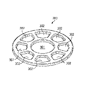
Referring now to Figure 3, the top view of one embodiment of a rosette 300 of
the
invention is shown. The embodiment of rosette 300 is circular in shape and has
a thickness to
it. Rosette 300 has a central aperture 301 or cut-out in a circular shape
dimensioned to receive
the vertical tubing of the vertical member. Once placed on the vertical
tubing, rosette 300 can
thus be welded or otherwise attached in a co-axial alignment with the vertical
tubing of the
vertical member. A plurality of rosettes can thus be positioned and affixed
along the length of
the vertical tubing. Between the outer circumference of rosette 300 and the
outer
circumference of the central aperture 301 are a plurality of radially arranged
cut-outs 302 for
receiving (i) the pin of a swing head assembly and/or (ii) prongs of at least
one internal wedge
head as further described herein. The grid arrangement of the radially
arranged cut-outs 302
allow for the flexible configuration or arrangement of swing arms and/or
horizontal members
to the vertical member via rosette 300. Figure 3 illustrates eight (8)
radially arranged cut-outs
302, although a different number of radially arranged cut-outs 302 can be
arranged on rosette
300. In an embodiment of the invention, the radially arranged cut-outs 302
generally comprise
trapezoids with inner and outer edges having circular arcs of concentric
circles of different
radii. The intersections of the line segments and arcs can be filleted,
comprising a concave
easing of the interior corners to reduce stress concentration. On a portion
of, and further cut
out from, the inner and outer edges of such trapezoids are arc shaped notches
comprising a
portion of a circle centered on the trapezoid. The edges of intersection of
each of the upper
and lower surfaces of the rosette with the vertical, interior walls of the
rosette can be rounded,
beveled or chamfered. The radially arranged cut-outs 302 are dimensioned to
receive (i) a pin
of a swing head assembly and/or (ii) descending, vertical prongs of the
internal wedge head.
Figure 4 illustrates a swing head 400 of the invention, said swing head having
bifurcated extensions and a connecting member, the bifurcated extensions being
an upper
extension 401 and a lower extension 402. Each of the upper extension 401 and
the lower
extension 402 have a flat, top surface, a left side, a flat, bottom surface, a
right side, a front
side (substantially a space curve or curved wall) and a back side dimensioned
to receive, or to
be received by a horizontal member, and edges between respective surfaces and
sides. Each
of the upper extension 401 and lower extension 402 are substantially the same
shape and
5
CA 2737715 2017-05-15
dimension, each being similar to a rectangular prism with the front sides
thereof being rounded
providing a front side in the form of a curved wall or space curve.
With respect to upper extension 401, the flat planes of the top surface and
bottom
surface are parallel. The planes of the left side and right side, except where
the curvature of the
front side commences, are substantially parallel. The planes of the top
surface and bottom
surface are orthogonal to the left side and right side.
With respect to lower extension 402, the flat planes of the top surface and
bottom
surface are parallel. The planes of the left side and right side, except where
the curvature of the
front side commences, are substantially parallel. The planes of the top
surface and bottom
surface are orthogonal to the left side and right side.
With respect to the orientation of the extensions as described herein, the
bottom surface
of upper extension 401 is apositioned the bottom surface of lower extension
402.
The upper extension 401 and lower extension 402 are connected with a
connecting
member 405 sandwiched between their respective bottom surfaces proximate the
back sides
thereof. The connecting member 405 serves as a further connection to a
horizontal member.
A front end of upper extension 401 is proximate the front side of the upper
extension
401. Proximate the front end of the upper extension 401 is upper extension
bore 404 which
passes through the top surface, upper extension body and bottom surface. A
front end of lower
extension 402 is proximate the front side of the lower extension 402.
Proximate the front end
of the lower extension 402 is lower extension bore 403 which passes through
the top surface,
lower extension body and bottom surface.
Figure 5 is a first view of one embodiment of a swing head assembly of the
invention
showing the swing head 400 comprised of upper extension 401, lower extension
402 and upper
extension bore 404. Also shown in Figure 5 is pin 501 which is dimensioned to
fit within
upper extension bore 404, then one of the radially arranged cut-outs 302 of
rosette 300 and
then lower extension bore 403. Pin 501 further has a pin bore positioned
orthogonal to the
central axis through the cylindrically shaped pin 501, through which a pin
stop 502 comprising
a dowel, pin, elevis or component with similar functionality is inserted, the
ends of which,
when viewed from the top thereof, extend beyond the circumference of pin 501
and serve to
retain pin 501 in the upper extension bore 404, radially arranged cut-out 302
of rosette 300 and
6
CA 2737715 2017-05-15
lower extension bore 403. Alternatively, an end cap or other stopping means
can be affixed to
an end of pin 501 to retain pin 501 in the swing head. When pin 501 is
installed as described,
it provides a rotation joint between the rosette and horizontal member
allowing swing head
(and hence, a horizontal member coupled thereto) to swing, swivel or rotate in
the plane of the
surface of rosette 300, which plane of rotation is orthogonal to the vertical
member to which
the rosette is affixed.
Figure 6 is a side view of one embodiment of a swing head assembly of the
invention
showing swing head 400 and pin 501 and connecting member 405. Figure 7 is a
view of one
embodiment of a swing arm 700, comprising swing head 400 coupled to horizontal
member
701. As seen therein, connecting member 405 is dimensioned to fit within the
end of the tubing
of an end of horizontal member 701.
Figure 8 is a perspective view of the swing arm 700 with the attached swing
head
assembly which further comprises swing head 400 and pin 501 affixed to
horizontal member
701 coupled in a first position to a rosette. Figure 9 is a perspective view
of swing arm 700
with the attached swing head assembly which further comprises swing head 400
and pin 501
affixed to horizontal member 701 rotated into a second position to a rosette
from the position
seen in Figure 8.
Figure 10 is a view of two swing arms 1001, 1002 in a first position coupled
to a
scaffold 1000. As seen therein, each of the swing arms have, at each
respective end thereof, a
swing head assembly. Figure 11 is a view of the two swing arms 1001, 1002 of
Figure 10 in a
second position coupled to scaffold 1000.
Figure 12 is a view of a scaffold 1200 in a cubic arrangement of vertical
members and
horizontal members using components of the invention. Figure 13 is a view of
scaffold 1300
having a first scaffold portion 1301 suspended from a second scaffold portion
1302, the
suspended portion having been erected using swing arms 700.
Figure 14 is a view of the rosette 300 of the invention showing coupled
thereto a swing
head assembly 400, an internal wedge head 1401 and a conventional head and
wedge
arrangement. The internal wedge head 1401 is coupled to a horizontal member
having an
internal wedge assembly. The radially arranged cut-outs or apertures of a
rosette 300 are able
to also receive mating elements, or prongs, of internal wedge head 1401. The
internal wedge
7
CA 2737715 2017-05-15
assembly has a rod with a wedge portion at a first end thereof, the rod being
coupled at a second
end thereof to an internal crank/cam assembly in the horizontal member. A
handle or crank is
coupled to a crank/cam axle of the internal crank/cam assembly, the internal
wedge head 1401
having at least one or a plurality of mating elements or prongs dimensioned to
fit within certain
of the cut-outs or grid of apertures formed in the rosette 300, the internal
wedge head 1401
having a bore through which the wedge portion wholly or partially extends out
of internal
wedge head 1401 to lock internal wedge head 1401 to the rosette 300 and wholly
or partially
retracts into internal wedge head 1401 to unlock internal wedge head 1401 from
the rosette
300.
The invention comprises a swing head assembly comprising a swing head and pin,
the
swing head assembly being coupled to at least the first end of a first
horizontal member.
Another aspect of the invention is a swing head assembly at the first end and
second end of the
first horizontal member. The invention further includes a vertical member made
of vertical
tubing, including at least one rosette positioned thereon in coaxial alignment
with the vertical
tubing, the rosette having radially arranged cut-outs or apertures for
receiving at least one
swing head assembly. The swing head assembly is rotatably coupled to the
rosette at a
revolution joint.
The invention further comprises the above described first horizontal member
having
integrated therein at least one swing head assembly at a first end thereof, in
combination with
a second horizontal member having, preferably, an internal wedge head at least
at one end
thereof. The radially arranged cut-outs or apertures of a rosette are able to
receive mating
elements, or prongs, of a horizontal member head, the horizontal member having
therein an
internal wedge assembly, the internal wedge assembly having a rod with a wedge
portion at a
first end thereof, the rod being coupled at a second end thereof to an
internal crank/cam
assembly. A crank or handle is coupled to a crank/cam axle of the internal
crank/cam assembly,
the horizontal member head having at least one or a plurality of mating
elements or prongs
dimensioned to fit within certain of the cut-outs or grid of apertures formed
in the rosette, the
internal wedge head having a bore through which the wedge portion wholly or
partially extends
out of the horizontal member head to lock the horizontal member head to the
rosette and wholly
or partially retracts into the horizontal member head to unlock the horizontal
member head
8
CA 2737715 2017-05-15
from the rosette. The horizontal member having an internal wedge assembly is
as described
in Applicant's U.S. Patent No. 8,393,439. As described therein, such
horizontal member
advantageously allows the user thereof to engage and disengage both wedges
coupling a
vertical member from a single location.
The invention, as structurally described, functionally allows one to use swing
or swing
arm horizontal members for cantilevered platforms which can be used, e.g., on
off-shore and
bridge platforms. The invention facilitates precision angles of horizontal
members thus saving
time when squaring the base or re-racking the scaffold. The invention
facilitates the raising of
platforms via swing stage motors or cranes. The invention is configured to
enable the erection
of suspended platforms in elevated situations.
The invention is seismic qualified due to its novel self-squaring rosette and
head
combination. The invention is a secondary positive locking design using
internal gussets and
360 degree connection rosette designs.
In operation, the invention provides strong, durable load bearing design for
light,
medium, and heavy duty load capacities. It can be used in flammable and
explosive
environments due to the nature of its rigid design. Its positive locking
design permits it to be
assembled in approximately half the time as a conventional scaffold.
The described embodiment of the invention shows a rosette that receives eight
horizontal members, but is not limited to such arrangement. The connection of
the heads and
rosette of the invention is designed to meet 100 A tie off requirements and
standards. The
swing arms of the invention allow the scaffold erector to construct almost any
shaped working
platform from the air. The swing arms collapse to the main scaffold allowing
the scaffold
erector to install all the structural components from an existing platform. In
the process, the
scaffold erector can utilize standard scaffold components such as clamps,
tubes, metal planks,
horizontal, and vertical scaffold members. After all the structural components
are installed, the
erector can swing the horizontal components out up to 180 degrees. Hence, in
one
embodiment, the platform can be cantilevered approximately (10) feet
unsupported. Once the
erector has the swing arms at a 90 degree position, he can utilize standard
scaffold components
such as metal planking and tubes and clamps to support and deck of the
invention. In this
manner, the erector can install an initial smaller platform then "leap-frog"
the platform while
9
CA 2737715 2017-05-15
still suspended. The erector also has the option to build a scaffold from the
ground or other
elevations then work the structure vertically and upward. A conventional
system us unable to
provide this flexibility as it must be suspended from structural steel or
elevated by swing stage
motors. In contrast, using the invention, the erector can build multiple
levels from the ground
up or suspend from steel if needed or even fly with swing stage motors.
The swing head and connected horizontal member of the invention facilitates
the
insertion of a lattice bolt/pin at each connection joint. The clevises shape
of the swing arm
assembly supports the base of the platform thus allowing it to be suspended
and elevated via
swing stage motors. This is an additional advantage of the invention over a
conventional
scaffold.
The invention advantageously permits an erector to suspend a platform in an
elevated
position. By installing the swing arms in their collapsed position it allows
the erector to install
additional platforms from a safe, stable location.
As noted herein, components of the invention include at least one horizontal
member
which horizontal member preferably has a swing head at each end thereof, at
least one vertical
member including at least one rosette coaxially positioned thereon, the
rosette having apertures
for receiving (i) a pin of the swing head assembly and/or (ii) mating elements
or prongs of an
internal wedge head coupled to a horizontal member with an internal wedge
assembly therein,
the internal wedge assembly having a first rod with a wedge portion at a first
end thereof, the
first rod being coupled at a second end thereof to an internal crank/cam
assembly, a crank or
handle coupled to a crank axle of the internal crank/cam assembly, the
internal wedge assembly
further having a second rod with a wedge portion at a first end thereof, the
second rod being
coupled at a second end thereof to the internal crank/cam assembly. The
internal wedge
assembly causes the wedge portion to be wholly or partially extendable and
retractable into the
internal wedge head and/or hollow tube of the horizontal member, wherein, when
the mating
elements of the horizontal member are received in the radially arranged cut-
outs of the rosette,
the internal wedge assembly, when actuated, causes the wedge portion to
rigidly join the
horizontal member to the rosette.
The invention has at least one rosette coaxially attached, via, e.g., a weld,
to each
vertical member, and a vertical member may have a plurality of evenly or
unevenly spaced
CA 2737715 2017-05-15
rosettes coaxially welded along a vertical member. The rosette has a pattern
or grid of apertures
designed to receive the mating elements, such as prongs at the end of a
horizontal member. A
head may be located at the end of the horizontal member. The horizontal member
is a hollow
tube, preferably cylindrical in shape, having a first end and a second end. At
the first end and
the second end may be fixedly attached, a swing head assembly or wedge head
assembly, as
more fully described herein.
The embodiments shown and described above are only exemplary. Even though
numerous characteristics and advantages of the preferred embodiment of the
invention have
been set forth in the foregoing description together with details of the
invention, the disclosure
is illustrative only and changes may be made within thc principles of the
invention to the full
extent indicated by the broad general meaning of the terms used herein. For
example, the
concepts described herein for coupling horizontal members to vertical members
can be adapted
to couple bracing members to vertical members or to horizontal members.
Coupling includes,
but is not limited to attaching, engaging, mounting, clamping, welding,
bolting and
components used for coupling include bolts and nuts, rivets, clevis, latches,
clamps, welds,
screw, rivet and the like. Further, a rosette having eight (8) radially
arranged cut-outs is
described herein for illustrative purposes and a rosette having more or less
radially arranged
cut-outs is considered to be within the scope of this invention. Also, the
invention describes a
rosette having a standard diameter of about seven (7) inches, however, any
suitable diameter
can be used. The rosette can include any suitable cut-out shape that is
dimensioned to receive
a corresponding pin of the swing head assembly. The vertical member can have
any number
of coaxially aligned rosettes attached thereto, the vertical spacing of such
rosettes being any
such distance as is suitable for the intended use.
11