Note: Descriptions are shown in the official language in which they were submitted.
CA 02737741 2011-03-17
WO 2010/036176 PCT/SE2009/000421
AIR CLEANING APPARATUS
Technical field of the invention
The present invention relates to an air cleaning
apparatus, in particular an apparatus for cleaning of room air,
here meaning air in residential spaces, offices or industrial
premises, but also for cleaning of outside air. More
specifically, the invention relates to an air cleaning
apparatus for cleaning of indoor air and/or outdoor air, which
apparatus comprises an air flow duct, with an extent in an
axial direction, to accommodate the air flow entering the
apparatus, an air-conveying fan unit disposed in the air flow
duct, a precipitator connected to a high-voltage source and
with a throughflow passage for air which is to be cleaned,
which precipitator comprises two electrode elements or two
groups of electrode elements, each of the respective two being
connected to a respective pole of the high-voltage source, and
a unipolar corona electrode disposed close to one end of the
air flow duct.
State of the art
There are known apparatuses in the form of two-stage
electric filters in which an ionisation device takes the form
of a corona electrode and a target electrode/counter electrode
which together constitute an ionisation chamber. The
ionisation chamber, which is often constituted by the walls of
the target electrode, delineates a well-defined space within
which the charging of the dust particles in the air takes place
in the more or less immediate vicinity of a separator which
forms part of the two-stage electric filter and which is often
referred to as a precipitator. The effectiveness of such air
cleaning devices, so-called two-stage filters, depends to a
very great extent on the effectiveness of the ionisation
chamber. One way of achieving effective charging of the
airborne dust is to drive the corona electrode with powerful
corona current, but this results also in an undesirable
powerful ozone emission. Certain manufacturers of two-stage
electric filters, e.g. Oreck in the U.S.A., use a special ozone
filter to deal with this problem.
CA 02737741 2011-03-17
WO 2010/036176 PCT/SE2009/000421
2
Another way of achieving effective charging but low
ozone emission, i.e. with low corona current, is to configure
the ionisation chamber in such a way that the charging space
delineated by the target electrode of the ionisation chamber,
through which space the airborne particles pass on their way to
the precipitator, is of great extent in the air flow direction.
The dwell time of the particles in this region thus becomes
relatively long, with the consequence that the time available
for the charging is also relatively long. US 5,993,521
indicates a two-stage electric filter in which this way of
achieving effective charging is implemented.
However, there are disadvantages of the ionisation chamber
configuration according to that patent, viz, the physical
volume of the ionisation chamber, which results in relatively
voluminous apparatuses. This is particularly sensitive in the
case of using high-resistance precipitators as described for
example in US 6,203,600, which afford the possibility of
configuring relatively large circular precipitators with a
diameter of up to 100 cm or more. A matching ionisation
chamber for such a circular precipitator is with advantage
tubular, with diameter and length, measured in the air flow
direction, corresponding to the diameter of the precipitator.
Over recent years the debate about indoor environments
and their impact on human health has increasingly focused on
the presence of particles in air inhaled. In this context
there has been a great increase in interest in so-called
freestanding air cleaners to complement traditional ventilation
systems. This entails exacting requirements for the ability of
the apparatuses to significantly reduce airborne pollution
without harmful generation of ozone and with low noise levels
and low energy consumption. There are also requirements with
regard to adapting the apparatuses to indoor environments,
including their size, suitable siting potential and, not least,
easy servicing.
US 6,398,852 presents a device of the kind indicated in
the introduction with the object, on the basis of preferred
embodiments, of reducing the dimensions of the air cleaning
apparatus in the air flow direction through the apparatus in
cases where circularly symmetrical precipitators configured in
CA 02737741 2011-03-17
WO 2010/036176 PCT/SE2009/000421
3
accordance with US 6,203,600 which maintain low ozone
generation are used. The effectiveness of the device does of
course depend on the air flow dwell time in the ionisation
chamber and on the corona current.
Another way of achieving effective charging of airborne
dust by means of a very low corona current is described in
US 5,980,614. According to that invention, a corona electrode
in the form of a unipolar ion source (brush/point) is disposed
close to a device which comprises a precipitator, a fan and a
high-voltage source, which corona electrode is so disposed that
the ions generated at it are substantially able to spread
freely from the corona electrode into the space which contains
the air mass which is to be cleaned. Thus the space in which
the device is situated constitutes a large ionisation chamber.
In relative terms, the dwell time for the particles is
therefore very long, which makes it possible to use an
extremely low corona current. The latter may be less than 1
microampere, which in comparative terms is a very low current.
That way of causing effective charging of aerosol particles by
extremely low corona discharge certainly works, but there are
disadvantages with such a solution. Not only may dirt
particles deposit themselves upon the walls of the room, but
persons who are in the vicinity of the device may also become
electrically charged, which is not inherently dangerous but may
be felt to be unpleasant.
In this context it is important to note that the
requirements for effective charging of particles for cleaning
by so-called two-stage electric filters are quite distinct from
the requirements for cleaning of particles in a room with so-
called ionisers. The effectiveness of particle charging for a
device with a fan and for a precipitator, i.e. the
effectiveness of a two-stage electric filter, needs to match
the velocity of the air flow through such a device, since
otherwise the air cleaning capacity will be low, as only
electrically charged particles (aerosols) can be separated in a
precipitator. Charging and cleaning of particles by means of
an ioniser, with or without a particle-attracting electrode
disposed at the ioniser casing, involve no such requirements.
Such devices are dimensioned so that the ion cloud from the
CA 02737741 2016-02-04
4
corona electrode may spread freely in the space in which the device is
situated.
Objects and features of the invention
A primary object of the present invention is to propose a two-stage electric
filter of the
kind defined in the introduction which achieves effective separation of
airborne dust (aerosols) by
using extremely low corona current, more specifically corresponding to the
levels of corona
current which are applicable in devices with unipolar corona electrodes
(brush/point) and free ion
migration in the room, see for example US 5,980,614.
A further object of the present invention is to minimise the extent of the
electric filter in
the air flow direction.
In accordance with one embodiment of the present invention there is provided
an air
cleaning apparatus for cleaning of indoor air/outdoor air, which apparatus
comprises an air flow
duct, with an extent in an axial direction, to accommodate air flow entering
the apparatus, an air-
conveying fan unit disposed in the air flow duct, a precipitator connected to
a high-voltage source
and with a through flow passage for air which is to be cleaned, which
precipitator comprises two
electrode elements or two groups of electrode elements, each of the respective
two being connected
to a respective pole of the high-voltage source and a unipolar corona
electrode disposed close to
one end of the air flow duct. A target electrode is disposed at radial spacing
from the corona
electrode. The corona electrode is disposed such that ions generated at it can
freely spread away
from the corona electrode towards the target electrode and that the target
electrode surrounds the
air flow entering the apparatus.
In a preferred embodiment of the invention, the corona electrode is disposed
centrally in
the air flow duct in a region at one end of the air flow duct and the target
electrode is disposed
close to the same end of the air flow duct. Preferably, the target electrode
is disposed at a constant
radial spacing from the corona electrode.
In accordance with another preferred embodiment of the present invention an
inlet
grille/coarse filter is disposed between the precipitator and the target
electrodes in the axial
direction of the air flow duct. The grille/coarse filter is made of an
electrically insulating material.
CA 02737741 2016-02-04
4a
Preferably, the corona electrode is electrically connected to one pole of the
high-voltage
source and the target electrode is connected to the other pole of the high-
voltage source. The
polarity of the corona electrode in relation to the earth potential is
opposite to the polarity of the
target electrode in relation to earth potential.
Preferably, the corona electrode and/or the target electrode is/are connected
to the high-
voltage source via high-resistance resisters with a resistance greater than 1
Gohm, more preferably
greater than 2 Gohm.
In a preferred embodiment, the cleaning apparatus comprises a permanent
portion and an
interchangeable portion where the permanent portion comprises the fan unit and
high-voltage unit
and the interchangeable portion comprises the precipitator, the corona
electrode and the target
electrode. In one embodiment, the permanent portion further comprises a base
element and the
base element and the interchangeable portion comprise cooperating engaging
means.
Brief description of the drawings
Preferred embodiments of the invention are described below with reference to
the attached
drawings, in which:
Fig. 1 depicts a schematic and partly sectional view of a first embodiment of
the electric
filter according to the present invention; and
Fig. 2 depicts a schematic exploded view of the constituent parts of an
alternative
embodiment of the electric filter according to the present invention.
Detailed description of preferred embodiments of the invention
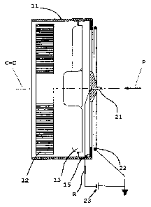
The air cleaning apparatus depicted in Fig. 1 takes the form of a two-stage
electric filter
which comprises a preferably circular cylindrical casing 11 which serves also
as air flow duct. The
axis C-C in Fig. 1 defines the axial direction of the electric filter and also
constitutes a centreline.
The electric filter comprises also a readily interchangeable and preferably
circular cylindrical
electrostatic precipitator 12 disposed in the casing 11, and an air-conveying
device in the form of
a fan/fan unit 13 which
CA 02737741 2011-03-17
WO 2010/036176 PCT/SE2009/000421
serves to convey air through the device. The precipitator 12
is configured in accordance with the description in
US 6,203,600 whereby the precipitator 12 is cylindrical and
made of high-resistance material. US 6,203,600 describes also
5 how a precipitator of the relevant kind is connected to a high-
voltage source, and that specification is therefore to be
referred to as regards the connection of the precipitator 12 to
a high-voltage source 23 which is described below.
The electric filter comprises also an inlet grille 15 so
configured that it acts like a coarse mechanical filter, i.e.
large particles in the air will be caught in the inlet grille
15. The inlet grille 15 is made of insulating material,
preferably plastic, and is pervious to air flow.
A unipolar corona electrode 21 with axial extent is
disposed in the form of a carbon fibre brush in the centre of
the portion of the inlet grille 15 which is pervious to air
flow. A circular counter electrode/target electrode 22 which
is symmetrical with respect to the corona electrode 21 is
disposed in the form of a ring in the region of the periphery
of the inlet grille 15 and at radial spacing from the corona
electrode 21. Fig. 1 depicts schematically how the corona
electrode 21 is connected to a negative first pole of a high-
voltage source 23 and the target electrode 22 is connected to a
second pole of the high-voltage source 23, which second pole is
electrically earthed.
The air flow generated by the fan 13, represented by the
arrow P in Fig. 1, thus passes through the inlet grille 15 of
the electric filter, past the fan 13 and through the
precipitator 12.
Laboratory tests have shown that even an extremely small
corona current, less than 1 microampere, is sufficient to
achieve effective charging of the particles (aerosols), i.e.
for achieving high separation of them in the downstream
precipitator 12. What is surprising with this arrangement is
that a majority of the corona current (in the form of an ion
cloud) generated at the corona electrode 21 reaches the target
electrode 22 instead of, as in the case of the device according
to US 5,980,614, migrating into the room in which the device is
situated. As the magnitude of the corona current (a fraction
CA 02737741 2011-03-17
WO 2010/036176 PCT/SE2009/000421
6
of a microampere) corresponds to the values in accordance with
US 5,980,614, this means that it is still perfectly sufficient
to ensure that charging of particles takes place in the
vicinity of the inlet area of the device and that free
migration of ions into the space in accordance with US
5,980,614 has substantially no appreciable effect on the
charging of particles.
The very high separation effectiveness in combination
with extremely low corona current indicates a certain expansion
of the ion cloud from the corona electrode 21, away from the
inlet area of the electric filter, i.e. in a direction opposite
to the air flow, so that particles in the air flow which pass
the inlet to the electric filter have sufficient dwell time to
acquire an electrical charge. Laboratory tests have shown that
a majority of the expansion of the ion cloud between the corona
electrode 21 and the target electrode 22 takes place
perpendicularly out from the plane which the target electrode
22 defines and in the opposite direction to the air flow
direction P. The expansion of the ion cloud in the opposite
direction to the air flow direction P reaches at most a
distance corresponding to the radial spacing between the corona
electrode 21 and the target electrode 22. The expansion of the
ion cloud from the corona electrode 21 will also be easy to
regulate by selecting the voltage of the target electrode 22.
If the target electrode 22 is connected to a pole of the
high-voltage source whose polarity in relation to earth
potential is opposite to the voltage of the corona electrode,
the expansion of the ion cloud from the corona electrode 21 to
the target electrode 22 is reduced. The reason is that upon
such energisation of the electrodes 21 and 22 in combination
with the extremely low corona current, the surfaces of the room
will act as electrostatic shield electrodes or reflector
electrodes, i.e. the ion cloud generated between the corona
electrode 21 and the target electrode 22 will be prevented, by
the room's electrical status relative to the target electrode
22, from migrating to the surfaces of the room. The expansion
of the ion cloud from the corona electrode 21 can therefore be
regulated, as also the dwell time for the passage of the air
flow through the ion cloud.
CA 02737741 2011-03-17
WO 2010/036176 PCT/SE2009/000421
7
The ever-increasing requirements for low or negligible
ozone generation and hence exceptionally low levels of corona
current have the effect that the electrostatic field between
the corona electrode 21 and the target electrode 22 should not
be disturbed by other conductive and energised parts of the
device which might draw to themselves part of the corona
current and hence increase ozone generation. Such parts may
include the precipitator 12, particularly if it is situated
upstream of the fan 13 and therefore nearest to the corona
electrode 21. The blades of the fan 13, its motor and its
frame are also such parts if they are made of conductive
material. To prevent this phenomenon, the blades and any frame
of the fan 13 depicted by way of example in Fig. I are made of
plastic.
If the precipitator 12 is situated near to the inlet
aperture of the electric filter, the precipitator 12 may be
protected from receiving part of the corona current by, for
example, a surface of electrically insulating material of foam
plastic type or the like, which surface may have air flowing
through it.
In the embodiment depicted in Fig. 1, the target
electrode 22 takes the form of a wire ring disposed close to
the inlet grille 15. Other embodiments of the target electrode
may of course be used, e.g. they may have a certain extent in
the air flow direction or in a radial direction. It is
important, however, that the target electrode 22 should
substantially enclose/surround the whole of the air flow which
is intended to be cleaned and that the target electrode 22,
given the location and energisation of the corona electrode 21,
is in terms of field (electrostatic field) substantially
circular and symmetrical relative to the corona electrode 21.
This means that the ion cloud generated will be similar, as
viewed radially from the location of the corona electrode 21.
As regards target electrodes 22 with a large diameter
that are adapted to applying voltages distinct from nil, it may
be practical to divide the target electrode 22 into a plurality
of parts electrically insulated from one another and each
connected to the high-voltage source via separate high-
resistance resistors. This will reduce the capacitive energy
CA 02737741 2011-03-17
WO 2010/036176 PCT/SE2009/000421
8
stored in the target electrode 22 and hence also the discharge
energy arising upon a possible short-circuit or touch. For
these reasons, the target electrode 22 in accordance with the
invention may with advantage be made of dissipative or semi-
conductive material or be provided with a coating of
dissipative or semi-conductive material.
The present invention is not limited to circular
precipitators. Other shapes of precipitator may be used, but
what is essential is that the electrostatic field round the
corona electrode 21 is circularly symmetrical, which can most
easily be achieved with a unipolar corona electrode 21 and a
circularly symmetrical target electrode 22, and that the ion
cloud generated round the corona electrode 21 can freely fill
the space in the vicinity of the electric filter's inlet area.
The two-stage electric filter according to the invention whose
characteristics are indicated in the claims thus has both an
ionisation electrode/corona electrode 21 and a target electrode
22, which components may together be regarded as constituting
an ionisation chamber without any physical limitation in the
counterflow direction. In other words, the physical dimensions
of the electric filter's ionisation chamber are many times
greater than the "disc-like" ionisation chamber defined by the
circular target electrode 22 and the corona electrode 21.
It should be noted that the electric filter also works
in cases where the expansion of the ion cloud to some extent
fails to reach the target electrode 22 but instead reaches
other conductive and energised parts of the electric filter.
However, this will be at the cost of a higher corona current,
i.e. greater ozone emission without improving the electric
filter's efficiency, i.e. its particle separation
effectiveness.
The inlet grille 15 depicted in Fig. 1 is not a
necessary part of this invention. The unipolar corona
electrode 21 may be situated substantially in the symmetry axis
of the target electrode 22 at the inlet to the air flow duct
and followed, as viewed in the air flow direction through the
duct, of for example the precipitator 12. It is essential that
the corona electrode 21 is axially directed and points in the
opposite direction to air flow through the duct, i.e. towards
CA 02737741 2011-03-17
WO 2010/036176 PCT/SE2009/000421
9
the surroundings. If the inlet grille 15 is dispensed with, it
is important that precipitator 12 is screened relative to the
corona electrode 21, e.g. by an electrically insulated surface
between the corona electrode 21 and the precipitator 12.
Laboratory tests have shown that it is the portion of
the target electrode 22 situated nearest to the corona
electrode 21 which receives the most corona current. The
particular shape of the target electrode 22 is therefore of
minor significance if it comprises not only the circularly
symmetrical portion facing towards the corona electrode 21 but
also other portions which extend further away from the corona
electrode 21.
It is of course not necessary to use a carbon fibre
brush 21 as corona electrode. A point or some other known form
of unipolar short corona may also be used. Opposite polarity,
i.e. positive corona and negative voltage on the target
electrode 22, may also be applicable.
The open ionisation chamber and the expansion of the ion
cloud towards the target electrode 22 create, as viewed from
the corona electrode 21 towards the target electrode 22, a
nearly hemispherical region (dwell space) in which there is
risk of electrostatic charging. This is not dangerous but may
be felt to be unpleasant. The present invention makes it
possible to significantly minimise this risk. This possibility
is surprisingly afforded by the extremely low corona current.
This is achieved by extremely high resistances R situated
between the poles of the high-voltage source and the connection
to the corona electrode 21 and/or the target electrode 22. In
Fig. 1, only one resistor R is placed between the high-voltage
source H and the corona electrode 21.
Laboratory tests have shown that a significant effect
can be achieved at even only about 1 Gohm resistance R, but the
resistance value may preferably be greater than 2 Gohm. The
greater the resistance value, the longer the time for which any
part of the body, e.g. hands, may remain in the vicinity of the
corona electrode 21 without risk of electrostatic charging.
This is extremely important from a comfort point of view and
only possible in practice at corona currents representing a
fraction of a microampere. By way of example it may be
CA 02737741 2011-03-17
WO 2010/036176 PCT/SE2009/000421
mentioned that a corona current of 0.1 microampere x 10 Gohm
resistance results in a voltage drop of only 1 kV, as against
an approximately 7-8 kV voltage drop between the corona
electrode 21 and the target electrode 22 if they are situated
5 at a mutual radial spacing of 15 cm. In other words, the
voltage increase across the protective resistor (10 Gohm) which
has to be taken into account in designing the high-voltage unit
for the purpose is only about 10% of the respective voltage
drop across the protective resistor. Should the corona current
10 necessary for sufficient particle charging be of the order of 3
microamperes, which is also extremely small in the context, the
voltage drop across the protective resistor R will represent 30
kV, which would be unreasonably large with respect to
production cost and other electrical operating parameters.
The alternative embodiment depicted in Fig. 2 of an air
cleaning apparatus according to the present invention comprises
a preferably circular cylindrical casing 111, the axial
direction of which is denoted by the axis C-C, which axis
constitutes also the centreline of the casing 111. The casing
111 serves as air flow duct. The casing 111 accommodates a
precipitator 112 configured in accordance with the description
in US 6,203,600, whereby the precipitator 112 is cylindrical
and made of high-resistance material. A unipolar corona
electrode 121 is integrated in the precipitator 112, takes the
form of a brush and is situated at the centre of the
precipitator 112. The corona electrode 121 has an extent in a
direction opposite to the air flow direction through the air
cleaning apparatus, which air flow direction is designated P in
Fig. 2.
The casing 111 also accommodates a target electrode 122
in the form of a ring fitted in an air intake aperture of the
casing 111.
An inlet grille/coarse mechanical filter 115 made of
electrically insulating material is disposed between the target
electrode 122 and the precipitator 112 as viewed in the axial
direction C-C of the casing 111. The inlet grille/coarse
filter 115 has a cylindrical circumference for adaptation to
the precipitator 112 and the target electrode 122.
CA 02737741 2011-03-17
WO 2010/036176 PCT/SE2009/000421
11
The diameters of the precipitator 112, the coarse filter
115 and the target electrode 122 are of the same order of
magnitude. In the region of the end of the casing 111 which
faces away from the target electrode 122, the casing 111 is
provided with apertures 130 whose function is explained below.
The casing 111 and its components 112, 115, 121, 122 are
intended for once-only use, i.e. the unit constituted by the
casing 111 and its components 112, 115, 121, 122 is replaced
when the user finds cause for doing so, e.g. when any of the
components is so contaminated that cleaning is no longer
considered sensible.
The air cleaning apparatus according to the alternative
embodiment also comprises a permanent portion comprising a base
element 131 with hooklike engaging means 132 which are adapted
to cooperating with the apertures 130, i.e. the hooklike
engaging means 132 and the apertures 130 constitute a
releasable connection between the casing 111 and the base
element 131. The centreline C-C constitutes also a centreline
for the permanent portion and defines also the permanent
portion's axial direction.
The permanent portion comprises a fan unit 113 recessed
in the base element 131, i.e. the fan unit 113 is countersunk
to a certain extent in the base element 131, in its axial
direction C-C. The fan unit 113 comprises a fan blade 133
surrounded by a protective cage 134 which forms part of the fan
unit 113. The fan unit 113 comprises also an electrical
component 135 comprising a power source for the fan, and a
high-voltage unit which generates the corona current between
the corona electrode 121 and the target electrode. The high-
voltage unit is connected to the corona electrode 121 and the
target electrode 122 when the base element 131 of the permanent
portion is assembled with the casing 111.
With regard to the materials of the various parts, we
refer to what was stated above with regard to each of those
parts. Also with regard to the ionisation of the incoming air,
symbolised by the arrow P in Fig. 2, we refer to what was
stated above with regard to corona current and to expansion of
the ion clouds formed during the ionisation.