Note: Descriptions are shown in the official language in which they were submitted.
CA 02737965 2011-03-21
WO 2010/043038
PCT/CA2009/001462
Apparatus and Method for Controlling Variable
Power Conditions in a Fuel Cell
Field of the Invention
This invention relates generally to the field of fuel cells, and in particular
to an apparatus
and a method for controlling variable power conditions in a fuel cell.
Background of the Invention
The advancement of portable electronics and the continual integration of
functionality
into a single all-encompassing device has created an increased demand on
energy
supply. The incumbent Li ion battery is not projected to sufficiently
accommodate this
growing demand. An attractive alternative for devices operating in the < 100 W
range is
the direct methanol fuel cell (DMFC). The DMFC could potentially bridge the
gap in
performance, as methanol has a high energy density (4820 Wh L-1), can be
continuously operated through the replacement of a fuel cartridge, and can be
easily
handled through existing infrastructure.
The DMFC can be operated under a passive or active configuration. The target
application largely determines which one is used. For higher power devices
(>10W) an
active system is preferred because higher performances can be achieved through
the
careful control of operating conditions. A typical active DMFC system include
balance
of plant components to control the operating conditions. A series of sensors,
pumps
and fluid control systems manage the temperature, humidification and
fuel/oxidant
stoichiometry of the fuel cell. Additionally the convective nature of the feed
streams
allow for improved mass transfer and the removal of waste products such as
carbon
dioxide and water. Although higher power outputs can be achieved, active
systems
tend to be larger, more complex, and suffer from parasitic power losses due to
auxiliary
components and electronics. These characteristics limit their use in smaller
portable
electronic devices in the subwatt to 10W range.
1
CA 02737965 2011-03-21
WO 2010/043038
PCT/CA2009/001462
In contrast with active systems, a passive DMFC system is simple, compact and
does
not include auxiliary control components. These characteristics are attractive
for the
integration into small portable devices. In a passive system the fuel and
oxidant are
supplied through non-parasitic power processes such as capillary action,
diffusion and
natural convection. The power output however tends to be lower as a result of
mass
transport limitations with respect to waste product removal of carbon dioxide
at the
anode and water management at the cathode.
In a DMFC, an aqueous methanol fuel and an oxidant, typically air, are
generally used.
The electrochemical reactions for this type of fuel cell at ambient
temperature and
pressure (25C, 1 atm) are shown in equations 1-3.
Anode Half-cell Reaction:
CH3OH(I) + H20(1) ¨> CO2(g) + 6H+ + 6e- Ea = -0.016V (1)
Cathode Half-Cell Reaction:
3/202(g) + 6H+ + 6e- 3H20(1) Ec = 1.229V (2)
Overall Reaction:
CH3OH(I) + 3/202(g) -4 2H20(1) + CO2(9) E = 1.213V (3)
The DMFC is an example of direct liquid fuel cells that use liquid fuels
directly as the
fuel, and a number of architectures for such cells are known in the art. At
the core of a
conventional DMFC is the membrane electrode assembly (MEA). It consists of a
solid
polymer electrolyte membrane (PEM) compressed between an anode and cathode
diffusion electrode. The electrodes are typically made from a Teflon coated
carbon
cloth, paper or felt with a carbon supported catalyst layer applied to a
single side.
Nafion is commonly used as an electrolyte due to its high ionic conductivity
and good
thermal and mechanical stability. A common difficulty for conventional fuel
cell
technologies is the ability to manage variable power demand conditions, for
example as
may occur in vehicles or in electronics powered by fuel cells in which changes
in power
demand are frequent. Fuel cells are typically configured for optimal power
output under
2
CA 02737965 2011-03-21
WO 2010/043038
PCT/CA2009/001462
specific conditions, and when these conditions are changed, the fuel cell must
then
operate under sub-optimal conditions. Efforts to address this issue with fuel
cells have
generally focused on the so-called balance of plant (BOP) aspects of the fuel
cell
system in which various methods have been devised to alter the power output of
the
system. For example, in active DMFCs, a common practice is to control the
concentration of the methanol fuel via a series of sensors, pumps and valves
that
manipulate the concentration of the fuel being fed into the fuel cell to
compensate for
the variable power demands of the device being powered. This not only leads to
increases in system complexity and cost, but also to the fuel cell operating
under sub-
optimal conditions, frequently resulting in lowered efficiency, performance
and durability.
For passive systems, the issue is more serious as they do not contain
additional BOP
components to control the fuel concentration or stoichiometry at different
power levels.
Similar issues are faced in hydrogen fuel cells.
Summary of the Invention
According to one aspect of the invention there is provided a fuel cell
comprising an
anode, a cathode and an adjustable barrier means (guard) for selectively
deactivating at
least a portion of the maximum potential active area of an electrode surface
to
selectively create an effective active area of the electrode surface, such
that a power
output of the fuel cell is reduced. An example of the invention is a
membraneless direct
liquid fuel cell comprising an anode, a cathode and an adjustable barrier
means for
selectively deactivating at least a portion of the maximum active area of the
fuel cell to
selectively create an effective active area of the fuel cell.
Another aspect of the invention is a method for operating a fuel cell under
variable load
conditions, the method comprising the step of selectively moving an adjustable
barrier
means so as to selectively deactivate at least a portion of the maximum active
area of
the fuel cell to selectively create an effective active area of the fuel cell
such that the
total power output of the cell is reduced. It is yet another aspect of the
invention to
perform the opposite process, whereby the total power output of the fuel cell
is
increased by the method comprising the step of selectively moving an
adjustable barrier
3
CA 02737965 2011-03-21
WO 2010/043038
PCT/CA2009/001462
means so as to selectively expose (or "reactivate") a region of the maximum
active area
of the fuel cell that was previously deactivated by the adjustable barrier
means to
selectively create a different effective active area of the fuel cell such
that the total
power output of the cell is increased.
The invention can also be used as a failure detection tool. For instance, in a
single cell,
the voltage should be approximately constant for the different active areas.
If there is a
large deviation from the expected value, there may be a failure in the open
region of the
single cell. In addition, the guard can close the affected region, and open a
different
section to compensate for the failure.
According to an aspect of the invention, there is provided a fuel cell having
an anode
having an inner face and an outer face fluidly communicable with a fuel; a
cathode
having an inner face ionically communicable with and physically separated from
the
anode inner face, and having an outer face fluidly communicable with an
oxidant, the
cathode inner face being ionically communicable with the anode inner face by
an
electrolyte; and at least one movable guard movable over at least one of the
anode
outer face, cathode outer face, anode inner face, and cathode inner face. The
guard
has a structure sufficient to block at least part of one or more of the
anode's
communication with the fuel, the cathode's communication with the oxidant, and
the
ionic communication between the anode and cathode thereby reducing a maximum
potential active area of an electrode surface to an effective active area of
the electrode
surface, such that a power output of the fuel cell is reduced.
The fuel cell may include a spacer assembly in between the anode and cathode.
The
spacer assembly includes an electrolyte chamber in between the anode and the
cathode, the electrolyte chamber for containing a liquid electrolyte that
provides ionic
communication between the anode and cathode inner faces.
The guard may be movable within the frame to block at least part of the inner
faces of
the anode and cathode from ionically communicating with each other.
4
CA 02737965 2011-03-21
WO 2010/043038
PCT/CA2009/001462
The guard structure may be selected from a group consisting of: a solid plate,
a
perforated plate, a shuttered gate having multiple movable slats, and a
diaphragm
shutter.
The fuel cell may include any of an ionically conducting membrane in between
the
anode and cathode, and the guard can be movable over only at least one of the
anode
outer face and cathode outer face; a porous separator in between the anode and
cathode; and a lateral diffusion barrier in between the anode and cathode or
integrated
into one or both of the anode and cathode.
According to another aspect of the invention, there is provided a fuel cell
having an
anode having an inner face and an outer face fluidly communicable with a fuel;
a
cathode having an inner face ionically communicable with and physically
separated
from the anode inner face, and having an outer face fluidly communicable with
an
oxidant; at least one diffusion barrier each covering one or both of the anode
and
cathode outer faces; and at least one movable guard movable over at least one
of the
diffusion barrier, anode outer face, cathode outer face, anode inner face, and
cathode
inner face. The guard has a structure sufficient to block at least part of one
or more of
the anode's communication with the fuel, the cathode's communication with the
oxidant,
and the ionic communication between the anode and cathode thereby reducing a
maximum potential active area of an electrode surface to an effective active
area of the
electrode surface, such that a power output of the fuel cell is reduced. The
cathode
inner face can be ionically communicable with the anode inner face by an
electrolyte.
The guard structure can be a perforated plate and the diffusion barrier has
openings
alignable with perforations in the perforated plate.
The guard can be movable to cover the outer surface of the cathode.
The guard can cover at least one of the anode and cathode outer surfaces, and
can be
composed of an electrically conductive material such that the guard functions
as a
current collector.
5
CA 02737965 2011-03-21
WO 2010/043038
PCT/CA2009/001462
According to a third aspect of the invention, there is provided a fuel cell
system having a
fuel cell as described in any of the aforementioned aspects; an actuator
movably
connected to the guard; and a actuator controller communicative with the
actuator and
having a memory programmed with steps and instructions to control the actuator
to
move the guard into a position corresponding to a desired effective active
area and
consequent power output.
The desired effective active area can be selected to produce a selected
current density,
and the controller can be programmed to control the actuator to move the guard
in
response to varying load conditions on the fuel cell to produce a selected
current
density and consequently a constant selected voltage and power density of the
fuel cell.
The fuel cell of the aforementioned aspects may be a passive fuel cell or an
active fuel
cell.
According to a further aspect of the invention, there is provided a method for
controlling
an active area of a fuel cell having an anode having an inner face and an
outer face
fluidly communicable with a fuel; a cathode having an inner face ionically
communicable
with and physically separated from the anode inner face, and having an outer
face
fluidly communicable with an oxidant; and at least one movable guard movable
over at
least one of the anode outer face, cathode outer face, anode inner face, and
cathode
inner face. The method includes moving the guard to block at least part of one
or more
of the anode's communication with the fuel, the cathode's communication with
the
oxidant, and the ionic communication between the anode and cathode such that a
maximum potential active area of an electrode surface is reduced to an
effective active
area of the electrode surface such that a power output of the fuel cell is
reduced. The
cathode inner face of the fuel cell may be ionically communicable with the
anode inner
face of the fuel cell by an electrolyte.
The method can include determining a load on the fuel cell at a particular
fuel
concentration; and moving the guard to a position corresponding to an
effective active
area that produces a selected current density in the fuel cell for the
determined load at
the particular fuel concentration.
6
CA 02737965 2011-03-21
WO 2010/043038
PCT/CA2009/001462
The method can also include monitoring a varying load on the fuel cell and
moving the
guard in response to the varying load to produce a substantially constant
current density
in the fuel cell while maintaining a constant fuel concentration.
The method can include determining a load on the fuel cell at a particular
fuel
concentration; and moving the guard to a position corresponding to an
effective active
area that produces a selected voltage of the fuel cell for the determined load
at the
particular fuel concentration.
The method may also include monitoring a varying load on the fuel cell and
moving the
guard in response to the varying load to produce a substantially constant
voltage in the
fuel cell while maintaining a constant fuel concentration.
The method may include monitoring voltage in multiple active areas, and moving
the
guard to block one or more active areas that has a voltage that deviates from
a selected
level.
Description of Drawings
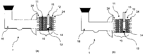
Figures 1(a) and (b) are schematic side sectioned views of a membraneless
direct liquid
fuel cell according to one embodiment of the invention having a movable guard
in a
partially closed (Figure 1(a)) and a fully opened (Figure 1(b)) position.
Figures 2(a) and (b) are perspective views of a spacer guard assembly of the
fuel cell
shown in Figures 1(a) and (b) wherein the guard is in a fully closed (Figure
2(a)) and a
fully opened (Figure 2(b)) position.
Figures 3(a) to (c) are conceptual schematic illustrations of the movable
guard being
moved from a fully opened position, (Figure 3(a)), to a fully closed position
(Figure 3(c))
to deactivate active regions of the fuel cell.
Figures 4(a) and (b) are a flowchart and a system diagram of a guard control
algorithm
programmed into a memory of a controller of an ideal fuel cell system.
7
CA 02737965 2011-03-21
WO 2010/043038
PCT/CA2009/001462
Figures 5(a) to (g) are schematic sectional side views of seven different
embodiments of
the movable guard in the fuel cell.
Figures 6(a) and (b) are schematic sectioned side views of the membraneless
fuel cell
with a perforated offset and a movable guard in partially closed (Figure 6(a))
and
opened (Figure 6(b)) positions, according to another embodiment of the
invention.
Figures 7(a) and (b) are front views of a movable perforated type guard in
opened
(Figure 7(a)) and partially closed (Figure 7(b)) positions according to
another
embodiment of the invention.
Figure 8 is a schematic perspective view of a movable shutter-type guard
according to
another embodiment of the invention.
Figure 9 shows multiple positions of a movable shutter-type guard according to
another
embodiment of the invention.
Figure 10(a) is a front view of an open spacer in a membraneless fuel cell
with a lateral
diffusion barrier and Figure 10(b) is a schematic side sectioned view of the
spacer with
a lateral diffusion barrier along with other components of the fuel cell
including a
movable guard according to yet another embodiment of the invention.
Figure 11 is a polarization and power curve, normalized to the effective open
active
area, for an electrode assembly with a guard placed within the open spacer.
Figure 12 is a graph of performance and power curves on an absolute basis for
various
open areas of the exemplary embodiment graphed in Figure 11.
Figure 13 is a graph of absolute power output and absolute crossover vs.
effective
active area of the exemplary embodiment graphed in Figure 11.
Figure 14 is a polarization and power curve, normalized to the effective open
active
area, for yet another exemplary embodiment having a guard covering an anode
and a
cathode.
8
CA 02737965 2011-03-21
WO 2010/043038
PCT/CA2009/001462
Figure 15 is a graph of performance and power curves on an absolute basis for
various
open areas of the exemplary embodiment graphed in Figure 14.
Figure 16 is a graph of absolute power output vs. effective active area of the
exemplary
embodiment graphed in Figure 14.
Figure 17 is a graph comparing the absolute polarization and power curves for
the
embodiments shown in Figures 5(a) to (c) and (g) with a 50% open area.
Figure 18 is a graph of absolute polarization and power curves for another
exemplary
embodiment having a filter paper spacer and a guard covering an anode.
Figure 19 is a graph of voltage and absolute current over time for a fuel cell
with a
manually operated guard on the cathode according to yet another exemplary
embodiment.
Figure 20 is a graph of absolute power over time of the fuel cell shown
graphed in
Figure 19.
Detailed Description of Embodiments of the Invention
Use of directional terms such as top, bottom, up and down are used in this
description
merely to assist the reader in understanding the described embodiments and are
not
intended to restrict the orientation, operation, or connection of the
embodiments or any
part thereof to the environment or to other structures.
The described embodiments provide a method and apparatus that enable a
controlled
activation and deactivation of selected segments of an active area of an
electrode
surface of a fuel cell to provide a variable effective active area of the
electrode surface.
The active area is the region where an electrochemical reaction takes place
(i.e.,
reactants, ionic conductor, electronic conductor come into triple phase
contact).
Particularly, the embodiments described herein all relate to fuel cells having
a movable
guard which can be operated to control the effective active area of the fuel
cell in
9
CA 02737965 2011-03-21
WO 2010/043038
PCT/CA2009/001462
selected regions of the fuel cell's electrode assembly, thereby controlling
the power
output of the fuel cell. The effective active areas are controlled by using
the movable
guard to controllably disrupt the triple phase boundary (TPB) in the selected
regions.
Use of the movable guard enables the fuel cell to be operated under an
optimized
condition, for example constant areal current density, voltage, areal power
density, areal
consumption and areal crossover during variable power demands. The movable
guard
can be used in fuel cells of different types, including gaseous reactant fuel
cells such as
PEM fuel cells, as well as direct liquid fuel cells such as DMFCs and the
direct liquid
fuel cells described in PCT application serial number PCT/CA2008/000843. In
some
embodiments, one or more movable guards are part of a membraneless direct
liquid
fuel cell and that are used to selectively block areas of an anode or a
cathode, or both,
of the fuel cell. The fuel cell can be a passive type, or an active type.
The embodiments rely on the principle of disrupting the TPB to control the
power output
of the fuel cell. As known in the fuel cell art, an electrochemical reaction
can only occur
at a TPB site where the electrolyte, reactants and an electrically connected
catalyst are
in contact. If the contact of these components can be controlled, certain
portions of the
area of an electrode can be activated and deactivated. In the described
embodiments,
the absolute power output under variable load can be controlled by the
deactivation of a
segment of the active electrode surface area using the movable guard. In some
embodiments, the guard also serves to prevent fuel crossover under variable
power
conditions. These embodiments are described below with reference to the
Figures.
Throughout this disclosure, "adjustable barrier means" may also be described
as a
"guard", and the two terms will be presumed to have the same meaning.
Fuel Cell Structure
According to a first embodiment and referring to Figure 1, a membraneless
direct liquid
fuel cell 1 comprises a membraneless electrode assembly 10 having a fluid
permeable
anode 11 comprising a porous layer that has an outer face and an opposite
inner face
that faces an inner face of a cathode 12. Located between the anode 11 and
cathode
12 is a spacer guard assembly 13 which comprises a frame that contacts the
periphery
CA 02737965 2011-03-21
WO 2010/043038
PCT/CA2009/001462
of the anode 11 and cathode 12 and serves to space the anode 11 and cathode 12
apart from each other, as well as to define an inner electrolyte chamber 14 in
between
the anode 11 and cathode 12. The spacer guard assembly 13 frame also serves as
a
fluid barrier in the lateral direction so that liquid electrolyte is contained
in the electrolyte
chamber 14. Spacing the electrodes 11, 12 from each other also prevents the
electrodes 11, 12 from touching and short circuiting.
A fuel reservoir 16 on the anodic side of the fuel cell 1 is fluidly coupled
to the outer face
of the anode 11 and contains a liquid fuel / electrolyte solution. The outer
face of the
cathode 12 is open to air which serves as the oxidant in the fuel cell
reaction. The
electrolyte chamber 14 and the anode electrode 11 are initialized with an
aqueous liquid
electrolyte. During normal fuel cell operation, when the fuel/electrolyte is
supplied to the
outer face of the anode 11, the fuel permeates through the anode outer face
and is
preferably substantially completely oxidized within the body of the anode 11,
such that
substantially no fuel passes the inner face of the anode porous layer into the
inner
chamber 14. However, the anode 11 can be designed to allow some fuel to
crossover
to the cathode 12, so long as the amount of crossover is low enough not to
reduce the
performance of the fuel cell 11 below a useful amount.
The liquid electrolyte is an ion conducting medium that provides ionic
communication
between the anode and cathode portions of the fuel cell 1. This communication
allows
the transport of ions (in this case, protons) from the fuel oxidizing anode 11
to the
cathode 12. In the present embodiments, an aqueous solution is used which
contains
both fuel and the electrolyte. A suitable liquid electrolyte is sulfuric acid;
however the
electrolyte medium may be any of a number of media that allow ionic
conduction. The
electrolyte medium may be acidic or alkaline in nature. A suitable fuel is
methanol;
however, the fuel can be an electroactive alcohol, electroactive organic acid,
or an
electroactive ether. More particularly, the fuel can be selected from the
group consisting
of propanol, methanol, formic acid, acetic acid, borohydride, ethanol,
dimethylether,
dimethoxymethane, trimethoxy methane, Trioxane, or other fuels suitable for
oxidation
in a direct fuel cell. The fuel can be in aqueous solution or be non-aqueous;
for
11
CA 02737965 2011-03-21
WO 2010/043038
PCT/CA2009/001462
example, the fuel can be 100% formic acid. One suitable fuel / electrolyte
solution for
use with the fuel cell 1 is 5 M methanol & 0.5M H2SO4/H20 solution.
In this embodiment, the fuel cell 1 uses air as a gaseous oxidant. While air
breathing
fuel cells offer a simple oxidant source, the oxidant is not restricted to
ambient air, and
can be other suitable oxidants as are known in the art, including oxygen,
hydrogen
peroxide, organic peroxides, chlorine, etc.
Catalyst particles, selected to effectively promote the oxidation of the fuel,
are
distributed between the outer and inner surfaces inside the anode body 11. The
catalyst
particles may be distributed substantially uniformly throughout the thickness
of the
porous layer between the anode's outer and inner surfaces, or may be
distributed non-
uniformly, for example in discrete layers or regions. Sufficient catalyst is
provided so
that a sufficient amount of fuel is reacted in the anode 11 for useful voltage
output by
the fuel cell 1. The thickness of the anode 11 and the quantity of catalyst
required will
depend for example on the amount of fuel supply to the anode 11 and the rate
of fluid
transport through the anode 11 and the rate of fuel consumption in the anode
11. In
one example of the anode 11, a porous material is provided comprising one or
more
layers of carbon particles mixed with a polymeric binder, and catalyst
particles are
distributed throughout the porous material (Figures 1(a) and (b) show a
multiple layered
anode 11). The porous material can be a carbon substrate (e.g. cloth, felt,
paper) and a
matrix of carbon particles and a polymeric binder which, along with the
catalyst particles
is distributed throughout the thickness of the carbon substrate. The porous
layer has
properties that provide sufficient strength and rigidity to serve as a support
structure for
the anode 11, given that the electrolyte chamber 14 results in an unsupported
gap
between the active areas of the anode 11 and cathode 12. The anode structure
can
incorporate a lateral diffusion barrier which prevents or impedes fuel from
flowing
laterally through the anode.
Similar to the anode 11, the cathode 12 comprises a porous layer having
properties that
provide sufficient strength and rigidity to serve as a support structure for
the cathode 12,
given that there is no membrane support structure between the anode 11 and
cathode
12
CA 02737965 2011-03-21
WO 2010/043038
PCT/CA2009/001462
12 in this embodiment. The cathode porous layer is loaded with catalytic
material that
serves to catalyze the oxidant (oxygen in air) as required by the
electrochemical
reaction. The cathode structure can incorporate a lateral diffusion barrier
which
prevents or impedes oxidant from flowing laterally through the cathode.
Referring to Figure 2, the spacer assembly 13 further comprises a guard
assembly 17
comprising a frame with a movable guard 15 located in between the anode 11 and
cathode 12 and which is movable into and out of the electrolyte chamber 14.
The
spacer assembly 13 has sufficient seals to ensure that there is no fluid
leakage between
the spacer assembly 13 and the anode 11 and cathode 12, and within the guard
assembly 17. The guard 15 is a solid plate which can be lowered into the
electrolyte
chamber 14 to sever part or all of the ionic contact between the anode 11 and
cathode
12. The guard 15 in this embodiment is made from an insulating material that
does not
substantially soak in or absorb the electrolyte solution sufficiently to
provide a path for
ionic conduction. Some examples of suitable materials for the guard 15 include
plastic
(PTFE), glass (borosilicate) or ceramic.
Referring to Figure 2, the guard 15 is vertically slidably mounted within the
frame of the
guard assembly 17, and is attached to a top arm of the guard assembly 17 by a
rotatable threaded rod 18. The rod 18 is connected to the arm of the guard
assembly
17 such that the rod 18 can freely rotate within the hole. The rod 18
threadably extends
through a threaded bore 19 in the guard 15 such that rotation of the rod 18
relative to
the bore 19 causes the guard 15 to move up and down in the guard assembly 17.
A
actuator 20 (shown schematically in Figure 2) is rotatably coupled to the rod
and is
controlled by a programmable controller 22 having a memory programmed with a
guard
control algorithm as will be described in more detail below. The actuator 20
can be a
motor or a solenoid valve or other controllable movement means as known in the
art.
Alternatively, the actuator 22 can be operated manually by a user instead of
by a
programmable controller. In yet another alternative embodiment, the rod 18 can
be
manually rotated instead of by an actuator.
13
CA 02737965 2011-03-21
WO 2010/043038
PCT/CA2009/001462
Optionally, an electrode diffusion barrier 24 can be positioned between the
fuel reservoir
16 and anode 11. The electrode diffusion barrier 24 serves to control the fuel
flux to the
anode 11. The electrode diffusion barrier 24 is made from perforated graphitic
material,
and serves the dual purpose of current collection and the control of methanol
flux. An
__ advantage of using a flexible graphitic sheet is that its physical
characteristics such as
thickness, pore size, shape and distribution can be controlled in a known way.
In this
way, various transport schemes can be designed. Although graphitic sheets are
used in
this embodiment, other perforated materials can also be used, such as a
perforated
metal foil. Alternatively, the electrode diffusion barrier 24 can be made from
any
__ perforated material and can be either electrically conductive and
insulating. When
electrically conductive, the diffusion barrier 24 can act as a current
collector for the fuel
cell 1. Optionally, a second electrode diffusion barrier 24 can be positioned
over the
outer surface of the cathode 12.
Referring to Figure 3, power output of the fuel cell 1 can be controlled by
controlling
__ movement of the movable guard 15. More particularly, all or part of the
active area in
the electrode assembly 10, which are herein defined as the electrocatalyst-
bearing
outer or inner faces of the anode 11 and cathode 12 exposed to the reactants
and/or
electrolyte (hereinafter referred to as "maximum potential active area") can
be blocked
by the guard 15. In this embodiment, the guard 15 is inserted in between the
anode 11
__ and cathode 12 to block the ionic connection between the electrodes 11, 12.
In other
embodiments as will be described later, the guard 15 can cover one or both of
the outer
surfaces of the anode 11 and cathode 12 thereby blocking reactants from
reaching the
respective outer surfaces electrodes 11, 12, and impeding the reactants from
reaching
the active areas within the electrode body behind the blocked surfaces. That
is, some
__ reactant that flows into the electrode body through the unblocked electrode
surfaces
may permeate laterally into the electrode body, the amount of permeated
reactant tends
to be minimal with selection of an appropriate electrode geometry and can be
reduced
by incorporating lateral diffusion barriers into the electrode body. In this
Figure, the
maximum potential active area of the electrode assembly 10 is represented by
the
circle, which corresponds to the electroactive anode and cathode outer or
inner
surfaces that are exposed to the reactants and/or electrolyte, and the guard
15 is
14
CA 02737965 2011-03-21
WO 2010/043038
PCT/CA2009/001462
represented by the square. In the areas of the electrode assembly 10 which are
not
blocked by the guard 15, the active nature of the fuel cell 1 remains (as
shown in
Figures 3(a)). However, in the surface areas which are blocked by the guard 15
(as
shown in Figure 3(b)) and the region of the electrode body behind the blocked
surface
area, the reactivity is substantially reduced or prevented. As the deactivated
regions
possess limited reactivity for the reaction of the fuel cell 1, the
contribution to the overall
power output from the deactivated regions is limited, and thus the total power
output of
the fuel cell 1 is reduced. For the embodiment shown in Figure 1, ionic
contact between
anode 11 and cathode 12 is completely severed when the guard 15 covers the
entire
maximum potential active area (as shown in Figure 3(c)), thus resulting in
substantially
no power output from the fuel cell 1.
The unblocked surface area of the electrode surfaces at any given position of
the guard
is referred to as the "effective active area" of the electrode 11, 12, as this
is the area
of the electrode 11, 12 which is still substantially electroactive. This
effective active area
15 can be changed depending on the load conditions of the fuel cell, and in
particular can
be changed by the controller 22 in response to varying load condition to
optimize the
operation of the fuel cell 1.
Operation
The controller 22 is programmed to selectively control the total power output
of the
direct liquid fuel cell 1 under variable load conditions. In one embodiment,
the controller
22 is programmed to vary the effective active area by moving the guard 15 in
response
to varying load conditions to maintain a substantially constant current
density and
consequently voltage and power density. Operating at a substantially constant
current
density offers several advantages: the system is always operating at an
optimal point
and the electrode assembly 10 design can be optimized to this point. As the
fuel
consumption and crossover rate per unit area (for example, as mol/cm2 s) is
always
approximately constant, it allows for the optimization of a single fuel
concentration. This
is useful for examples that incorporate the membraneless fuel cell approach to
ensure
the fuel crossover is low. In a conventional cell where the entire active area
is always
CA 02737965 2011-03-21
WO 2010/043038
PCT/CA2009/001462
open, changes in power conditions result in a varying current density and
consequently
different consumption rates per unit area and non-optimized performance.
In another embodiment, the controller 22 is programmed to selectively control
the total
power output of the direct liquid fuel cell 1 under variable load conditions
while operating
the fuel cell at a substantially constant voltage. The advantages of operating
at a
substantially constant voltage include: elimination of damage to electrical
components
due to large voltage fluctuations; higher DC-DC converter (voltage regulator)
efficiency
due to closely matched input/output voltages in the system; easier to detect
failure
modes (e.g., when the voltage of different open areas greatly deviates from
the constant
value); and less degradation of the fuel cell components and system, which can
lead to
longer fuel cell lifetimes.
According to another embodiment, the fuel cell 1 can also be used as a failure
detection
tool. For instance, in a single cell, the voltage should be approximately
constant for the
different active areas. If there is a large deviation from the expected value,
there may
be a failure in the open region of the single cell. In addition, the guard 15
can close the
affected region, and open a different section to compensate for the failure.
Referring to Figures 4(a) and 4(b), an exemplary control algorithm is
programmed into
the memory of the controller 22 for an ideal case where there is a direct 1:1
proportionality between the active area and power. Under non-ideal conditions,
other
components (e.g. DC-DC converter) and a more complicated control logic may be
required. The algorithm is executed by the controller 22 as a series of steps
of
instructions, comprising at step 100: first an electronic device A is
electrically coupled to
the fuel cell 1 and draws a load during operation. Then, at step 110, a
current sensor B
reads the desired current !device from the device A. Then at step 120, based
on load
read by the sensor, the controller 22 determines the position of the guard 15
that would
provide the effective active area that causes !device to equal the required
current.
Determining the appropriate position of the guard to obtain a desired current
can be
carried out as follows:
16
CA 02737965 2011-03-21
WO 2010/043038
PCT/CA2009/001462
1. Develop a polarization curve and decide on the desired current density and
voltage for the fuel cell 1. E.g 56 mA/cm2 and 0.15V. This polarization curve
can
be stored in the memory of the controller 22.
2. If necessary, connect multiple fuel cells 1 in parallel to accommodate the
electronic device input voltage. In general, electronic devices are designed
for a
constant voltage input. The power of the device changes according to the load.
3. Determine the maximum absolute current of the device A, e.g. 112mA. Using
the
desired current density obtained in step #1, determine the active area
required.
For example, assuming a current density is 56 mA/cm2 is chosen, a 2cm2 active
area is required for each cell.
The control logic is applied in the following example, with reference to
Figure 4(b)
1. Assume the device A requires a constant 0.15V. Also assume the current
required by the device can change from 112mA to 84mA to 56mA to 28mA (1, to
14). This results in corresponding power requirements of 16.8 mW, 12.6 mW, 8.4
mW, and 4.2 mW (P1 to P4)
2. The sensor B reads the change in absolute required current (mA) and sends
it to
the controller 22.
3. The controller 22 adjusts the active area of the fuel cell 1 to maintain
the
designed current density of 56mA/cm2. (e.g., 84mA 56 mA/cm2 = 1.5cm2;;
56mA 56 mA/cm2 = 1cm2 etc.)
4. On an absolute basis (mA) the fuel cell output will match the current
required by
the device A. As a consequence of maintaining a constant current density
(mA/cm2) for different effective active areas, the voltage will be constant.
5. The sensor B continues to monitor the current required and sends the
information to the controller 22 and the process is repeated.
17
CA 02737965 2011-03-21
WO 2010/043038
PCT/CA2009/001462
Other Embodiments
The guard 15 in the embodiment shown in Figures 1 to 4 is only one type of a
suitable
adjustable barrier means that can used to mitigate or prevent the presence of
one or
more phases of the TPB in a selected region of the fuel cell 1. As noted
above, the
adjustable barrier means serves to limit or disrupt the access of one or more
of the fuel,
electrolyte or oxidant to selected electrocatalyst-bearing regions (active
areas) of the
fuel cell 1.
Figures 5(a) to (g) show representative schematic examples of alternate
embodiments
of the fuel cell 1 that feature one or more guards 15 in different locations
in the fuel 1. In
particular, the guard 15 can cover a portion of the: a) anode active surface
area as
shown in Figure 5(a), b) area within the open spacer assembly 13 as discussed
above
and shown in Figures 1 and 5(b), c) cathode active surface area as shown in
Figure
5(c). Or, the fuel cell 1 can comprise one or more guards 15 in any
combination as
shown in Figures 5 (d) ¨ (g) to create an effective active surface area of the
electrode
11, 12 that is less than the maximum active surface area of the electrode 11,
12. In
some cases where a guard 15 is present at the anode 11 and/or spacer assembly
13,
crossover can also be prevented in the covered area under variable operation.
Note that
Figures 5(a), 5(c) and 5(g), wherein the guard or guards 15 are on the outer
face of the
anode 11 and/or cathode 12 are depicted as membraneless fuel cells, this
should not
be considered limiting as the embodiment will also work where there is a
membrane in
place of the spacer assembly 13.
While examples are shown in Figure 5 in which a diffusion barrier 24 is
optionally
present at the anode side of the electrode assembly 10, it is not a required
component
of the fuel cell 1. The diffusion barrier 24 may be preferred in some
embodiments; in
these embodiments, the guard 15 can be a perforated plate having perforations
that are
alignable with openings in the diffusion barrier 24.
As shown in the examples in Figures 5(a)-(g), when guards 15 are used to
deactivate
more than one area of the electrode assembly 10 - for example in Figure 5(g)
where
one guard 15 is used to deactivate an area at the anode 11 while another is
used to
18
CA 02737965 2011-03-21
WO 2010/043038
PCT/CA2009/001462
deactivate an area at the cathode 12 ¨ the guards 15 are preferably aligned so
that they
substantially overlap as viewed in the direction of the fuel flow through the
electrode
assembly 10.
Fuel cells which comprise the movable guard need not be planar. The guard(s)
used to
deactivate active surface areas of a fuel cell can be chosen such that they
sufficiently
match the general shape and/or surface contour of the appropriate surfaces
upon which
they act in order to provide interruption of the TPB. Examples include a
cylindrical fuel
cell with guard(s) that are hollow cylinders (or tube-like) in shape such that
they match
appropriately with the portion of the fuel cell (one example being an anode or
cathode)
upon which they are to act in order to deactivate an active surface area.
For approaches where the anode and/or cathode surface area is covered,
deactivation
occurs through the restriction of the reactant and/or electrolyte (for
example, methanol,
oxygen, acid, etc.) to the catalyst sites. For approaches where the open
spacer is
blocked, deactivation occurs by mitigating or severing the ionic contact
between the
anode and cathode, as already described above.
The guard 15 itself can be made from an electrically conductive or insulating
material
when used to cover the anode 11 and/or cathode 12 and an electrically
insulating
material when placed between the electrodes 11, 12 . A broad range of
acceptable
materials can be chosen for use as the guard 15, depending on the particular
environment (such as fuel, oxidant, electrolyte, temperature, pH, etc.) it
will be exposed
to in the fuel cell. For example, a guard 15 used for covering the anode 11
and/or
cathode 12 may be made from certain metals, plastics, glasses or ceramics. In
one
embodiment, the guard 15 covering the outer face of the anode 11 and/or
cathode 12
may be electrically conductive. In this way, the guard 15 has the dual role of
current
collection and power control. As stated, a guard 15 to be placed between the
electrodes
11, 12 should be made from an insulating material that does not substantially
soak in or
absorb the electrolyte solution sufficiently to provide a path for ionic
conduction ¨ that is,
a path for ionic conduction should not be present. Some examples of materials
for the
guard include plastic (PTFE), glass (borosilicate) or ceramic.
19
CA 02737965 2011-03-21
WO 2010/043038
PCT/CA2009/001462
While the guard 15 shown in the first embodiment is a solid plate movable
within the
spacer assembly 13, the guard can have other configurations. An example would
be to
use a perforated plate offset with an integrated diffusion barrier/current
collector on the
anode 11 and the current collector on the cathode (see Figures 6 and 7). The
superimposed perforated guard 15 can shift in order to open/close certain
pores in the
diffusion barrier 24. The perforated guard 15 can be single plate, or multiple
parallel
plates 28 as shown in Figures 7(a) and (b); a multiple plate design allows
more control
over which areas of the electrode assembly 10 are blocked. Each plate 28 is
connected
to and movable by the actuator (not shown), or be manually operated. The
action of
closing certain active areas is not limited to perforated materials.
Other alternative guard designs can be used, such as a shuttered gate having
multiple
movable parallel slats as shown in Figure 8, or a diaphragm shutter having
multiple
movable thin blades as shown in Figure 9.
Instead of the open spacer assembly 13 with a single opening between the anode
11
and cathode 12 as shown in Figure 1 to 4, an alternative embodiment uses an
electrically non-conductive porous separator which consists of a plurality of
openings.
Such a porous separator can be, for example, bars or a grid that extends
across the
anode and cathode surfaces. An exemplary design of such a porous separator 30
is
shown in Figure 10. Such a porous separator 30 can be used to provide a
lateral
diffusion barrier to further restrict activation of areas that have been
deactivated by the
guard due to lateral diffusion, while maintaining the high ionic conductivity
of a
substantially open spacer. In the example shown in Figure 10, when the guard
15 is not
present, the fuel cell 1 has two active areas (the two open halves of the
separator 30)
which can provide a power output. When the guard 15 is deployed so as to cover
the
bottom half of the separator 30, only one active area (top half) of the fuel
cell 1 can
provide power output, and the deactivated area (bottom half) does not
contribute
significantly to the power output of the fuel cell. In this example, the total
power output is
reduced by approximately 50% when the guard 15 is deployed as described.
CA 02737965 2011-03-21
WO 2010/043038
PCT/CA2009/001462
Other examples of a porous separator can be filter paper, glass filters or
frits, expanded
plastics etc. These porous separator with a plurality of openings can also be
used to
further limit the lateral diffusion of reactants and/or electrolyte in the
spacer area
between the anode and cathode, to allow for a greater restriction of the
access of the
reactants and/or electrolyte to the deactivated areas compared with an open
spacer
having a single large opening. The reduced mass transfer present in these
porous
spacers versus a single opening in an open spacer can aid in the deactivation
of
selected areas of the fuel cell. In addition, a means to control the lateral
diffusion within
the electrodes 11, 12 may optionally be used. For example, lateral diffusion
within a
carbon fiber paper based anode structure may be controlled by the presence of
added
materials in the matrix such as silicone, epoxy etc.
The movable guard can be used with a variety of fuel cell electrode assembly
structures, including those having a membrane electrode assembly, e.g. PEM
type, as
well as those having a membraneless electrode assembly as described above. In
other
embodiments of the invention, a fuel cell having a movable guard comprises a
conventional solid electrolyte material such as a PEM in a conventional
membrane
electrode assembly (MEA) (not shown). In embodiments having a PEM or similar
material to provide ionic conduction, an electrolyte solution is not
necessarily required
for operation of the fuel cell, in contrast to the other embodiments described
for the
membraneless fuel cell. In embodiments incorporating a PEM or similar MEA
types, the
guard used to controllably alter the effective active surface area of the fuel
cell can be
present at the anode, the cathode, or both in which case two guards would be
used.
The guard can be used to selectively control the effective active area of the
fuel cell 1
from 0% to 100% of the maximum potential active area of the electrode assembly
10. In
some embodiments it may be desired to control the effective active area of the
fuel cell
to only a limited range, rather than the entire range, of the maximum
potential active
area. For example, it may be desired to control the effective active area to 0-
90 %, or 0-
75% or 5-90%, or 5-75% of the maximum potential active area. When the guard is
used
to control the effective active area of the fuel cell to 0% of the maximum
potential active
area, this has the effect of "turning off' the fuel cell, which also provides
an advantage of
21
CA 02737965 2016-06-01
limiting or preventing fuel crossover on shut-down. The guard may be
configured to allow
gradual changes in the effective active area of the fuel cell. The guard may
be configured to
allow step-wise changes in the effective active area of the fuel cell.
Examples
The following examples are provided to aid in the illustration and description
of the
embodiments of the invention, without meaning to limit the invention to the
materials or
methods described in these examples. The scope of the claims should not be
limited by the
preferred embodiments set forth in the examples, but should be given the
broadest
interpretation consistent with the description as a whole. Furthermore,
alternative
embodiments and means of practicing the invention will become clear to one
skilled in the
art by these representative examples.
Electrode Assembly Preparation
Sheets of perforated graphitic foil, supplied by GrafTech International Ltd.,
were cut into
samples with a 25 mm diameter for use as a diffusion barrier at the anode
side. The foil also
acts as a current collector. The electrodes were prepared by a spray
deposition method
using an AccuSpray spray gun. For both the anode and cathode electrodes, a
sheet of
Etek-TGPH-060 carbon fibre paper with 20% wet proofing was used. On the anode,
a
loading of 4 mg=cm-2 carbon supported (Vulcan XC-72) 20 wt% Pt-Ru (1:1 atomic
ratio, or
a/o) catalyst with a Nafion ionomer loading of 30 wt% was applied. On the
cathode, a
loading of 1.36 mg.cm-2 carbon supported (Vulcan XC-72) Pt catalyst with a
Nation
ionomer loading of 30 wt% and a 1.00 mg=cm-2 Cabot carbon sublayer with 20 wt%
PTFE
was applied. From the electrode, smaller samples with a diameter of 16.5 mm
were cut out
for the electrode assembly holder. Prior to use, the anode was submerged in
0.5 M H2SO4
and placed in a vacuum oven for 15 minutes to ensure uptake of the electrolyte
into the
electrode structure.
The membraneless open ring shaped separator was made with Dow Corning
Siliastic J-
RTV silicone rubber and a curing agent. The spacer has an outer diameter of 25
mm and an
inner diameter of 16 mm with thickness of 0.5mm.
Guard Preparation for Open Spacer and Over the Electrodes
22
CA 02737965 2011-03-21
WO 2010/043038
PCT/CA2009/001462
Sheets of Kapton 100JP from Dupont or a hydrophobic material (e.g, Millipore
hydrophobic filter paper, Teflon etc) were used as materials for the
adjustable barrier
means (or "guard"). The guard was cut into circles with a 25 mm diameter. For
the
purpose of a simple demonstration of various power levels, the circles were
further cut
into 25%, 50% and 75% of the total open area.
Fuel Cell Performance Testing
The electrode assembly was incorporated into an electrode assembly holder with
a 2.0
cm2 active area. The performance of the air breathing membraneless DMFC was
recorded at ambient temperature and pressure (25 C, 1 atm) with a single
chamber
glass cell. In these examples, an aqueous fuel/electrolyte solution was used.
Polarization curves were obtained using a Solartron 1420E Multistat operated
in
galvanostatic mode.
Guard in open spacer
Figure 11 shows the performance, normalized to the open area, of an electrode
assembly with a guard in the open spacer (similar in principle to the
embodiment shown
in Figure 5(b)). In the segmented section, the anode and cathode are
deactivated by
ionic isolation. The close similarities in performance for the different open
areas
throughout the current density range demonstrate that the guard can be
effectively
implemented to deactivate the covered section. An important aspect to note is
that the
peak power density occurs at a constant current density value of -60 mA/cm2
for the
varying open area. The advantage of this is that the system is always
operating at an
optimal point and the electrode assembly can be optimized to this point. The
fuel
consumption and crossover rate per unit area (mol/cm2 s) is always constant
regardless
of absolute power output. This allows for the optimization of the fuel cell to
a single fuel
concentration. In a conventional cell where the entire active area is open,
changes in
power conditions result in a varying current density and consequently
different
consumption rates per unit area. The fuel stoichiometry must be adjusted
according to
the different power levels. In addition, the problem of crossover would
increase due to
the consumption of less fuel in the anode at low power (i.e., higher
concentration
23
CA 02737965 2011-03-21
WO 2010/043038
PCT/CA2009/001462
reaching the anode/spacer interface).
Constant Voltage
Figure 12 shows the performance and power curves on an absolute basis for the
various open areas. In this Figure it is noted that at each peak power level,
the voltage
remains constant at ¨0.15V. Advantages of a constant voltage include: the
elimination
of damage to electrical components due to large voltage fluctuations, higher
DC-DC
converter (voltage regulator) efficiency due to closely matched input/output
voltages,
easier to detect failure modes (e.g., when the voltage of different open areas
greatly
deviates from the constant value), less degradation etc.
Proportional absolute power and absolute crossover with open area
Figure 13 shows that the maximum absolute power and the absolute crososver is
proportional to the open area. The linear relationship for the selected open
areas shows
that the guard effectively deactivated the desired segments of the electrode
assembly.
Guard over electrodes
A fuel cell similar to that described above was assembled, with the guards
placed over
the anode and cathode, covering the fuel cell active region such that the
effective active
area was either 75%, 50%, and 25% of the total maximum active area. For
comparison,
the cell with 100% of the maximum active area exposed was also tested.
Representative data are shown in Figures 14 to 16
Lateral Diffusion Barrier
Figure 17 is a comparison of the absolute polarization and power curves for
configurations a) to c) and g) of Figure 5 with a 50% open area. All
arrangements, with
the exception of the case where only the anode was covered (Figure 5(a)),
resulted in a
reduction of absolute power of approximately 50% versus the baseline case of
100%
open area.
To further increase the effectiveness of the power control for the case where
a guard is
24
CA 02737965 2011-03-21
WO 2010/043038
PCT/CA2009/001462
only used on the anode, a fuel cell similar to that described above was
assembled,
except that the open spacer was replaced with a hydrophilic glass filter paper
(Fisherbrand G4 Inert Borosilicate). The filter paper was used to provide
resistance to
lateral fuel transport. Representative data for a fuel cell with a guard
covering the anode
are shown in Figure 18.
Dynamically Adjustable Guard
Figure 19 shows the voltage and current of the fuel cell with a manually
operated guard
on the cathode. When operating at an absolute current of 0.03A, the guard was
in a
partially closed position, such that 50% of the total active area of the fuel
cell was
exposed for reactivity. When operating at an absolute current of 0.06A, the
guard was
completely opened such that 100% of the total active area of the fuel cell was
exposed
and when the current returned to 0.03A, the guard returned to a partially
opened
position, such that 50% of the total active area of the fuel cell was exposed
for reactivity.
At each current change the voltage and current density (A/cm2) remained
constant.
Figure 20 shows that a manually operated guard can be used to increase and
decrease
the absolute power output of the fuel cell.