Note: Descriptions are shown in the official language in which they were submitted.
CA 02737976 2011-04-26
201000603
1
Winding arrangeiftent
The invention describes a winding arrangement for an armature
of an electric machine. The invention further describes an
armature for a generator, and a wind turbine with a genera-
tor.
For a large armature such as the rotor or stator of a wind
turbine, the coil windings are generally quite thick and
heavy owing to the physical dimensions of the generator and
the high currents induced. The windings can be made of thick
wire such as a multi-stranded wire, which is then wound onto
the armature, usually the stator. To this end, the armature
is usually made with multiple parallel slots arranged axially
along the outside for accommodating the windings. Instead of
wrapping the wire onto the armature, pre-shaped windings can
be formed and inserted or 'dropped into' the slots of the ar-
mature. Such a pre-shaped winding generally comprises a
closed loop comprising a "go" section and a "return" section"
held in two armature slots. A coil comprises a plurality of
such windings connected in series or parallel, and the con-
nection is usually made at one end of the armature where the
windings extend beyond the ends of the slots. As will be
known to the skilled person, successive windings of a coil
can be connected by allowing a strand of a multi-stranded
wire to extend from one winding of a coil to the next winding
of that coil, or by connecting windings of a coil to a bus
bar arranged circumferentially about the armature, or in any
other appropriate manner.
A multi-phase generator has the same number of coils as
phases. Here, the windings are placed in the slots such that
the slots for the "go" and "return" sections of one particu-
lar winding of a coil enclose or flank a number of slots for
the "go" and "return" sections of the remaining coils. The
windings of the different coils must overlap in some way at
CA 02737976 2011-04-26
201000603
2
the armature ends. To still permit a relatively straightfor-
ward stator winding assembly, the winding ends of the wind-
ings for a large stator are generally shaped so that a wind-
ing can be dropped into place without having to lift the pre-
vious winding. Because of the large dimensions involved, the
material used for the windings presents a considerable cost
factor. The winding overhang or winding head, i.e. the part
of the winding that extends beyond the stator slots, should
therefore be kept as short as possible. EP 2 166 645 Al de-
scribes an approach in which each coil is made of closed-loop
windings with a particular winding overhang geometry. The ge-
ometries of the different windings are shaped to permit the
windings of the neighbouring coils to pass each other in a
compact and close-fitting realisation, so that the overall
amount of copper used can be reduced. However, this approach
has the disadvantage that the winding overhangs have differ-
ent lengths owing to the different geometries, resulting in
different overall resistances of the coils. In turn, this
leads to load imbalances between the phases. To avoid such
imbalances, additional material must be included in the
'short' coils to effectively make these as long as the long-
est coil. Evidently, this adds to the overall cost of the
stator winding scheme and is therefore unsatisfactory.
It is therefore an object of the invention to provide an im-
proved coil winding arrangement.
The object of the invention is achieved by the winding ar-
rangement of claim 1 for an armature of an electric machine,
the armature of claim 12, the wind turbine of claim 13, and
the use of such a winding arrangement according to claim 14.
According to the invention, the winding arrangement for an
armature comprises a plurality of coils and a plurality of
distinct winding types, wherein the coils are arranged on the
armature such that each coil comprises the same number of
windings and the same number of each of the distinct winding
types.
CA 02737976 2011-04-26
201000603
3
An obvious advantage of the invention is that, since the
lengths of the windings are essentially the same for all
phases, less material is used compared to existing solutions
in which the end windings are extended to obtain a balanced
phase layout. Since the windings are all essentially of the
same length, all phases draw essentially the same current.
Furthermore, since the phases are balanced, the electrical
losses in the windings are constant and there are essentially
no voltage imbalances between the phases. This leads to a fa-
vourable reduction in the overall loss of the generator,
thereby favourably increasing the overall performance of the
electrical machine. Also, since it is not necessary in the
winding scheme according to the invention to add 'extra mate-
rial' to balance the coils, the material requirements in the
end windings is kept at a favourable minimum, so that the to-
tal weight of the generator is favourably reduced.
According to the invention, an armature for a generator com-
prises a plurality of coils, wherein the coils are arranged
or 'wound' on the armature according to such a winding ar-
rangement. Here, the term 'wound' is used in the established
sense, even though the windings of a large armature are gen-
erally too thick and heavy to be flexible.
A wind turbine according to the invention comprises a genera-
tor with a rotor and a stator, and a plurality of coils is
arranged on the stator according to such a winding arrange-
ment.
Such a winding arrangement is preferably used to wind the
coils on a stator of a generator for a wind turbine.
Particularly advantageous embodiments and features of the in-
vention are given by the dependent claims, as revealed in the
following description. Features of the different embodiments
can be combined as appropriate to give further embodiments.
CA 02737976 2011-04-26
201000603
4
The armature of the electric machine can be the stator or the
rotor, depending on the way in which the electric machine -
for example a generator - is constructed. Usually, however,
particularly in large generators, it is the stator that car-
ries the coil windings. In the following therefore, but with-
out restricting the invention in any way, it is assumed that
the stator carries the windings, although the winding scheme
according to the invention would be equally applicable to a
realisation in which the rotor of a generator carries the
windings.
Because of the large dimensions involved for a stator of a
large generator, as described above, the coils of the stator
are not wound using wire wrapped around the stator, as might
be the case for a small motor, but comprise pre-formed wind-
ings that can be inserted or even dropped into place in the
stator slots. The windings are successively inserted into
slots of the stator or stator segments. A coil can comprise a
series of pre-formed windings that are inserted into the ap-
propriate slots and then electrically connected. Preferably,
the windings can be realised as 'closed loop' windings, i.e.
each winding comprises a closed loop, and successive windings
of a coil are electrically connected after inserting into the
armature. Therefore, in a preferred embodiment of the inven-
tion, winding comprises a first ("go") winding body section
for placement in a first stator slot, a second ("return")
winding body section for placement in a second stator slot,
which first and second winding body sections are joined at
each end by an end section, which end section extends beyond
the stator in an essentially 180 fold so that the first and
second winding body sections are essentially parallel, and
wherein the end section of each distinct winding type com-
prises a distinct winding end geometry, whereby the distinct
winding end geometries of the different winding types allow
successive windings to be placed into the stator slots with-
out having to lift a previously placed winding. In the fol-
lowing, without restricting the invention in any way, it can
CA 02737976 2011-04-26
201000603
be assumed that a coil winding comprises a single layer wind-
ing.
A generator can have one or more phases, and therefore one or
5 more coils. Any number of different winding types could be
connected together for a coil. However, for the reasons ex-
plained above, the winding end geometries must be different
to allow the windings to overlap in the case of a multi-phase
generator. In a further preferred embodiment of the inven-
tion, the winding arrangement comprises an equal number of
coils and distinct winding types. This makes it straightfor-
ward to arrive at coils of essentially equal length.
Generally, the electric power distribution grid uses three-
phase electric power. Therefore, in a further preferred em-
bodiment of the invention, the winding arrangement according
to the invention comprises three coils and therefore three
distinct winding types in a three-phase, two-pole stator
winding arrangement.
To allow the winding overhangs of the three coils to cross in
a compact manner, in a further preferred embodiment of the
invention a first winding type comprises a first winding end
geometry, a second winding type comprises a second winding
end geometry, and a third winding type comprises a third
winding end geometry. Thereby, the first winding end geometry
preferably comprises an end section essentially in line with
the first and second winding body sections, i.e. the first
winding can essentially comprise a simple closed loop in a
plane. The remaining winding types can then be designed to
pass around the first winding type. Preferably, the second
winding end geometry comprises an end section tilted by es-
sentially 45 with respect to its first and second winding
body sections. For example, the end section of the second
winding type can be tilted 'upwards' or 'downwards'. The sec-
ond winding type also comprises a closed loop, so that the
winding end geometry in this case also comprises a 180 fold
so that the "go" and "return" sections can be slotted into
CA 02737976 2011-04-26
201000603
6
parallel axial stator slots. Preferably, the third winding
end geometry comprises an end section tilted by essentially
90 with respect to the first and second winding body sec-
tions. In a similar manner to the second winding type de-
scribed here, the end section of the third winding type can
be tilted 'upwards' or 'downwards'. The third winding type
also comprises a closed loop, so that the winding end geome-
try in this case also comprises a 180 fold, allowing the
"go" and "return" sections to be slotted into parallel axial
stator slots.
The three different winding types described above are easy to
manufacture and install, since successive windings can be
slotted into the stator slots without having to lift or move
previously inserted windings. For example, all windings of
the third type, with a 90 downward tilt, can be slotted onto
the stator. Then, all windings of the second type, with a 450
downward tilt, are slotted onto the stator. Finally, all
windings of the first type are inserted into the remaining
slots.
The windings for each coil can then be electrically con-
nected, for example using connections to bus bars arranged
circumferentially about the stator. Such a connection can be
made by allowing one or more wires or conductors of a winding
to make contact with an exposed bus bar.
Preferably, each coil comprises a distinct sequence of wind-
ing types. In a particularly preferred embodiment of the in-
vention, a first coil winding sequence comprises the first
winding type, second winding type and third winding type in
sequence; the second coil winding sequence comprises the sec-
ond winding type, third winding type and first winding type
in sequence; and the third coil winding sequence comprises
the third winding type, first winding type and second winding
type in sequence. Preferably, to ensure an optimally balanced
arrangement, each coil comprises the same number of windings,
and the total number of windings is evenly divisible by the
CA 02737976 2011-04-26
201000603
7
phase number of the generator. For example, for the three-
phase generator described above, three coils and three dif-
ferent winding types are used, and each coil preferably com-
prises 3N windings. In this way, each coil comprises the same
number of each of the different winding types, and the over-
all lengths of the coils are therefore essentially equal.
Such a winding scheme therefore provides a balanced load in a
simple and straightforward manner, while at the same time be-
ing favourably economical with the amount of metal used.
Other objects and features of the present invention will be-
come apparent from the following detailed descriptions con-
sidered in conjunction with the accompanying drawings. It is
to be understood, however, that the drawings are designed
solely for the purposes of illustration and not as a defini-
tion of the limits of the invention.
BRIEF DESCRIPTION OF THE DRAWINGS
Fig. 1 shows a schematic representation of a generator in a
wind turbine;
Fig. 2 shows a schematic representation of a prior art wind-
ing scheme for a stator of a generator;
Fig. 3 shows a stator segment with an arrangement of windings
according to the invention;
Fig. 4 shows a schematic representation of the end sections
of the windings if Fig. 3;
Fig. 5 shows a schematic representation of three coil se-
quences for a winding scheme according to the inven-
tion.
In the drawings, like reference numbers refer to like objects
throughout. Objects in the diagrams are not necessarily drawn
to scale.
DETAILED DESCRIPTION OF THE EMBODIMENTS
CA 02737976 2011-04-26
201000603
8
Fig. 1 shows a very simplified representation of a generator
4 in a wind turbine 5. For the sake of simplicity, only the
relevant components are indicated, and other components such
as a gearbox, controller, etc. are not shown. Pressure ex-
erted on the blades 50 of the wind turbine 5 causes the hub
51 or spinner to turn, thus causing a rotor 3 to rotate. The
rotor 3 is enclosed in a stator 2, about which a plurality of
coils (not shown in the diagram) is wound. The generator 4
operates as an induction motor, with a current being induced
in the coils. The principle of operation of such a generator
will be clear to the skilled person and need not be described
in detail here.
Because of the large currents (for example in the region of
200 - 500 Amps for 2 - 10 MW wind turbines), the windings
must be correspondingly dimensioned. For a wind turbine sta-
tor, the windings are typically made of stacked metal bars or
strips with a cross-section in the region of 20 mm x 100 mm.
These metal strips are held in stator slots arranged around
the outside of the stator, which can be up to 3 m in length.
Generally, because of the large dimensions (a wind turbine
stator can have a diameter in the region of 3 m to 7 m or
more), the stator generally comprises a set of stator seg-
ments.
A prior art winding scheme is illustrated with the aid of
Fig. 2, which shows a greatly simplified top view of a stator
segment 2a with slots 6 for accommodating windings 6a, 6b,
6c. Here, three coils are wound about the stator 2, and each
coil comprises a sequence of the same type of winding 6a, 6b,
6c. Each winding 6a, 6b, 6c is connected to another winding
6a, 6b, 6c of the same type by means of a connecting strip
7a, 7b, 7c or bus bar. A winding 6a, 6b, 6c is essentially a
flat strip, bent back on itself to give a closed loop, and
slotted into two parallel slots 6, whereby the two slots 6
required by one winding type 6a are separated by two further
slots 6 for the other two winding types 6b, 6c. The different
windings must cross each other and must be shaped to allow
CA 02737976 2011-04-26
201000603
9
the windings to be inserted into the slots in a straightfor-
ward manner. This means that the winding ends must be shaped
accordingly. For example, each winding end can be designed to
protrude some distance from the stator and can be bent or
twisted with a 180 fold so that the go and return sides are
at different heights. In this way, neighbouring windings can
simply be placed successively into the stator slots. However,
such a solution requires a certain amount of additional
metal, usually copper, to allow the winding overhangs to
cross, so that this type of solution is relatively costly.
The solution mentioned in the introduction, with differently
shaped winding end overhangs for each coil, is less costly,
but results in an unsatisfactory performance with load imbal-
ance owing to the different overall lengths of the coils.
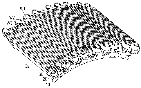
Fig. 3 shows a segment 2a of a stator with an arrangement of
windings 10, 20, 30 in a winding scheme 1 according to the
invention. Each winding 10, 20, 30 is shown as a metal strip
folded to give a closed loop. Three distinct winding types
W1, W2, W3 are shown. Each coil comprises a sequence of wind-
ings 10, 20, 30, whereby a coil sequence comprises each of
the different winding types W1, W2, W3 in turn, as will be
explained below.
Fig. 4 shows schematic representations of the end sections
10C, 20C, 30C of the different winding types Wl, W2, W3 shown
in Fig. 3. For the sake of clarity, each winding is shown on
its own, but it is to be understood that windings of differ-
ent types will be positioned in adjacent stator slots as
shown in Fig. 3. The first winding type W1 is essentially a
straightforward closed loop W1, and the end section 10C of
this winding type W1 essentially comprises a 180 fold. A
second winding type W2 has an end section 20C that does not
extend as far beyond the stator end as the first winding type
W1, but makes an approximately 45 bend before being folded
back. A third winding type W3 has an end section 30C that
also does not extend as far beyond the stator end as the
first winding type W1, and makes an approximately 90 bend
CA 02737976 2011-04-26
201000603
before being folded back. These different end-sections or
overhangs 10C, 20C, 30C allow the windings 10, 20, 30 to be
placed into the stator slots 6 in a straightforward manner.
For example, the stator can be wound by first inserting all
5 windings of the third type W3, then all windings of the sec-
ond type W2, and finally all windings of the first type W1.
Because of the winding end geometries, the windings can be
inserted without having to lift or move the previously placed
windings. The windings of a particular coil are then electri-
10 cally connected in a predefined sequence, as will be de-
scribed with the aid of Fig. 5, for example by joining a con-
ductor 10D, 20D, 30D of a winding 10, 20, 30 to a bus-bar B1,
B2, B3.
The upper part of Fig. 5 shows a schematic representation of
three coil sequences Si, S2, S3 for a winding scheme 1 ac-
cording to the invention. The order in which the windings are
connected are given by the sequences Si, S2, S3 shown in the
lower part of the diagram. The first coil winding sequence Si
for the first coil Cl comprises a winding of the first wind-
ing type W1, a winding of second winding type W2 and a wind-
ing of third winding type W3 in sequence. This pattern re-
peats for the entire first coil Cl. The second coil winding
sequence S2 for the second coil C2 comprises a winding of the
second winding type W2, a winding of third winding type W3
and a winding of first winding type W1 in sequence. This pat-
tern repeats for the entire second coil C2. The third coil
winding sequence S3 for the third coil C3 comprises a winding
of the third winding type W2, a winding of first winding type
W3 and a winding of second winding type Wl in sequence, and
this pattern repeats for the entire third coil C3. In the up-
per part of the diagram, the arrows indicate the current flow
direction in the different coils Cl, C2, C3 (so that the 'go'
winding sections of the first and third coils Cl, C3 occupy
slots on either side of the slot containing the 'return'
winding section of the second coil C2; while, the 'return'
winding sections of the first and third coils C1, C3 occupy
slots on either side of the slot containing the 'go' winding
CA 02737976 2011-04-26
201000603
11
section of the second coil C2). Since each coil Cl, C2, C3
comprises a sequence Si, S2, S3 in which the winding types
W1, W2, W3 appear essentially equally often, the overall
lengths of the coils Cl, C2, C3 are also essentially equal.
In this way, the winding arrangement according to the inven-
tion reduces or effectively eliminates load imbalances while
at the same time reducing the amount of metal required for
the windings. Although the windings are indicated here as
closed loops, the windings of the winding scheme 1 could
equally well be realised to be open at both ends, and the
connections could be made by bus-bars at both ends of the ar-
mature.
Although the present invention has been disclosed in the form
of preferred embodiments and variations thereon, it will be
understood that numerous additional modifications and varia-
tions could be made thereto without departing from the scope
of the invention. For example, the hub of the wind turbine
can turn a drive shaft connected to a gearbox, which can be
realised to turn the armature of a generator at a speed that
is more suitable for generating electricity for a power grid.
For the sake of clarity, it is to be understood that the use
of "a" or "an" throughout this application does not exclude a
plurality, and "comprising" does not exclude other steps or
elements.