Note: Descriptions are shown in the official language in which they were submitted.
CA 02738043 2013-02-05
1
DESCRIPTION
CATALYST SEPARATION SYSTEM
[TECHNICAL FIELD]
[0001]
The present invention relates to a catalyst separation system which separates
catalyst particles to recover hydrocarbons.
[BACKGROUND ART]
[0002]
As one method for synthesizing liquid fuels from a natural gas, a GTL (Gas To
Liquids: liquid fuel synthesis) technique of reforming a natural gas to
produce a synthesis
gas containing a carbon monoxide gas (CO) and a hydrogen gas (H2) as the main
components, synthesizing hydrocarbons using a catalyst with this synthesis gas
as a
source gas by the Fischer-Tropsch synthesis reaction (hereinafter referred to
as "FT
synthesis reaction"), and further hydrogenating and refining the hydrocarbons
to produce
liquid fuel products, such as naphtha (raw gasoline), kerosene, gas oil, and
wax, has
recently been developed.
[0003]
Various apparatuses have been studied in order to separate and recover
catalyst
particles from the liquid hydrocarbons including the catalyst particles which
have
deteriorated due to the reaction heat generated by the FT synthesis reaction,
the friction
with the inner wall of a flow line, the other external factors, etc.
CA 02738043 2011-03-21
0SP36390-36405(GTL0306)
2
As one of the apparatuses, for example, a recovery system shown in Patent
Document 1 can be utilized. This apparatus first heats the hydrocarbons
including the
catalyst particles inside a rotary kiln set in a heat chamber, and separates
them into
gasified hydrocarbons discharged in the axial direction from the middle part
of the rotary
kiln and catalyst particles discharged from an outer peripheral portion of the
rotary kiln.
Then, the gasified hydrocarbons are cooled down, condensed, and recovered by a
cooling
tower.
Further, as another apparatus, an apparatus is known which pressurizes the
liquid hydrocarbons including the catalyst particles, filters the liquid
hydrocarbons by a
single filter, and catches the catalyst particles larger than the diameter of
pores formed in
the filter, thereby separating the catalyst particles from the liquid
hydrocarbons.
[CITATION LIST]
[PATENT DOCUMENT]
[0004]
[Patent Document 1] Japanese Patent Unexamined Publication No. 6-17154
[SUMMARY OF THE INVENTION]
[PROBLEM THAT THE INVENTION IS TO SOLVE]
[0005]
However, when the catalyst particles are separated and recovered from the
slurry
including the liquid hydrocarbons, since it is necessary to provide the heat
chamber and
the cooling tower in a method shown in the above Patent Document 1, there is a
problem
in that the apparatus becomes large as a whole. Further, in the apparatus
which
separates the catalyst particles by the above filter, there is a possibility
that the catalyst
particles may pass through the filter when the catalyst particles with a small
particle size
are filtered, and the quality of liquid hydrocarbons to be recovered may
deteriorate.
CA 02738043 2011-03-21
0SP36390-36405(GTL0306)
=
3
[0006]
The present invention was made in view of such a problem, and the object
thereof is to provide a catalyst separation system which can suppress the
enlargement of
apparatuses, and deterioration of the hydrocarbons, thereby separating and
recovering
catalyst particles from the slurry including the liquid hydrocarbons.
[MEANS FOR SOLVING THE PROBLEM]
[0007]
In order to solve the above problem, the present invention suggests the
following means.
The catalyst separation system of the present invention is a catalyst
separation
system which separates catalyst particles from liquid hydrocarbons synthesized
by a
chemical reaction of a synthesis gas including a hydrogen and a carbon
monoxide as the
main components, and a slurry having solid catalyst particles suspended in a
liquid, the
catalyst separation system is provided with: a reactor; a storage tank which
stores the
slurry drawn from the reactor; a plurality of filters which filters the
slurry; and a filtrate
recovery vessel which recovers the filtrate which has passed through the
plurality of
filters, wherein the plurality of filters is disposed in series along a flow
line for the slurry
from the storage tank to the filtrate recovery vessel.
[0008]
Further, in the catalyst separation system, the chemical reaction may be a FT
synthesis reaction.
According to the present invention, the slurry including the catalyst
particles
flowed from the reactor body can be filtered multiple times by the filters
provided from
the upstream of the second flow line to the downstream thereof. For this
reason, when
the catalyst particles are separated and recovered from the slurry including
the liquid
CA 02738043 2011-03-21
0SP36390-36405(GTL0306)
4
hydrocarbons, the catalyst particles can be reliably prevented from being
mixed into the
liquid hydrocarbons to be recovered, and deterioration of the hydrocarbon
products can
be suppressed. Further, since the catalyst particles are separated from the
slurry by a
plurality of filters, it becomes unnecessary to separately provide accessory
devices, such
as a heat chamber and a cooling tower or a condenser. Therefore, it is
possible to keep
the system from being enlarged as a whole.
[0009]
Further, in the catalyst separation system, the pore diameter of the filter
provided
upstream of the flow line may be greater than the pore diameter of the filter
provided
downstream of the flow line among the plurality of filters.
According to the present invention, if all of the pore diameters of the
plurality of
filters are the same, the pores of the upstream filter will first be clogged
by the catalyst
particles. The catalyst separation system of the present invention is
configured so that
the pore diameter of the filter provided downstream of the second flow passage
is smaller
than the pore diameter of the filter provided upstream of the second flow
line. For this
reason, although the catalyst particles with a relatively small external
diameter which
have passed through the pores of the neighboring upstream filter clog the
filter disposed
downstream, the catalyst particles that are larger than the pore diameter of
the upstream
filter clog the upstream filter with a large pore diameter. In this way, the
external
diameter of the catalyst particles to be clogged will differ depending on
filters.
Accordingly, the catalyst particles can be prevented from clogging only the
upstream
filter unevenly, and thus, the slurry including the catalyst particles can be
prevented from
blocking the second flow line to hinder flow.
[0010]
Further, in the catalyst separation system, at least one of the plurality of
filters
CA 02738043 2011-03-21
0SP36390-36405(GTL0306)
=
may be a Nutsche filter.
In addition, the Nutsche filter referred to here means a filter of the type
which
performs suctioning and filtering by a vacuum pump or the like from one side
of cloth or
a wire screen, or a filter of the type which performs filtering by
pressurization from the
5 other side.
According to the present invention, the catalyst particles in the slurry can
be
effectively filtered.
[0011]
Further, in the catalyst separation system, a filter nearest to the filtrate
recovery
vessel among the plurality of filters may be made of sintered metal.
In addition, the filter made of sintered metal referred to here means a filter
which is obtained by overlapping metallic powder or nets, and heat-treating to
bind the
metallic powder or nets at a temperature below the melting point of the metal.
According to the present invention, even the catalyst particles with a small
external diameter, several micrometers, can be caught by the filters.
[0012]
Further, in the catalyst separation system, the plurality of filters may have
a first
filter which filters the slurry drawn from the storage tank, and a plurality
of second filters
which filters the slurry which has passed through the first filter, wherein a
portion of the
flow line may branch in parallel, the plurality of second filters may be
provided in each
branched flow line, and a switching device may be provided in the flow line
such that the
slurry is selectively flowed into the plurality of second filters.
[0013]
According to the present invention, for example, when the catalyst particles
clog
the pores of the filter and the slurry becomes difficult to flow while the
slurry is made to
CA 02738043 2013-11-12
6
flow to one branch flow line, it is possible to switch the branch flow lines
which allows
the slurry to flow to another branch flow line by the switching device.
Accordingly,
even when the catalyst particles have clogged the pores of the filter,
replacement with a
new filter can be made without stopping the flow of the slurry.
According to an aspect, the invention provides for a catalyst separation
system
for separating catalyst particles from liquid hydrocarbons synthesized by a
Fischer-Tropsch synthesis reaction of a synthesis gas including a hydrogen and
a carbon
monoxide as the main components, and a slurry having solid catalyst particles
suspended
in a liquid. The catalyst separation system comprises: a reactor; a storage
tank which
stores the slurry drawn from the reactor; a first filtering device which is
equipped with a
vessel body and a first filter put on the bottom of the inside of the vessel
body and is
configured to filter the slurry supplied to the vessel body from the storage
tank in the
vessel body; a first pipe line provided between the storage tank and the
vessel body of the
first filtering device and through which the slurry is fed from the storage
tank to the
vessel body, one end of the first pipe line being connected to the upper
section of the
vessel body; a second filtering device which is equipped with a second filter
of which the
mesh size is smaller than that of the first filter, and is configured to
filter the slurry
supplied to the second filtering device from the first filtering device; a
filtrate recovery
vessel which recovers a filtrate which has passed through the first and second
filtering
devices; a first nitrogen supply line which is connected to the storage tank,
and is
configured to supply nitrogen gas to vessel body of the first filtering device
via the
storage tank; and an agitating device configured to perform agitation of the
slurry in the
vessel body. A liquid surface of the slurry in the vessel body is compressed
by the
nitrogen gas supplied to the vessel body, and the slurry is agitated by the
agitating device
while the liquid surface of the slurry is compressed.
CA 02738043 2013-11-12
6a
[ADVANTAGE OF THE INVENTION]
[0014]
According to the catalyst separation system of the present invention, it is
possible to suppress the enlargement of the apparatuses, and deterioration of
the
hydrocarbons, thereby separating and recovering catalyst particles from the
slurry
including the liquid hydrocarbons.
[BRIEF DESCRIPTION OF THE DRAW[NGS]
[0015]
[FIG. 1] FIG. 1 is a schematic diagram showing the overall configuration of a
liquid fuel synthesizing system using a catalyst separation system of a first
embodiment
of the present invention.
[FIG. 2] FIG. 2 is a schematic diagram showing the overall configuration of
the
catalyst separation system of the first embodiment of the present invention.
[FIG 31 FIG. 3 is a flow chart showing the process of the catalyst separation
system of the first embodiment of the present invention.
[FIG 4] FIG. 4 is a schematic diagram showing the overall configuration of a
catalyst separation system of a second embodiment of the present invention.
[MODE FOR CARRYING OUT THE INVENTION]
[0016]
(First Embodiment)
Hereinafter, a first embodiment of a catalyst separation system according to
the
CA 02738043 2011-03-21
0SP36390-36405(GTL0306)
=
7
,
present invention will be described with reference to FIGS. 1 to 3.
FIG 1 is a schematic diagram showing the overall configuration of a liquid
fuel
synthesizing system 1 which synthesizes liquid fuels from a hydrocarbon
feedstock, such
as a natural gas, using a catalyst separation system 81 of the present
invention. The
liquid fuel synthesizing system 1 is a plant facility which carries out the
GTL process
which converts a hydrocarbon feedstock, such as natural gas, into liquid
fuels. The
catalyst separation system 81 is, for example, a system which is used when
individual
units which produce liquid-fuel products (which will be described later) of
the liquid fuel
synthesizing system 1 have stopped their operation, and which separates and
recovers
catalyst particles from a slurry including liquid hydrocarbons synthesized by
a chemical
reaction of a synthesis gas including a hydrogen gas and a carbon monoxide gas
as the
main components, and a slurry having solid catalyst particles suspended in a
liquid.
[0017]
As shown in FIG. 1, the liquid fuel synthesizing system 1 includes a synthesis
gas production unit 3, an FT synthesis unit 5, and an upgrading unit 7. The
synthesis
gas production unit 3 reforms a natural gas, which is a hydrocarbon feedstock,
to produce
a synthesis gas including a carbon monoxide gas and a hydrogen gas. The FT
synthesis
unit 5 produces liquid hydrocarbons from the produced synthesis gas by the
Fischer-Tropsch synthesis reaction. The upgrading unit 7 hydrogenates and
refines the
liquid hydrocarbons produced by the FT synthesis reaction to produce liquid
fuel
products (naphtha, kerosene, gas oil, wax, etc.). Hereinafter, components of
each of
these units will be described.
[0018]
First, the synthesis gas production unit 3 will be described. The synthesis
gas
production unit 3 mainly includes, for example, a desulfurizing reactor 10, a
reformer 12,
CA 02738043 2011-03-21
0SP36390-36405(GTL0306)
8
a waste heat boiler 14, vapor-liquid separators 16 and 18, a CO2 removal unit
20, and a
hydrogen separator 26. The desulfurizing reactor 10 is composed of a
hydrodesulfurizer,
etc., and removes sulfur components from a natural gas as a feedstock. The
reformer 12
reforms the natural gas supplied from the desulfurizing reactor 10, to produce
a synthesis
gas including a carbon monoxide gas (CO) and a hydrogen gas (H2) as the main
components. The waste heat boiler 14 recovers waste heat of the synthesis gas
produced in the reformer 12, to produce high-pressure steam. The vapor-liquid
separator 16 separates the water heated by heat exchange with the synthesis
gas in the
waste heat boiler 14 into a vapor (high-pressure steam) and a liquid. The
vapor-liquid
separator 18 removes a condensate from the synthesis gas cooled down in the
waste heat
boiler 14, and supplies a gas to the CO2 removal unit 20. The CO2 removal unit
20 has
an absorption tower 22 which removes carbon dioxide gas by using an absorbent
from
the synthesis gas supplied from the vapor-liquid separator 18, and a
regeneration tower
24 which desorbs the a carbon dioxide gas and regenerates the absorbent
including the
carbon dioxide gas. The hydrogen separator 26 separates a portion of the
hydrogen gas
included in the synthesis gas, the carbon dioxide gas of which has been
separated by the
CO2 removal unit 20. It is to be noted herein that the above CO2 removal unit
20 is not
necessarily provided depending on circumstances.
[0019]
Among them, the reformer 12 reforms a natural gas by using a carbon dioxide
and a steam to produce a high-temperature synthesis gas including a carbon
monoxide
gas and a hydrogen gas as the main components, by a steam and carbon-dioxide-
gas
reforming method expressed by the following chemical reaction formulas (1) and
(2).
In addition, the reforming method in this reformer 12 is not limited to the
example of the
above steam and carbon-dioxide-gas reforming method. For example, a steam
CA 02738043 2011-03-21
0SP36390-36405(GTL0306)
9
reforming method, a partial oxidation reforming method (PDX) using oxygen, an
autothermal reforming method (ATR) that is a combination of the partial
oxidation
method and the steam reforming method, a carbon-dioxide-gas reforming method,
and
the like can also be utilized.
[0020]
CH4 + H20 ---> CO + 3H2 === (1)
CH4 + CO2 ¨> 2C0 + 2H2 === (2)
[0021]
Further, the hydrogen separator 26 is provided on a branch line branched from
a
main line which connects the CO2 removal unit 20 or vapor-liquid separator 18
with the
bubble column reactor 30. This hydrogen separator 26 may be composed of, for
example, a hydrogen PSA (Pressure Swing Adsorption) device which performs
adsorption and desorption of hydrogen by using a pressure difference. This
hydrogen
PSA device has adsorbents (zeolitic adsorbent, activated carbon, alumina,
silica gel, etc.)
within a plurality of adsorption towers (not shown) which is arranged in
parallel. By
sequentially repeating processes including pressurizing, adsorption,
desorption (pressure
reduction), and purging of hydrogen in each of the adsorption towers, a high-
purity (for
example, about 99.999%) hydrogen gas separated from the synthesis gas can be
continuously supplied.
[0022]
In addition, the hydrogen gas separating method in the hydrogen separator 26
is
not limited to the example of the pressure swing adsorption method as in the
above
hydrogen PSA device. For example, it may be a hydrogen storing alloy
adsorption
method, a membrane separation method, or a combination thereof
[0023]
CA 02738043 2011-03-21
0SP36390-36405(GTL0306)
The hydrogen storing alloy method is, for example, a technique of separating
hydrogen gas using a hydrogen storing alloy (TiFe, LaNi5, TiFeo 7 - 09, Mno 3 -
0i, TiMni 5,
etc.) having a property which adsorbs or emits hydrogen by being cooled or
heated. By
providing a plurality of adsorption towers in which a hydrogen storing alloy
is contained,
5 and alternately repeating, in each of the adsorption towers, adsorption
of hydrogen by
cooling of the hydrogen storing alloy and emission of hydrogen by heating of
the
hydrogen storing alloy, hydrogen gas in the synthesis gas can be separated and
recovered.
[0024]
Further, the membrane separation method is a technique of separating hydrogen
10 gas having excellent membrane permeability out of a mixed gas, using a
membrane made
of a polymeric material, such as aromatic polyimide. Since this membrane
separation
method is not accompanied with a phase change, less energy for running is
required, and
the running cost is low. Further, since the structure of a membrane separation
device is
simple and compact, the facility cost required is low, and the facility area
required is
smaller. Moreover, since there is no driving device in a separation membrane,
and a
stable running range is wide, there is an advantage in that maintenance and
management
is easy.
[0025]
.Next, the FT synthesis unit 5 will be described. The FT synthesis unit 5
mainly
includes, for example, the bubble column reactor (reactor body) 30, a vapor-
liquid
separator 34, a separator 36, a vapor-liquid separator 38, and a first
fractionator 40. The
bubble column reactor 30 carries out the FT synthesis reaction of the
synthesis gas
produced in the above synthesis gas production unit 3, i.e., a carbon monoxide
gas and a
hydrogen gas, to produce hydrocarbons. The vapor-liquid separator 34 separates
the
water flowed and heated through a heat transfer pipe 32 disposed in the bubble
column
CA 02738043 2011-03-21
0SP36390-36405(GTL0306)
=
11
reactor 30 into a steam (medium-pressure steam) and a liquid. The separator 36
is
connected to a middle part of the bubble column reactor 30 to separate a
catalyst and a
liquid hydrocarbon product. The vapor-liquid separator 38 is connected to the
top of the
bubble column reactor 30 to cool down an unreacted synthesis gas and gaseous
hydrocarbon products. The first fractionator 40 distills the liquid
hydrocarbons supplied
via the separator 36 and the vapor-liquid separator 38 from the bubble column
reactor 30,
and separates and refines the liquid hydrocarbons into individual fractions
according to
boiling points.
[0026]
Among them, the bubble column reactor 30, which is an example of a reactor
which synthesizes liquid hydrocarbons from a synthesis gas, functions as an FT
synthesis
reactor which synthesizes liquid hydrocarbons from the synthesis gas by the FT
synthesis
reaction. The bubble column reactor 30 is composed of, for example, a bubble
column
slurry bed type reactor in which a slurry consisting mainly of catalyst
particles and
medium oil is contained inside a tower type container. This bubble column
reactor 30
produces gaseous or liquid hydrocarbons from the synthesis gas by the FT
synthesis. In
detail, in this bubble column reactor 30, the synthesis gas that is a source
gas is supplied
as bubbles from a sparger at the bottom of the bubble column reactor 30, and
passes
through the slurry, and in a suspended state, a hydrogen gas and a carbon
monoxide gas
undergo a synthesis reaction, as shown in the following chemical reaction
formula (3).
[0027]
2nH2 + nC0 -(CH2)-n + nH20 === (3)
[0028]
In addition, the catalyst particles may deteriorate due to the heat generated
CA 02738043 2011-03-21
=
0SP36390-36405(GTL0306)
12
during the FT synthesis reaction, the friction with the inner wall of a flow
line, etc.
Further, since this FT synthesis reaction is an exothermic reaction, the
bubble column
reactor 30, which is a heat exchanger type reactor within which the heat
transfer pipe 32
is disposed, is adapted such that, for example, water (BFW: Boiler Feed Water)
is
supplied as a coolant so that the reaction heat of the above FT synthesis
reaction can be
recovered as a medium-pressure steam by the heat exchange between the slurry
and the
water.
[0029]
Finally, the upgrading unit 7 will be described. The upgrading unit 7
includes,
for example, a wax fraction hydrocracking reactor 50, a kerosene and gas oil
fraction
hydrotreating reactor 52, a naphtha fraction hydrotreating reactor 54, vapor-
liquid
separators 56, 58 and 60, a second fractionator 70, and a naphtha stabilizer
72. The wax
fraction hydrocracking reactor 50 is connected to the bottom of the first
fractionator 40.
The kerosene and gas oil fraction hydrotreating reactor 52 is connected to the
middle part
of the first fractionator 40. The naphtha fraction hydrotreating reactor 54 is
connected
to an upper part of the first fractionator 40. The vapor-liquid separators 56,
58 and 60
are provided so as to correspond to the hydrogenation reactors 50, 52 and 54,
respectively.
The second fractionator 70 separates and refines the liquid hydrocarbons
supplied from
the vapor-liquid separators 56 and 58 according to boiling points. The naphtha
stabilizer 72 distills liquid hydrocarbons of a naphtha fraction supplied from
the
vapor-liquid separator 60 and the second fractionator 70. Then the naphtha
stabilizer 72
discharges butane and components lighter than butane as a flare gas, and
separates and
recovers components having a carbon number of five or more as a naphtha
product.
[0030]
Next, a process (GTL process) of synthesizing liquid fuel from a natural gas
by
CA 02738043 2011-03-21
0SP36390-36405(GTL0306)
13
the liquid fuel synthesizing system 1 configured as above will be described.
[0031]
A natural gas (whose main component is CH4) as a hydrocarbon feedstock is
supplied to the liquid fuel synthesizing system 1 from an external natural gas
supply
source (not shown), such as a natural gas field or a natural gas plant. The
above
synthesis gas production unit 3 reforms this natural gas to produce a
synthesis gas (mixed
gas including a carbon monoxide gas and a hydrogen gas as main components).
[0032]
Specifically, first, the above natural gas is supplied to the desulfurizing
reactor
10 along with the hydrogen gas separated by the hydrogen separator 26. The
desulfurizing reactor 10 hydrogenates and desulfurizes sulfur components
included in the
natural gas using the hydrogen gas, with, for example, a ZnO catalyst. By
desulfurizing
the natural gas in advance in this way, it is possible to prevent deactivation
of catalysts
used in the reformer 12, the bubble column reactor 30, etc. by sulfur
components.
[0033]
The natural gas (may also contain a carbon dioxide) desulfurized in this way
is
supplied to the reformer 12 after the carbon dioxide (CO2) gas supplied from a
carbon-dioxide supply source (not shown) and the steam generated in the waste
heat
boiler 14 are mixed therewith. The reformer 12 reforms a natural gas by using
a carbon
dioxide and a steam to produce a high-temperature synthesis gas including a
carbon
monoxide gas and a hydrogen gas as the main components, by a steam and
carbon-dioxide-gas reforming method. At this time, the reformer 12 is supplied
with,
for example, a fuel gas for a burner disposed in the reformer 12 and air, and
the reaction
heat required for the above steam and CO2 reforming reaction, which is an
endothermic
reaction is provided with the heat of combustion of the fuel gas in the
burner.
CA 02738043 2011-03-21
0SP36390-36405(GTL0306)
=
14
[0034]
The high-temperature synthesis gas (for example, 900 C, 2.0 MPaG) produced
in the reformer 12 in this way is supplied to the waste heat boiler 14, and is
cooled down
by the heat exchange with the water which flows through the waste heat boiler
14 (for
example, 400 C), thus the waste heat is recovered. At this time, the water
heated by the
synthesis gas in the waste heat boiler 14 is supplied to the vapor-liquid
separator 16.
From this vapor-liquid separator 16, a gas component is supplied to the
reformer 12 or
other external devices as a high-pressure steam (for example, 3.4 to 10.0
MPaG), and
water as a liquid component is returned to the waste heat boiler 14.
[0035]
Meanwhile, the synthesis gas cooled down in the waste heat boiler 14 is
supplied to the absorption tower 22 of the CO2 removal unit 20, or the bubble
column
reactor 30, after a condensate is separated and removed from the synthesis gas
in the
vapor-liquid separator 18. The absorption tower 22 absorbs a carbon dioxide
gas
included in the synthesis gas into the retained absorbent, to separate the
carbon dioxide
gas from the synthesis gas. The absorbent including the carbon dioxide gas
within this
absorption tower 22 is introduced into the regeneration tower 24, the
absorbent including
the carbon dioxide gas is heated and subjected to stripping treatment with,
for example, a
steam, and the resulting desorbed carbon dioxide gas is recycled to the
reformer 12 from
the regeneration tower 24, and is reused for the above reforming reaction.
[0036]
The synthesis gas produced in the synthesis gas production unit 3 in this way
is
supplied to the bubble column reactor 30 of the above FT synthesis unit 5. At
this time,
the composition ratio of the synthesis gas supplied to the bubble column
reactor 30 is
adjusted to a composition ratio (for example, H2:C0=2:1 (molar ratio))
suitable for the
CA 02738043 2011-03-21
.
0SP36390-36405(GTL0306)
FT synthesis reaction. In addition, the pressure of the synthesis gas supplied
to the
bubble column reactor 30 is raised to a pressure (for example, about 3.6 MPaG)
suitable
for the FT synthesis reaction by a compressor (not shown) provided in a pipe
which
connects the CO2 removal unit 20 with the bubble column reactor 30.
5 [0037]
Further, a portion of the synthesis gas, the carbon dioxide gas of which has
been
separated by the above CO2 removal unit 20, is also supplied to the hydrogen
separator
26. The hydrogen separator 26 separates the hydrogen gas included in the
synthesis gas,
by the adsorption and desorption (hydrogen PSA) utilizing a pressure
difference as
10 described above. This separated hydrogen is continuously supplied from a
gas holder
(not shown), etc. via a compressor (not shown) to various hydrogen-utilizing
reaction
devices (for example, the desulfurizing reactor 10, the wax fraction
hydrocracking
reactor 50, the kerosene and gas oil fraction hydrotreating reactor 52, the
naphtha fraction
hydrotreating reactor 54, etc.) which perform predetermined reactions
utilizing the
15 hydrogen within the liquid fuel synthesizing system 1.
[0038]
Next, the above FT synthesis unit 5 synthesizes liquid hydrocarbons by the FT
synthesis reaction from the synthesis gas produced by the above synthesis gas
production
unit 3.
[0039]
Specifically, the synthesis gas from which the carbon dioxide gas has been
separated from in the above CO2 removal unit 20 flows in from the bottom of
the bubble
column reactor 30, and flows up in the catalyst slurry contained in the bubble
column
reactor 30. At this time, within the bubble column reactor 30, the carbon
monoxide gas
and hydrogen gas which are included in the synthesis gas react with each other
by the FT
CA 02738043 2011-03-21
=
0SP36390-36405(GTL0306)
16
synthesis reaction, thereby producing hydrocarbons. Moreover, by flowing water
through the heat transfer pipe 32 of the bubble column reactor 30 at the time
of this
synthesis reaction, the reaction heat of the FT synthesis reaction is removed,
and the
water heated by this heat exchange is vaporized into a steam. As for this
steam, the
water liquefied in the vapor-liquid separator 34 is returned to the heat
transfer pipe 32,
and a gas component is supplied to an external device as a medium-pressure
steam (for
example, 1.0 to 2.5 MPaG).
[0040]
The liquid hydrocarbons synthesized in the bubble column reactor 30 in this
way
are drawn from the middle part of the bubble column reactor 30, and are
introduced to
the separator 36. The separator 36 separates a catalyst (solid component), and
a liquid
component including a liquid hydrocarbon product in the drawn slurry. A part
of the
separated catalyst is supplied to the bubble column reactor 30, and the liquid
component
is supplied to the first fractionator 40. From the top of the bubble column
reactor 30, an
unreacted synthesis gas, and a gas component of the synthesized hydrocarbons
are
introduced into the vapor-liquid separator 38. The vapor-liquid separator 38
cools down
these gases to separate some condensed liquid hydrocarbons to introduce them
into the
first fractionator 40. Meanwhile, as for the gas component separated in the
vapor-liquid
separator 38, the unreacted synthesis gas (CO and H2) is returned to the
bottom of the
bubble column reactor 30, and is reused for the FT synthesis reaction.
Further, the
emission gas (flare gas) other than the target products, including as the main
component
hydrocarbon gas having a small carbon number (C4 or less), is introduced into
an external
combustion facility (not shown), is combusted therein, and is then emitted to
the
atmosphere.
[0041]
CA 02738043 2011-03-21
=
0SP36390-36405(GTL0306)
17
Next, the first fractionator 40 heats the liquid hydrocarbons (whose carbon
numbers are various) supplied via the separator 36 and the vapor-liquid
separator 38 from
the bubble column reactor 30 as described above, to fractionally distill the
liquid
hydrocarbons using a difference in boiling points. Thereby, the first
fractionator 40
separates and refines the liquid hydrocarbons into a naphtha fraction (whose
boiling point
is lower than about 150 C), a kerosene and gas oil fraction (whose boiling
point is about
150 to 350 C), and a wax fraction (whose boiling point is higher than about
350 C).
The liquid hydrocarbons (mainly C21 or more) as the wax fraction drawn from
the bottom
of the first fractionator 40 are transferred to the wax fraction hydrocracking
reactor 50,
the liquid hydrocarbons (mainly C to C20) as the kerosene and gas oil fraction
drawn
from the middle part of the first fractionator 40 are transferred to the
kerosene and gas oil
fraction hydrotreating reactor 52, and the liquid hydrocarbons (mainly C5 to
C10) as the
naphtha fraction drawn from the upper part of the first fractionator 40 are
transferred to
the naphtha fraction hydrotreating reactor 54.
[0042]
The wax fraction hydrocracking reactor 50 hydrocracks the liquid hydrocarbons
as the wax fraction with a large carbon number (approximately C21 or more),
which has
been supplied from the bottom of the first fractionator 40, by using the
hydrogen gas
supplied from the above hydrogen separator 26, to reduce the carbon number to
C20 or
less. In this hydrocracking reaction, hydrocarbons with a small carbon number
and with
low molecular weight are produced by cleaving the C-C bonds of the
hydrocarbons with
a large carbon number, using a catalyst and heat. A product including the
liquid
hydrocarbons hydrocracked in this wax fraction hydrocracking reactor 50 is
separated
into a gas and a liquid in the vapor-liquid separator 56, the liquid
hydrocarbons of which
are transferred to the second fractionator 70, and the gas component
(including a
CA 02738043 2011-03-21
0SP36390-36405(GTL0306)
18
hydrogen gas) of which is transferred to the kerosene and gas oil fraction
hydrotreating
reactor 52 and the naphtha fraction hydrotreating reactor 54.
[0043]
The kerosene and gas oil fraction hydrotreating reactor 52 hydrotreats liquid
hydrocarbons (approximately C11 to C20) as the kerosene and gas oil fractions
having a
substantially middle carbon number, which have been supplied from the middle
part of
the first fractionator 40, by using the hydrogen gas supplied via the wax
fraction
hydrocracking reactor 50 from the hydrogen separator 26. In this hydrotreating
reaction,
in order to obtain mainly branched chain saturated hydrocarbons, the liquid
hydrocarbons
are isomerized, and a hydrogen is added to unsaturated bonds of the above
liquid
hydrocarbons to saturate the liquid hydrocarbons. As a result, a product
including the
hydrotreated liquid hydrocarbons is separated into a gas and a liquid in the
vapor-liquid
separator 58, the liquid hydrocarbons of which are transferred to the second
fractionator
70, and the gas component (including hydrogen gas) of which is reused for the
above
hydrogenation reaction.
[0044]
The naphtha fraction hydrotreating reactor 54 hydrotreats liquid hydrocarbons
(approximately C10 or less) as the naphtha fraction with a low carbon number,
which
have been supplied from the upper part of the first fractionator 40, by using
the hydrogen
gas supplied via the wax fraction hydrocracking reactor 50 from the hydrogen
separator
26. As a result, a product including the hydrotreated liquid hydrocarbons
is separated
into a gas and a liquid in the vapor-liquid separator 60, the liquid
hydrocarbons of which
are transferred to the naphtha stabilizer 72, and the gas component (including
a hydrogen
gas) of which is reused for the above hydrogenation reaction.
[0045]
CA 02738043 2011-03-21
0SP36390-36405(GTL0306)
=
19
Next, the second fractionator 70 distills the liquid hydrocarbons supplied
from
the wax fraction hydrocracking reactor 50 and the kerosene and gas oil
fraction
hydrotreating reactor 52 as described above. Thereby, the second fractionator
70
separates and refines the liquid hydrocarbons into hydrocarbons (whose boiling
point is
lower than about 150 C) with a carbon number of C10 or less, kerosene (whose
boiling
point is about 150 to 250 C), gas oil (whose boiling point is about 250 to 350
C), and
uncracked wax fraction (whose boiling point is higher than about 350 C) from
the wax
fraction hydrocracking reactor 50. The gas oil is drawn from a lower part of
the second
fractionator 70, and the kerosene is drawn from a middle part thereof.
Meanwhile,
hydrocarbons with a carbon number of Cio or less are drawn from the top of the
second
fractionator 70, and is supplied to the naphtha stabilizer 72.
[0046]
Moreover, the naphtha stabilizer 72 distills the hydrocarbons with a carbon
number of C10 or less, which have been supplied from the above naphtha
fraction
hydrotreating reactor 54 and second fractionator 70. Thereby, the naphtha
stabilizer 72
separates and refines naphtha (C5 to C10) as a product. Accordingly, a high-
purity
naphtha is drawn from a lower part of the naphtha stabilizer 72. Meanwhile,
the
emission gas (flare gas) other than products, which contains as the main
component
hydrocarbons with a predetermined carbon number or less (C4 or less), is
discharged from
the top of the naphtha stabilizer 72.
[0047]
FIG. 2 shows, for example, the catalyst separation system 81 of the present
invention used when individual units of the liquid fuel synthesizing system 1
have
stopped their operation as described above.
The catalyst separation system 81 includes the bubble column reactor 30, a
first
CA 02738043 2011-03-21
0SP36390-36405(GTL0306)
flow line 83 for drawing the slurry including the catalyst particles from the
bubble
column reactor 30, a storage tank which stores the drawn slurry, i.e., a waste
catalyst
receiving tank 85, a second flow line 84 for processing the slurry in the
waste catalyst
receiving tank 85, and a plurality of filters (the details thereof will be
described later)
5 provided towards the downstream from the upstream of the second flow line
84.
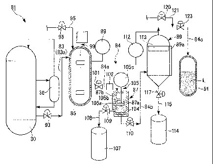
[0048]
The first flow line 83 is constituted by a pipe 83a, the second flow line 84
includes pipes 84a, 84b, and 84c, and the waste catalyst receiving tank 85, a
first filtering
device 87, a second filtering device 89, and a filtrate recovery vessel 91 are
provided in
10 this order from the upstream. The bubble column reactor 30 is connected
to one end of
the pipe 83a, the waste catalyst receiving tank 85 is connected between the
other end of
the pipe 83a, and one end of the pipe 84a, the first filtering device 87 is
connected
between the other end of the pipe 84a and one end of the pipe 84b, and the
second
filtering device 89 is connected between the other end of the pipe 84b and one
end of the
15 pipe 84c. The filtrate recovery vessel 91 is connected to the other end
of the pipe 84c
opposite to its one end to which the second filtering device 89 is connected.
The waste catalyst receiving tank 85 is a tank which temporarily stores the
slurry,
the first filtering device 87 and the second filtering device 89 are devices
which filter
solids, such as catalyst particles, from the slurry, and the filtrate recovery
vessel 91 is a
20 vessel which holds a filtrate L obtained by filtering the slurry.
[0049]
A first gate valve 93 for opening and closing the pipe 83a is installed in the
pipe
83a connected between the bubble column reactor 30 and the waste catalyst
receiving
tank 85. The "opening the pipe" referred to here means that the slurry can be
made to
flow through a pipe, and "closing the pipe" means that the slurry cannot be
made to flow
CA 02738043 2011-03-21
0SP36390-36405(GTL0306)
21
through the pipe.
A first nitrogen supply line 95 for supplying nitrogen into the waste catalyst
receiving tank 85 is connected to an upper part of the waste catalyst
receiving tank 85,
and a second gate valve 96 for opening and closing the line is installed in
the first
nitrogen supply line 95.
A liquid level detector 98 which detects the height of the liquid level of the
slurry held inside is attached to the waste catalyst receiving tank 85, and an
agitator 99
for agitating the slurry is installed in the waste catalyst receiving tank. In
addition, in
the liquid level detector 98, a display device (not shown) provided in the
liquid level
detector may display "HIGH" when the waste catalyst receiving tank 85 is
filled with the
slurry, and its liquid level becomes higher than a predetermined height, and
may display
"EMPTY" when the slurry is exhausted from the waste catalyst receiving tank
85.
[0050]
A third gate valve 101 for opening and closing the pipe 84a, and a measuring
instrument 102 for metering the flow rate of the slurry which flows through
the pipe 84a
are attached to the pipe 84a connected between the waste catalyst receiving
tank 85 and
the first filtering device 87.
The first filtering device 87 is equipped with a cylindrical vessel body 87a
which
holds the slurry, a first filter 104 that is a Nutsche filter for filtering
the slurry, a liquid
level detector 87b which detects the liquid level of the slurry including the
catalyst
particles in the vessel body 87a, an agitating/discharging device 105 which
performs
agitation of the slurry, and discharge of the solids filtered by the first
filter 104, and a first
solid conveyance flow line 108 which conveys the filtered solids to be held in
a first
waste catalyst drum 107.
The Nutsche filter is generally a filter of the type which performs suctioning
and
CA 02738043 2011-03-21
0SP36390-36405(GTL0306)
22
filtering by a vacuum pump or the like from one side of cloth or a wire
screen, or a filter
of the type which performs filtering by pressurization from the other side,
and the first
filter 104 of this embodiment is configured such that the mesh thereof is 400
to 800
meshes, i.e., the diameter of pores formed in the first filter 104 is 31 to 63
pm.
The agitating/discharging device 105 has an agitating blade 105a which is
disposed within the vessel body 87a to rotate around the axis of the vessel
body 87a
and move in parallel in the axis direction thereof, a shaft member 105b
connected to the
agitating blade 105a at one end, and a agitating blade driving motor 105c
which is
connected to the other end of the shaft member 105b and generates a driving
force which
rotates or moves the agitating blade 105a.
Further, a valve 109 for opening and closing the first solid conveyance flow
line
108 is attached to the first solid conveyance flow line 108.
[0051]
A fourth gate valve 110 for opening and closing the pipe 84b is installed in
the
pipe 84b connected between the first filtering device 87 and the second
filtering device
89.
The second filtering device 89 includes a differential pressure gage 112 which
measures the pressure difference between the inside of the second filtering
device and the
pipe 84c immediately after the second filtering device 89, a second filter 113
that is a
filter made of sintered metal (hereinafter referred to as a "sintered metallic
filter") which
is disposed inside, and a liquid level detector 89a which detects the liquid
level of the
slurry in the second filtering device 89. It is possible to form minute pores
in the
sintered metallic filter, and in this embodiment, the pore diameter of the
second filter 113
is set so as to be 10 or less, and preferably 5 m or less. That is, two
filters
provided in the catalyst separation system 81 are configured so that the pore
diameter of
CA 02738043 2011-03-21
0SP36390-36405(GTL0306)
23
the second filter 113 disposed downstream becomes smaller than the pore
diameter (31 to
63 iAm) of the first filter 104 disposed upstream.
In the differential pressure gage 112, a display device (not shown) provided
in
the differential pressure gage may display "HIGH" when the second filter 113
is clogged
due to the catalyst particles or the like, and the pressure loss between the
upstream and
the downstream of the second filter 113 is larger than a predetermined value,
and may
display "LOW" when the pressure loss is smaller than a predetermined value.
[0052]
A second solid conveyance flow line 115 which conveys the solids filtered by
the second filtering device 89 to be held in the second waste catalyst drum
114 is
provided under the second filtering device 89. A seventh gate valve 117 for
opening
and closing the second solid conveyance flow line 115 is provided in the
second solid
conveyance flow line 115.
In the pipe 84c connected between the second filtering device 89 and the
filtrate
recovery vessel 91, a second nitrogen supply line 121 which supplies nitrogen
into the
pipe 84c, and is opened and closed by a sixth gate valve 120 is connected to
the
downstream of a place where the pressure on the side of the pipe 84c is
measured by
the differential pressure gage 112, and a fifth gate valve 123 for opening and
closing the
pipe 84c is installed in the downstream of the second nitrogen supply line
121.
[0053]
Next, the process of separating and recovering catalyst particles from the
slurry
by the catalyst separation system 81 configured as described above will be
described.
FIG. 3 is a flow chart showing the process of the catalyst separation system
81.
In addition, before the following step starts, the gate valves 93, 96, 101,
110, 117, 120,
and 123 and the valve 109 are all in a closed state.
CA 02738043 2011-03-21
=
0SP36390-36405(GTL0306)
24
First, Step Sll is repeated until a command to draw the slurry from the bubble
column reactor 30 is issued, and the process proceeds to Step S12 when the
command to
draw the slurry is issued (YES).
Next, in Step S12, the first gate valve 93 is opened to make the slurry flow
into
the waste catalyst receiving tank 85 through the inside of the pipe 83a from
the bubble
column reactor 30, the slurry is agitated by the agitator 99, and the process
proceeds to
Step S13. Then, Step S13 is repeated until the liquid level of the slurry in
the waste
catalyst receiving tank 85 detected by the liquid level detector 98 is
displayed as "HIGH"
by the display device, and the process proceeds to Step S14.
[0054]
In Step S14, the first gate valve 93 is closed, the second gate valve 96, the
third
gate valve 101, the fourth gate valve 110, and the fifth gate valve 123 are
opened, and the
process proceeds to Step S15.
At this time, the slurry in the waste catalyst receiving tank 85 is
pressurized by
the nitrogen which flows into the waste catalyst receiving tank 85 through the
first
nitrogen supply line 95, and flows into the vessel body 87a of the first
filtering device 87
along with the pressurizing nitrogen through the inside of the pipe 84a.
Next, in Step S15, the slurry in the vessel body 87a of the first filtering
device
87 is pressed against the first filter 104 by the pressure of the nitrogen,
thereby starting
filtration. During this period, the agitating blade 105a is rotated by the
agitating blade
driving motor 105c of the agitating/discharging device 105 to agitate the
slurry in the
vessel body 87a so that filtration of the slurry is effectively performed.
The filtrate filtered by the first filter 104 flows through the inside of the
pipe 84b,
and flows into the second filtering device 89 through the fourth gate valve
110. Then,
the filtrate is further filtered by the second filter 113 disposed in the
second filtering
CA 02738043 2011-03-21
0SP36390-36405(GTL0306)
device 89, flows through the inside of the pipe 84c, and flows into the
filtrate recovery
vessel 91 through the fifth gate valve 123. The filtrate L held in the
filtrate recovery
vessel 91 contains liquid hydrocarbons as its main component.
[0055]
5 Next, in Step S16, it is determined whether or not the filtration of
the slurry has
been completed. Specifically, when the display device of the liquid level
detector 98
displays "EMPTY", and the slurry is no longer detected by the liquid level
detector 87b
of the first filtering device 87, and the liquid level detector 89a of the
second filtering
device 89, it is determined that the filtration has been completed (YES), and
the process
10 proceeds to Step S17. Further, when the display device of the liquid
level detector 98
does not display "EMPTY" or any one of the liquid level detectors 87b and 89a
detects
the slurry, it is determined that the filtration has not completed (NO), and
the process
proceeds to Step S21.
In Step S17, solids, such as catalyst particles held in the first waste
catalyst drum
15 107 and the second waste catalyst drum 114, are disposed by a disposal
trader or the like
or are recovered by a metal recycle dealer, and the filtrate L held in the
filtrate recovery
vessel 91 is reused as an initial solvent at the time of the next operation of
the liquid fuel
synthesizing system 1, and all the steps are ended.
In addition, the following processing may be performed before the solids in
the
20 first waste catalyst drum 107 are disposed. That is, the agitating blade
105a which is
being rotated by the agitating blade driving motor 105c of the
agitating/discharging
device 105 is made to abut the first filter 104, and the valve 109 is opened.
The solids,
such as catalyst particles which have remained on the first filter 104, are
held in the first
waste catalyst drum 107 through the first solid conveyance flow line 108.
25 [0056]
CA 02738043 2011-03-21
0SP36390-36405(GTL0306)
26
Further, in Step S21, it is determined whether or not the display device of
the
differential pressure gage 112 provided in the second filtering device 89
displays
"HIGH". Then, if the display device displays "HIGH" (YES), the process
proceeds to
Step S22 where the process (which will be described later) of removing the
catalyst
particles which have clogged the second filter 113 is performed, and if the
display device
displays "LOW" (NO), the process proceeds to Step S16.
[0057]
In Step S22, the second gate valve 96, the fourth gate valve 110, and the
fifth
gate valve 123 are closed, the sixth gate valve 120 and the seventh gate valve
117 are
opened, and the process proceeds to Step S23.
Subsequently, in Step S23, the nitrogen is made to flow towards the second
solid
conveyance flow line 115 through the second filter 113 in the second filtering
device 89
from the second nitrogen supply line 121, and the process proceeds to Step
S24. The
direction in which the nitrogen is made to flow becomes a direction opposite
to the
direction in which the slurry including the catalyst particle flows into the
second filter
113 until then, and solids, such as catalyst particles caught by the second
filter 113, are
pushed by the nitrogen which is made to flow, and are held in the second waste
catalyst
drum 114 through the second solid conveyance flow line 115.
Subsequently, in Step S24, the preparation of making the next slurry flow to
the
catalyst separation system 81 is made by opening the second gate valve 96, the
fourth
gate valve 110, and the fifth gate valve 123, and closing the sixth gate valve
120 and the
seventh gate valve 117.
[0058]
As such, according to the catalyst separation system of the first embodiment
of
the present invention, the slurry including the catalyst particles can be
filtered twice in
CA 02738043 2011-03-21
0SP36390-36405(GTL0306)
27
total by the first filter 104 and the second filter 113 provided from the
upstream of the
second flow line 84 to the downstream thereof. For this reason, when the
catalyst
particles are separated and recovered from the slurry including the liquid
hydrocarbons,
the catalyst particles can be prevented from being mixed into the liquid
hydrocarbons to
be recovered, and deterioration of hydrocarbon products can be suppressed.
Accordingly, it is possible to improve the quality of hydrocarbons obtained by
filtration.
Further, since the catalyst particles are separated from the slurry by the two
filters 104
and 113, it is possible to keep the catalyst separation system 81 from being
enlarged as a
whole without using large-sized apparatuses, such as a heat chamber and a
cooling tower.
Further, if all the pore diameters of the first filter 104 and the second
filter 113
are the same, the catalyst particles will first clog the pores of the first
upstream filter 104.
The catalyst separation system 81 of the present invention is configured so
that the pore
diameter (10 pin or less) of the second filter 113 disposed downstream becomes
smaller
than the pore diameter (31 to 63 txm) of the first filter 104 disposed
upstream. For this
reason, although the catalyst particles with a relatively small external
diameter which
have passed through the pores of the first filter 104 clog the second filter
113, the
external diameter of catalyst particles to be clogged will differ depending on
filters like
that larger catalyst particles than the pore diameter of the first filter 104
clog the first
filter 104 with a large pore diameter. Accordingly, catalyst particles can be
prevented
from clogging the first upstream filter 104 unevenly, and thus, hydrocarbons
including
the catalyst particles can be prevented from blocking the second flow line 84
to hinder
flow.
[0059]
(Second Embodiment)
Next, although the second embodiment according to the present invention will
CA 02738043 2011-03-21
=
0SP36390-36405(GTL0306)
28
be described, the description of the same parts as the above first embodiment
will be
omitted by giving the same reference numerals thereof, and only different
points will be
described.
As shown in FIG. 4, in a catalyst separation system 131 of this embodiment, a
second flow line 134 constituted by an upstream main flow line (main line) 135
connected to the waste catalyst receiving tank 85, two branch flow lines 136
and 137
which branch from the upstream main line 135, and a downstream main line 138
which
puts the two branch flow lines 136 and 137 into one on the downstream side is
provided
instead of the second flow line 84 provided in the above embodiment. That is,
a portion
of a flow line from the waste catalyst receiving tank 85 to the filtrate
recovery vessel 91
branches in parallel.
[0060]
The mainstream flow line 135 includes pipes 135a and 135b. The waste
catalyst receiving tank 85 is connected to one end of the pipe 135a, and the
first filtering
device 87 is connected between the other end of the pipe 135a, and one end of
the pipe
135b. The branch flow line 136 includes pipes 136a and 136b, and the branch
flow line
137 includes pipes 137a and 137b.
A switching device 140 which can perform switching so that the slurry which
flows through the pipe 135b is made to flow to any one of the pipe 136a and
the pipe
137a is disposed between the other end of the pipe 135b of the upstream main
flow line
135, and one end of the pipe 136a of the branch flow line 136 and one end of
the pipe
137a of the branch flow line 137. That is, a switching device is provided for
making the
slurry selectively flow into any one of the individual branch flow lines which
branch in
parallel.
[0061]
CA 02738043 2011-03-21
0SP36390-36405(GTL0306)
29
Further, instead of the second filtering device 89 provided in the catalyst
separation system 81 in the above first embodiment, in this embodiment, the
second
filtering devices 89 are between the other end of the pipe 136a and one end of
the pipe
136b and between the other end of the pipe 137a and one end of the pipe 137b,
respectively, and second filters 113 that are sintered metallic filters are
provided in the
second filtering device 89.
[0062]
According to the catalyst separation system 131 configured as described above,
for example, when catalyst particles clog the pores of the filter 113 and it
becomes
difficult for the slurry to flow while the slurry is made to flow to one
branch flow line
136, it is possible to switch the branch flow lines which allows the slurry to
flow from
the branch flow line 136 to the branch flow line 137 by the switching device
140.
Accordingly, when the catalyst particles have clogged the pores of the filter
113
of the branch flow line 136, replacement with a new filter 113 of the branch
flow line 137
can be made without stopping the flow of the slurry.
[0063]
In addition, in this embodiment, only the second filtering device 89 provided
with the second filter 113 is connected to each of the branch flow lines 136
and 137.
However, all the filters in the catalyst separation system 131 can be
connected to each of
the branch flow lines 136 and 137. That is, the first filtering device 87
including the
first filter 104 and the second filtering device 89 including the second
filter 113 may be
connected to the branch flow lines 136 and 137, respectively.
Further, in this embodiment, although the catalyst separation system 131 has
two
branch flow lines, the system may have three or more branch flow lines.
[0064]
CA 02738043 2011-03-21
0SP36390-36405(GTL0306)
Although the first and second embodiments of the present invention have been
described hitherto in detail with reference to the drawings, concrete
configurations are
not limited to the embodiments, and the present invention also includes
changes or the
like in configuration without departing from the scope and spirit of the
present invention.
5 For example, the above first and second embodiments are configured such
that
the pore diameter of the second filter 113 becomes smaller than the pore
diameter of the
first filter 104. However, the pore diameter of the first filter 104 may be
the same as the
pore diameter of the second filter 113, and the pore diameter of the first
filter 104 may be
smaller than the pore diameter of the second filter 113.
10 [0065]
Further, in the above first and second embodiments, two kinds of filters
including the first filter 104 and the second filter 113 are provided from the
upstream of
the catalyst separation system to the downstream thereof. However, three or
more kinds
of filters may be provided.
15 Further, in the above first and second embodiments, the second filter
113 may be
the Nutsche filter or the like, not limited to the sintered metallic filter.
[INDUSTRIAL APPLICABILITY]
[0066]
The catalyst separation system of the present invention can suppress the
20 enlargement of apparatuses, and deterioration of the hydrocarbons,
thereby separating
and recovering the catalyst particles from the slurry including the liquid
hydrocarbons.
[DESCRIPTION OF REFERENCE NUMERALS]
[0067]
30: BUBBLE COLUMN REACTOR (REACTOR BODY)
25 81, 131: CATALYST SEPARATION SYSTEM
CA 02738043 2011-03-21
0SP36390-36405(GTL0306)
31
83: FIRST FLOW LINE
84, 134: SECOND FLOW LINE
85: WASTE CATALYST RECEIVING TANK (STORAGE TANK)
104: FIRST FILTER (FILTER)
113: SECOND FILTER (FILTER)
135: UPSTREAM MAIN FLOW LINE (MAIN LINE)
136, 137: BRANCH FLOW LINE
140: SWITCHING DEVICE