Some of the information on this Web page has been provided by external sources. The Government of Canada is not responsible for the accuracy, reliability or currency of the information supplied by external sources. Users wishing to rely upon this information should consult directly with the source of the information. Content provided by external sources is not subject to official languages, privacy and accessibility requirements.
Any discrepancies in the text and image of the Claims and Abstract are due to differing posting times. Text of the Claims and Abstract are posted:
| (12) Patent: | (11) CA 2738155 |
|---|---|
| (54) English Title: | WATER SEPARATOR |
| (54) French Title: | SEPARATEUR D'EAU |
| Status: | Expired and beyond the Period of Reversal |
| (51) International Patent Classification (IPC): |
|
|---|---|
| (72) Inventors : |
|
| (73) Owners : |
|
| (71) Applicants : |
|
| (74) Agent: | PARLEE MCLAWS LLP |
| (74) Associate agent: | |
| (45) Issued: | 2017-04-18 |
| (86) PCT Filing Date: | 2008-09-26 |
| (87) Open to Public Inspection: | 2010-04-01 |
| Examination requested: | 2014-01-23 |
| Availability of licence: | N/A |
| Dedicated to the Public: | N/A |
| (25) Language of filing: | English |
| Patent Cooperation Treaty (PCT): | Yes |
|---|---|
| (86) PCT Filing Number: | PCT/NO2008/000344 |
| (87) International Publication Number: | NO2008000344 |
| (85) National Entry: | 2011-03-22 |
| (30) Application Priority Data: | None |
|---|
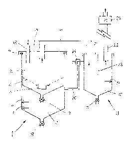
Water separator for continuous separation of water,
air and particles, said separator comprising an inlet
pipe (18) for receipt of a mixture of water, air and
particles simultaneously from several sources such
as dental surgeons etc. an outlet pipe (22) being
connected to a suction motor (23), an upper
chamber (2) being connected with a lower chamber
(3) by a valve (17) in the bottom of the upper
chamber (2), the lower chamber (3) normally being
closed by a check valve (8) in the bottom, a
three-way valve (24) located in an air connection pipe
(20) being adapted to establish a connection
between the upper (2) and lower (3) chambers in a
first position and closing said connection to the
upper chamber and allowing atmospheric air to
enter into the lower chamber (3) in a second
position, and the upper chamber (2) comprising a
coarse filter (4) capturing particles from the liquid
flow to the lower chamber (3), where the water
separator comprises two tanks, a main tank (1) and
a safety tank (11), which are connected through a
connection pipe (19) from the upper chamber (2) in
the main tank (1) to the safety tank (11) and
through the air connection pipe (20) from the tower
chamber (3) in the main tank to the safety tank (11),
that the inlet pipe (18) is through the lid of the main
tank (1), that the outlet pipe (22) is through the lid
or the safety tank (11), and the safety tank (11)
normally being closed by a check valve (15) in the
bottom.
Water separator for continuous separation of water,
air and particles, said separator comprising an inlet
pipe (18) for receipt of a mixture of water, air and
particles simultaneously from several sources such
as dental surgeons etc. an outlet pipe (22) being
connected to a suction motor (23), an upper
chamber (2) being connected with a lower chamber
(3) by a valve (17) in the bottom of the upper
chamber (2), the lower chamber (3) normally being
closed by a check valve (8) in the bottom, a three--way
valve (24) located in an air connection pipe
(20) being adapted to establish a connection
between the upper (2) and lower (3) chambers in a
first position and closing said connection to the
upper chamber and allowing atmospheric air to
enter into the lower chamber (3) in a second
position, and the upper chamber (2) comprising a
coarse filter (4) capturing particles from the liquid
flow to the lower chamber (3), where the water
separator comprises two tanks, a main tank (1) and
a safety tank (11), which are connected through a
connection pipe (19) from the upper chamber (2) in
the main tank (1) to the safety tank (11) and
through the air connection pipe (20) from the lower
chamber (3) in the main tank to the safety tank (11),
that the inlet pipe (18) is through the lid of the main
tank (1), that the outlet pipe (22) is through the lid
of the safety tank (11), and the safety tank (11)
normally being closed by a check valve (15) in the
bottom.
L'invention porte sur un séparateur d'eau destiné à une séparation continue d'eau, d'air et de particules, ledit séparateur comprenant un tuyau d'entrée (18) pour la réception d'un mélange d'eau, d'air et de particules provenant simultanément de diverses sources telles que des chirurgies dentaires, etc., un tuyau de sortie (22) relié à un moteur d'aspiration (23), une chambre supérieure (2) reliée à une chambre inférieure (3) par une soupape (17) dans la partie inférieure de la chambre supérieure (2), la chambre inférieure (3) étant normalement fermée par un clapet anti-retour (8) dans la partie inférieure, une soupape tridirectionnelle (24) située dans un tuyau de raccordement d'air (20) apte à établir une communication entre les chambres supérieure (2) et inférieure (3) dans une première position et fermant ladite communication avec la chambre supérieure et permettant à l'air atmosphérique d'entrer à l'intérieur de la chambre inférieure (3) dans une seconde position, et la chambre supérieure (2) comprenant un filtre grossier (4) capturant les particules provenant de l'écoulement de liquide vers la chambre inférieure (3), le séparateur d'eau comprenant deux réservoirs, un réservoir principal (1) et un réservoir de sécurité (11), qui sont reliés par un tuyau de raccordement (19) entre la chambre supérieure (2) dans le réservoir principal (1) et le réservoir de sécurité (11) et par le tuyau de raccordement d'air (20) entre la chambre inférieure (3) dans le réservoir principal et le réservoir de sécurité (11), le tuyau d'entrée (18) passant à travers le couvercle du réservoir principal (1), le tuyau de sortie (22) passant à travers le couvercle du réservoir de sécurité (11) et le réservoir de sécurité (11) étant normalement fermé dans le fond par un clapet anti-retour (15).
Note: Claims are shown in the official language in which they were submitted.
Note: Descriptions are shown in the official language in which they were submitted.
2024-08-01:As part of the Next Generation Patents (NGP) transition, the Canadian Patents Database (CPD) now contains a more detailed Event History, which replicates the Event Log of our new back-office solution.
Please note that "Inactive:" events refers to events no longer in use in our new back-office solution.
For a clearer understanding of the status of the application/patent presented on this page, the site Disclaimer , as well as the definitions for Patent , Event History , Maintenance Fee and Payment History should be consulted.
| Description | Date |
|---|---|
| Common Representative Appointed | 2019-10-30 |
| Common Representative Appointed | 2019-10-30 |
| Time Limit for Reversal Expired | 2019-09-26 |
| Letter Sent | 2018-09-26 |
| Inactive: Late MF processed | 2018-03-19 |
| Letter Sent | 2017-09-26 |
| Grant by Issuance | 2017-04-18 |
| Inactive: Cover page published | 2017-04-17 |
| Pre-grant | 2017-03-03 |
| Inactive: Final fee received | 2017-03-03 |
| Notice of Allowance is Issued | 2016-09-13 |
| Letter Sent | 2016-09-13 |
| Notice of Allowance is Issued | 2016-09-13 |
| Inactive: QS passed | 2016-09-09 |
| Inactive: Approved for allowance (AFA) | 2016-09-09 |
| Letter Sent | 2016-04-28 |
| Amendment Received - Voluntary Amendment | 2016-04-19 |
| Reinstatement Requirements Deemed Compliant for All Abandonment Reasons | 2016-04-19 |
| Reinstatement Request Received | 2016-04-19 |
| Revocation of Agent Requirements Determined Compliant | 2015-09-21 |
| Inactive: Office letter | 2015-09-21 |
| Inactive: Office letter | 2015-09-21 |
| Appointment of Agent Requirements Determined Compliant | 2015-09-21 |
| Appointment of Agent Request | 2015-09-01 |
| Revocation of Agent Request | 2015-09-01 |
| Inactive: Abandoned - No reply to s.30(2) Rules requisition | 2015-04-29 |
| Inactive: S.30(2) Rules - Examiner requisition | 2014-10-29 |
| Inactive: Report - No QC | 2014-10-23 |
| Letter Sent | 2014-01-29 |
| Letter Sent | 2014-01-29 |
| Request for Examination Received | 2014-01-23 |
| Request for Examination Requirements Determined Compliant | 2014-01-23 |
| All Requirements for Examination Determined Compliant | 2014-01-23 |
| Reinstatement Requirements Deemed Compliant for All Abandonment Reasons | 2014-01-23 |
| Reinstatement Request Received | 2014-01-23 |
| Maintenance Request Received | 2013-12-20 |
| Reinstatement Requirements Deemed Compliant for All Abandonment Reasons | 2013-12-20 |
| Reinstatement Request Received | 2013-12-20 |
| Inactive: Abandon-RFE+Late fee unpaid-Correspondence sent | 2013-09-26 |
| Deemed Abandoned - Failure to Respond to Maintenance Fee Notice | 2013-09-26 |
| Inactive: Delete abandonment | 2011-10-03 |
| Inactive: Cover page published | 2011-05-24 |
| Inactive: Notice - National entry - No RFE | 2011-05-13 |
| Application Received - PCT | 2011-05-11 |
| Inactive: IPC assigned | 2011-05-11 |
| Inactive: IPC assigned | 2011-05-11 |
| Inactive: First IPC assigned | 2011-05-11 |
| National Entry Requirements Determined Compliant | 2011-03-22 |
| Deemed Abandoned - Failure to Respond to Maintenance Fee Notice | 2010-09-27 |
| Application Published (Open to Public Inspection) | 2010-04-01 |
| Abandonment Date | Reason | Reinstatement Date |
|---|---|---|
| 2016-04-19 | ||
| 2014-01-23 | ||
| 2013-12-20 | ||
| 2013-09-26 | ||
| 2010-09-27 |
The last payment was received on 2016-09-20
Note : If the full payment has not been received on or before the date indicated, a further fee may be required which may be one of the following
Patent fees are adjusted on the 1st of January every year. The amounts above are the current amounts if received by December 31 of the current year.
Please refer to the CIPO
Patent Fees
web page to see all current fee amounts.
| Fee Type | Anniversary Year | Due Date | Paid Date |
|---|---|---|---|
| Basic national fee - standard | 2011-03-22 | ||
| MF (application, 2nd anniv.) - standard | 02 | 2010-09-27 | 2011-03-22 |
| MF (application, 3rd anniv.) - standard | 03 | 2011-09-26 | 2011-09-26 |
| MF (application, 4th anniv.) - standard | 04 | 2012-09-26 | 2012-09-05 |
| Reinstatement | 2013-12-20 | ||
| MF (application, 5th anniv.) - standard | 05 | 2013-09-26 | 2013-12-20 |
| Request for examination - standard | 2014-01-23 | ||
| 2014-01-23 | |||
| MF (application, 6th anniv.) - standard | 06 | 2014-09-26 | 2014-09-15 |
| MF (application, 7th anniv.) - standard | 07 | 2015-09-28 | 2015-09-24 |
| Reinstatement | 2016-04-19 | ||
| MF (application, 8th anniv.) - standard | 08 | 2016-09-26 | 2016-09-20 |
| Final fee - standard | 2017-03-03 | ||
| MF (patent, 9th anniv.) - standard | 2017-09-26 | 2018-03-19 | |
| Reversal of deemed expiry | 2017-09-26 | 2018-03-19 |
Note: Records showing the ownership history in alphabetical order.
| Current Owners on Record |
|---|
| FRIDTHJOF MOE |
| Past Owners on Record |
|---|
| None |

