Note: Descriptions are shown in the official language in which they were submitted.
ENGLISH TRANSLATION OF CA 02738202 2011-03-23
ARTICLE 34 AMENDMENTS
DEVICE AND METHOD FOR SERVICE-LIFE MONITORING
[0001] The European Patent Application EP 1 835 149 Al describes a device and
a
method for monitoring the operation of a turbine. For this purpose,
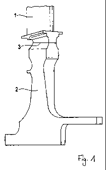
temperature
sensors are used to monitor a component at various locations with respect to
its
tensile stress condition.' The finite method is used to further process the
measured
temperatures into a characteristic quantity in order to describe the tensile
stress
condition.
[0002] The U.S. Patent Application 2004/0148129 Al is concerned with
diagnosing a
damage condition of a stationary power turbine. The diagnostic accuracy is
improved
in that both operating information, as well as process information are
processed
during turbine operation. Operating information is understood to be the
service life, in
particular.
[0003] The present invention relates to a device and a method for monitoring
the
service life of engines or turbines having a compressor blisk and/or a turbine
blisk.
[0004] Aircraft engines and stationary turbines must regularly undergo
maintenance and be examined for any damage that occurred during operation.
This
regular monitoring can be supplemented by a service-life monitoring during
operation
in order to estimate in advance the stress level and the damage condition of
the
engine or the turbine and to facilitate a condition-based maintenance.
[0005] Such an on-board, service-life monitoring of aircraft engines during
operation has been known for quite some time and was developed by the
Applicant
for the RB199 jet engines of the Tornado and EJ200 of the Eurofighter and the
MTR390 turboshaft engine of the Tiger helicopter. This service-life monitoring
employs different algorithms in order to calculate the momentary stresses of
critical
' Translator's note: The published English Abstract of this European Patent
Application has translated
"Span nungssituation" as "voltage situation." In my opinion, it is "tensile
stress condition" that is meant
here, not "voltage situation." Of course, "Spannung" in German can mean both
"voltage" and "stress or
strain," so it is easy to see how this could have been mixed up.
1
ENGLISH TRANSLATION OF CA 02738202 2011-03-23
ARTICLE 34 AMENDMENTS
engine components on the basis of operating parameters that are measured
during
operation of the engine. The accumulated damage to the engine component, that
is
caused by the momentary stresses, is subsequently estimated, and the service
life
that has been consumed to that point is ascertained.
[0006] Compressor blisks and turbine blisks are used in modern engines. The
word 'blisk' is an abbreviated form in English of "blade integrated disk,"
which is
composed of the words 'blade' and 'disk.' As the word indicates, in the case
of one
blisk, the blade and disk form one unit. This eliminates the need for assembly
costs,
and a weight reduction is achieved.
[0007] Blisks can be manufactured by machining the blade profile from the
outer
contour of a forged disk or of a disk segment, or by permanently joining a
blade, for
example, by friction welding, to a disk or a disk segment. The enclosed
drawing
shows a turbine blisk for a high-pressure turbine, where a blade 1 is joined
via a
welded joint 3 to a disk segment 2.
[0008] Depending on the type of engine and the position of the blisk, the
design
of the blisk may also include a supporting segment, which is also referred to
in
English as a "shroud." U.S. Patent 5,562,419 describes an example of a
compressor
blisk that is provided with shrouds.
[0009] It is an object of the present invention to improve the service-life
monitoring during ongoing operation of engines or turbines having a compressor
blisk and/or a turbine blisk.
[0010] In accordance with a first embodiment of the present invention, the
objective is achieved by a device for monitoring the service life of an engine
or of a
turbine having a compressor blisk and/or a turbine blisk, as defined in claim
1. This
device has a read-in device for inputting operating parameters measured during
the
course of engine or turbine operation; a stress calculator for calculating the
momentary stresses of substructures of the blisk on the basis of the measured
2
ENGLISH TRANSLATION OF CA 02738202 2011-03-23
ARTICLE 34 AMENDMENTS
operating parameters; and a damage estimator for estimating the accumulated
damage to the individual blisk substructures caused by the momentary stresses
[the
stress condition at a given instant of time].
[0011] In accordance with a second embodiment of the present invention, a
method for monitoring the service life of an engine or a turbine having a
blisk is
provided, as defined in claim 5. This method includes the steps of measuring
the
operating parameters in the course of engine or turbine operation, calculating
the
momentary stresses of substructures of the blisk on the basis of the measured
operating parameters, and estimating the accumulated damage to the individual
blisk
substructures caused by the momentary stresses.
[0012] The device according to the present invention and the method according
to the present invention are distinguished in that calculations are not only
made of
the momentary stresses of one single critical part of the blisk, but [also] of
at least
two blisk substructures. Moreover, the accumulated damage to the blisk is not
estimated as a single total value; rather, the accumulated damage to the
individual
substructures is estimated. In this manner, it is possible to estimate the
potential
service life of the individual substructures, making possible a substantially
more
accurate estimation of the total service life consumption of the blisk.
[0013] In the case of the present invention, included among the substructures
for
which the momentary stresses are calculated, are preferably at least two of
the
substructures: blade, disk, and, to the extent that it is present, the join
region
between the blade, disk and shroud. These substructures are subject to greatly
varying stress conditions during operation, which is why it is useful to
differentiate
among the individual stress conditions of these substructures and the
individual, thus
associated accumulated damage in these substructures.
[0014] In the case of the present invention, included among the momentary
stress
conditions which are calculated, are preferably at least two of the stress
conditions:
thermomechanical fatigue, creep, low-cycle fatigue, fatigue at high-cycle
fatigue, as
3
ENGLISH TRANSLATION OF CA 02738202 2011-03-23
ARTICLE 34 AMENDMENTS
well as hot-gas corrosion. These stress conditions are the most frequent
failure
mechanisms that limit the service life of the blisk, which is why it is
advisable that
they be taken into consideration when calculating the stress conditions and in
the
subsequent estimation of the accumulated damage.
[0015] Finally, damage tolerances are preferably used when estimating damage.
This generally known concept provides that any damage that occurred during
operation, from which cracks or other defects may arise and which may remain
undiscovered for a defined period of time (for example, until the next
mandatory
scheduled maintenance), be included in the calculation. In other words, a time
buffer
is included in the calculation to ensure that the blisk is never able to reach
the
danger zone.
[0016] In this manner, the present invention makes it possible for the
operating
parameters measured during operation to be used to estimate the accumulated
damage in the individual substructures of the blisk [to enable] an individual
and risk-
minimized utilization of the potential service life of the blisk. This makes
it possible to
improve the planning of maintenance work and to lower operating costs.
Therefore,
the device according to the present invention and the method according to the
present invention are especially suited for developing an optimized
maintenance
strategy, which may include both repairing, as well as replacing the damaged
blisk.
[0017] To illustrate the inventive principle, further details and features of
the
present invention are described in the following.
[0018] In the case of aircraft engines, it turns out that the service life
consumption
and the damage progression are only roughly dependent on the total flight
time.
Thus, in particular, the starting and stopping of the engine and individual
flight
maneuvers, which lead to power peaks during the flight, substantially
influence the
service life of the individual engine components. A change in the control
software or
modification to the hardware of the engine may likewise affect the service
life. For
that reason, it is useful to monitor the service life consumption of the
critical
4
ENGLISH TRANSLATION OF CA 02738202 2011-03-23
ARTICLE 34 AMENDMENTS
components of an engine, for instance, of compressor blisks and turbine
blisks,
during operation.
[0019] Included among the operating parameters of the engine that may be
measured during operation, are, in particular, the intake conditions, the
rotational
speeds, as well as the temperatures and pressures prevailing in the gas
channel and
the cooling-air channels.
[0020] Among the factors that stress the engine components are, first and
foremost, the thermal stresses due to the temperature distribution in the
component,
and mechanical stresses due to the tensile and compressive forces acting on
the
component, but also chemical stresses, such as hot-gas corrosion, for example.
[0021] When calculating the thermal stress, the temperature distribution in
the
component is calculated. Based on the initial temperature distribution, which
is
dependent on the most recent temperature distribution during the previous
operational use, the instantaneous ambient temperature, and the time that has
elapsed since the most recent operational use, the development of the
temperature
distribution is calculated over the entire operational use based on the
measured
operating parameters.
[0022] When calculating the mechanical stresses, the acting total load is
calculated for each monitored region. The total load is composed of thermal
stresses, which are induced by the momentary temperature distribution, the
centrifugal stresses, which are derived from the rotational speed, and of
additional
stresses resulting from the gas pressure, assembly forces, etc.
[0023] Included among the service life-critical substructures of a compressor
disk
or turbine blisk are the blades and the disk or disk segments. Moreover, the
join
region between the blades and the disk may be critical, particularly in the
case of
friction-welded blisks, in the case of which the blades and the disk are made
of
different materials. In the case of blisks having a shroud, damage in the
shroud may
5
ENGLISH TRANSLATION OF CA 02738202 2011-03-23
ARTICLE 34 AMENDMENTS
also limit the service life.
[0024] The stresses acting on the individual substructures of the blisk are
calculated on the basis of special algorithms which are fast enough to permit
an on-
board, real-time calculation. To calculate the stresses acting on the blades,
five
algorithms are preferably used which calculate the thermomechanical fatigue,
creep,
low-cycle fatigue, high-cycle fatigue and hot-gas corrosion, respectively. To
calculate
the stresses acting on the blade and the shroud, two algorithms are preferably
used
in each case which calculate creep and low-cycle fatigue. To calculate the
stresses
acting on the join region between the blade and the disk, two algorithms are
preferably used which calculate the thermomechanical fatigue and the low-cycle
fatigue.
[0025] The stresses, which are calculated for the individual substructures of
the
blisk, are subsequently assessed in terms of the relevant damage mechanism
with
the aid of suitable algorithms in order to estimate on the basis thereof, the
added
damage that occurs in the substructures during operation. This damage is
accumulated with [added to] the already existing damage in the particular
case, so
that an increase in service life consumption may be calculated for each
substructure
relative to the total service life of the substructure.
[0026] The remaining service life of the particular substructure may be
estimated
from the difference between the potential service life and the service life
consumption of the individual substructures. In this context, damage
tolerances are
preferably used to include a time buffer in the calculation, to ensure that
the
accumulated damage of the substructures is never able to reach the danger zone
before the next [scheduled] maintenance. The remaining service life of the
entire
blisk is then determined by the remaining service life of the substructure
having the
highest service life consumption.
[0027] A suitable condition-dependent maintenance strategy may then be
developed as a function of the remaining service lives calculated in this
manner.
6
ENGLISH TRANSLATION OF CA 02738202 2011-03-23
ARTICLE 34 AMENDMENTS
However, if the service-life monitoring of the blisk reveals that the damage
to the
blades is already quite advanced, while the service life consumption of the
disk is not
yet considerable, one possible maintenance strategy could be to replace the
blades
at the end of their remaining service life, however, to continue to use the
disks
following a repair or reconditioning. On the other hand, should it turn out
that the
service-life consumption of the two substructures has advanced to
approximately the
same level, replacing the complete blisk may be the more economical
alternative. In
the first case, following the maintenance, only the accumulated damage of the
blades would be reset to zero, while the remaining substructures retained
their
accumulated damage, whereas, in the second case, the accumulated damage of all
substructures would be reset to zero.
[0028] The result, therefore, is that the service-life monitoring according to
the
present invention renders possible a blisk maintenance that is better suited
for
meeting the requirements and is more cost-effective. Moreover, the data
acquired
from the service-life monitoring may also be used for other purposes, such as
for
further developing the engine or for adapting the engine hardware and engine
software to the individual application prototype of the engine.
[0029] It is understood that the service-life monitoring according to the
present
invention is not only useful for aircraft engines, but also for stationary
turbines, such
as gas turbines, for example, that are not continuously driven at a constant
operating
power. Thus, other possible uses and exemplary embodiments that were not
explicitly addressed may also fall under the scope of protection of the patent
claims.
7