Note: Descriptions are shown in the official language in which they were submitted.
CA 02739635 2013-03-05
Doc. No. 701384 CAD1V Patent
METHOD OF FORMING A RIVET USING A RIVETING APPARATUS
FIELD OF INVENTION
This invention relates to devices and methods for riveting. More specifically,
the
invention relates devices and methods employing rivet forming elements.
DESCRIPTION OF BACKGROUND INFORMATION
There are various techniques for forming a rivet between two pieces of
material. One
such technique includes using a C-shaped yoke with forming tools at opposite
ends of
the yoke. However, after forming many rivets with such a yoke, failure of
various
components of the yoke assembly, such as, the forming tools, occurs and
necessitates
the replacement of the entire yoke. This results in prior art yokes being
expensive and
inefficient since prior art yokes often require replacement, which results in
the expense
of new, replacement yokes, and the halting the riveting process while the
yokes are
being replaced.
U.S. Patent No. 5,771,551 to Schurter etal. discloses one such riveting
device.
SUMMARY OF THE INVENTION
A riveting yoke assembly is provided according to the principles of the
illustrated
embodiment of the present invention including a riveting yoke assembly,
comprising a
yoke having a first end, a second end, and a middle section coupled between
the first
and second ends, the middle section forming an opening between the first and
second
ends; a force applying mechanism coupled to the first end; and a rivet forming
device
coupled to the second end of the yoke, the rivet forming device having a base
end and a
forming end, the base end being attached to the second end of the yoke and the
forming
end having a first recess to form an unformed end of a rivet, the first recess
having a
- 1 -
CA 02739635 2011-05-04
. .
Doc. No. 701384 CADIV
Patent
concave, interior surface, with an annular step positioned between a top edge
of the
interior surface and a bottom-most point of the interior surface.
A riveting yoke assembly is also provided according to the principles of the
illustrated
embodiment of the present invention including a riveting yoke assembly a
riveting yoke
assembly, comprising a yoke having a first end, a second end, and a middle
section
coupled between the first and second ends, the middle section forming an
opening
between the first and second ends; a force applying mechanism coupled to the
first end;
and a rivet forming device removably coupled to the second end of the yoke,
the rivet
forming device having a base end and a forming end, the base end being
removably
attached to the second end of the yoke and the forming end having a recess to
form an
unformed end of a rivet.
A riveting yoke assembly is further provided according to the principles of
the
illustrated embodiment of the present invention including a riveting yoke
assembly a
riveting yoke assembly, comprising a yoke having a first end, a second end,
and a
middle section coupled between the first and second ends, the middle section
forming
an opening between the first and second ends; a force applying mechanism
coupled to
the first end, the force applying mechanism including a shaft movable within
an
aperture in the first end of the yoke; a bushing positioned within said
aperture and
between the shaft and the yoke; and a rivet forming device removably coupled
to the
second end of the yoke, the rivet forming device having a forming end having a
recess
to form an unformed end of a rivet.
Other objects, features and advantages of the illustrated embodiment of the
present
invention will become apparent from the following detailed description, the
accompanying drawings, and the appended claims.
- 2 -
CA 02739635 2011-05-04
Doc. No. 701384 CADIV
Patent
BRIEF DESCRIPTION OF THE DRAWINGS
The illustrated embodiment of the present invention is further described in
the detailed
description which follows, by reference to the noted drawings by way of non-
limiting
exemplary embodiments, in which like reference numerals represent similar
parts
throughout the several views of the drawings, and wherein:
FIG. 1 is an illustration of a riveting system in accordance with one
illustrated
embodiment of the present invention including a perspective view of a riveting
apparatus within a schematic diagram of a riveting system;
FIG. 2 is a perspective view of a riveting yoke assembly shown in FIG. 1;
FIG. 3 is a enlarged side view showing the riveting yoke assembly shown in
FIG. 1,
with a riveted element positioned between first and second rivet forming
devices of the
riveting yoke assembly;
FIG. 4 is a side view showing the riveting yoke assembly shown in FIG.3;
FIG. 5 is a front view of the riveting yoke assembly shown in FIG. 4;
FIG. 6 is a bottom view of the riveting yoke assembly shown in FIG. 4;
FIG. 7 is a side view of the lower rivet forming devices shown in FIG. 3 and
removed
from the yoke;
FIG. 8 is a top view of the second rivet forming device shown in FIG. 7;
FIG. 9 is a cross sectional view taken along line 9-9 in FIG. 7;
FIG. 10 is a top view of a ring for attaching the yoke to a hydraulic
cylinder;
- 3 -
CA 02739635 2011-05-04
Doc. No. 701384 CADIV
Patent
FIG. 11 is a side view of the ring shown in FIG. 10;
FIG. 12 is a functional block diagram of one implementation of the riveting
system
illustrated in FIG. 1;
FIG. 13 is a functional block diagram of another implementation of the
riveting system
illustrated in FIG. 1;
FIG. 14 is a cross-sectional view of the upper and lower rivet forming devices
and
showing the rivet prior to beginning the upset process of securing the rivet
to the
riveted members, with the rivet positioned within an opening of the riveted
members
and the formed end of the rivet positioned within the upper rivet forming
device; and
FIG. 15 is a cross-sectional view similar to FIG. 14 but showing the upper and
lower
rivet forming devices as the rivet is fully formed and secured to the riveted
members.
DETAILED DESCRIPTION OF THE INVENTION
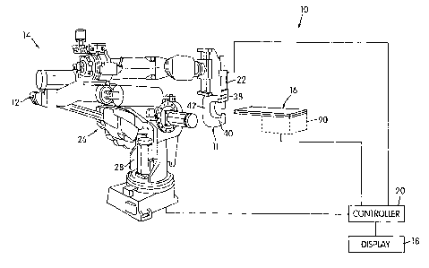
Referring to FIG. 1, in accordance with one illustrated embodiment of the
present
invention, there is provided a riveting system 10 including a rivet yoke
assembly 11
that can be employed by, for example, a riveting apparatus 12 configured to
form rivets
17 in a riveting process, such as in automated manufacturing for coupling
riveted
members 16 together. For example, the riveting apparatus 12 can be employed in
an
automated manufacturing system for a manufacturing line, such as a
manufacturing line
14, as shown in FIG. 1.
The riveting system 10 monitors the forces applied to a rivet 17 by force
applying
mechanisms to determine whether those forces were applied consistent with
predetermined methods and values. If so, the rivet is considered to be
correctly attached
to the riveted members 16. If the force applied to a rivet 17 is not applied
with the
predetermined method and to the predetermined values, that rivet 17 can be
identified
and subjected to further inspection, such as visual inspection. System 10 can
include a
- 4 -
CA 02739635 2011-05-04
Doc. No. 701384 CADIV
Patent
display monitor 18 (FIGS. 1 and 12) or other equipment for displaying the
obtained
rivet quality characteristics to a manufacturing line operator. The yoke
assembly 11 is
designed to have improved performance and enhanced service life. As a modular
system, if a failure occurs within the yoke assembly 11, it does not result in
a complete
replacement of the yoke assembly 11. Thus, the system 10 provides an improved
apparatus and method for riveting.
As shown in FIG. 1, the riveting apparatus 12 may include a force applying
mechanism
such as a hydraulic cylinder 22 coupled to the riveting yoke assembly 11. A
power
supply system such as a hydraulic motor pump assembly 24 (FIG. 12) can be
configured to pump hydraulic fluid into and out from the hydraulic cylinder
22.
The hydraulic motor pump assembly 24, as controlled by the servo valve 86,
provides
pressure and flow of hydraulic fluid required to activate the hydraulic
cylinder 22, i.e.,
move a hydraulic cylinder piston 32 (FIG. 3) certain distances within the
hydraulic
cylinder 22 between an inoperative position (retracted position) and an
operative
position (extended position), for example.
A controller 20 as shown in FIG. 1, connected to the riveting system 10, can
control the
adjustment of the pressure and flow of the hydraulic fluid required to
activate the
hydraulic cylinder 22 via the servo valve 86. The controller 20 can be any
type of
appropriate controller, such as those currently known in the art. For
instance, controller
20 can be a programmable logic controller enabling the controller 20, for
example, to
be programmed to adjust the pressure level within the hydraulic cylinder 22.
FIG. 1 shows the rivet yoke assembly 11 employed by the riveting apparatus 12.
The
riveting apparatus 12 is configured to form rivets, such as rivet 17 joining
riveted
members 16, in a riveting process such as might occur in automated
manufacturing. As
illustrated, the riveting apparatus 12 includes a robot 26 as is generally
known in the art.
The robot 26 is mechanically coupled to the rivet yoke assembly 11 and is
configured
to control positioning and orientation of the rivet yoke assembly 11 via the
controller
20. The control of the robot 26 and the system 10 can be accomplished in a
variety of
- 5 -
CA 02739635 2011-05-04
Doc. No. 701384 CADIV
Patent
ways, such as those illustrated in FIG. 1. Alternatives are also possible as a
robotic
controller (not shown) can be housed in a body 28 of robot 26 or the riveting
apparatus
12 and be configured to control the robot 26 and the system 10, or control the
robot 26
in communication with controller 20. The robot 26 can be any appropriate
robotic
mechanism such as those generally known in the art and can be manually or
automatically controlled, such as, for example, by the robotic controller.
FIGS. 2-6 best show the riveting yoke assembly 11, with FIGS. 4-6 showing a
yoke 30
of the riveting yoke assembly 11 without upper and lower forming devices 34,
36
coupled thereto. The riveting yoke assembly 11 comprises the yoke 30, a force
applying mechanism such as a hydraulic cylinder 22 and the upper and lower
forming
devices 34, 36, respectively. The yoke 30 has a first or upper end 38, a
second or lower
end 40, and a middle section 42 coupled between the first and second ends 38,
40,
respectively. The upper end 38 is disposed in vertical spaced relation with
respect to the
lower end 40 and is positioned generally parallel to the lower end 40. The
first and
second ends 38, 40 cooperate with the middle section 42 to form a generally C-
shaped
configuration, such that an opening 44 is formed through the yoke 30 between
the first
and second ends 38, 40, for receiving the riveted members 16.
The yoke 30 can be made from metal or some other sufficiently rigid material,
for
example, steel such as P-20 1% nickel, or ASTM (American Society for Testing
and
Materials) 2714, which is preferred. In an alternative embodiment (not shown)
the yoke
can be formed into other shapes, which pellnit rivet forming functions.
25 FIGS. 3, 4 and 5 show a plurality of openings 41 extending through the
middle section
42. The openings 41 may be configured to receive fasteners therethrough as
deemed
necessary or desired. For example, fasteners extending through openings 41 can
couple
the middle section 42 of the yoke 30 to other supports or to provide
attachments to the
yoke 30.
- 6 -
CA 02739635 2011-05-04
Doc. No. 701384 CADIV
Patent
The upper forming device 34, as illustrated, is rigidly coupled to the
hydraulic cylinder
piston 32 such that the upper forming device 34 moves with the piston 32 as
the piston
32 moves from its inoperative position to its operative position.
A bushing 64, such as a lined guide bushing, can be positioned within the
upper end 38,
for example, to be level with an upper surface 66 of the upper end 38, as
shown in
FIGS. 3-5. Bushing 64 can be generally cylindrical and can include a step 65
if desired.
Bushings 64 as illustrated in FIG. 3 can extend within the entire extent of
upper end 38.
Bushing 64 is received within an annular aperture 67 in upper end 38 and has
an inner
annular opening 69 for slidingly receiving piston 32. Bushing 64 can be any
appropriate
bushing material but is preferably a plastic bushing such as a RULON lined
guide
bushing. The bushing 64 aligns the cylinder piston 32 and permits easy change-
outs of
the bushing 64 at regular intervals without scrapping an entire yoke 30. For
example,
the bushings 64 could be changed every six months.
As shown in FIG. 3, the hydraulic cylinder 22 is coupled to the upper end 38
of the
yoke 30 by a rivet yoke support ring 68. FIGS. 10 and 11 show a rivet yoke
support
ring 68 in greater detail. FIG. 3 shows the mounting plate 68 interposed
between the
yoke 30 and the hydraulic cylinder 22. The plurality of fastener receiving
openings 60
in the upper end 38 of the yoke 30 align with openings 70 in the mounting
plate 68 such
that fasteners can extend therethrough the aligned openings to releasably
couple the
yoke 30 to the hydraulic cylinder 22. Preferably, each opening has a
countersunk
portion 69 such that the head of a fastener, such as a cap screw, can be
received in the
opening 70. The support ring 68 can extend the life of the bushings 64.
The hydraulic cylinder 22 can be of typical construction, although
appropriately
dimensioned for the specific requirements of the riveting process. Although
the specific
characteristics and features of the cylinder 22 will depend on. the specific
application,
one example of cylinder 22 configuration may include a cylinder operating at
approximately 2800 pounds per square inch of hydraulic pressure with a
cylinder bore
size of 4 inches. Such a configuration can equate to approximately 17 tons of
force
placed on the rivet 17.
- 7 -
CA 02739635 2011-05-04
Doc. No. 701384 CADIV
Patent
The upper forming device 34 can have a base end 43 attached to the hydraulic
cylinder
piston 32. The upper forming device 34 can be threaded on piston 32 or
attached in
other ways. The upper forming device 34 can also have a forming end 45 to
receive a
forming end 210 of rivet 17. Forming end 45 can have a recess 47 shaped to
mate with
the formed end 210 of rivet 17, whatever the shape of the formed end 210 of
the rivet
maybe. As illustrated in FIGS. 14 and 15, the formed end 210 of rivet 17 is
convex, so
the forming end 45 of the upper forming device 34 is concave.
The lower folining device 36 is preferably removably coupled to the lower end
40 of
the yoke 30 yet remains fixed to the lower end 40 during movement of the
hydraulic
cylinder piston 32. The lower forming device 36 has a base 46 end removably
attached
to the lower end 40 of the yoke 30. This attachment with the lower end 40 can
be
accomplished in various ways, for example, the base 46 can be threaded to be
received
with lower end 40 or can be inserted into lower end 40 and then secured by a
threaded
fastener. For example, a fastener could extend through fastener-receiving
opening 61 to
removably couple the lower forming device 36 to the lower end 40 of the yoke
30.
Thus, the lower forming device 36 can be easily removed from the lower end 40
in the
event that the lower forming device must be replaced for any reason, such as,
if the
lower forming device breaks or becomes worn. And this replacement of the lower
forming device 36 can occur without the replacement of the yoke 30, thus
realizing cost
and time savings.
The lower forming device 36 also has a forming end 48 with a recess 50 to form
and
upend a rivet 17. FIGS. 7 and 8 show the lower forming device 36 in greater
detail than
shown in FIG. 3. The lower forming device 36 includes a cylindrical body
portion 76
and an enlarged shank portion 78, which is coupled to the cylindrical body
portion 76.
The cylindrical body portion 76 extends between the enlarged shank portion 78
and the
forming end 48 and has the recess 50 formed therein. The enlarged shank
portion 78
has a beveled surface 79. The shank portion 78 defines a centrally positioned
fastener-
receiving opening 80 therein. FIGS. 3 and 4 best show the base 46 of the lower
forming
device 36 positioned within a seat portion 81 of the lower end 40 of the yoke
30. A
- 8 -
CA 02739635 2011-05-04
Doc. No. 701384 CADIV
Patent
fastener may extend through the opening 61 in the lower end 40 of the yoke 30
and the
fastener-receiving opening 80 to removably fasten the lower forming device 36
to the
yoke 30 when the base 46 is positioned within the seat portion 81. The
fastener-
receiving opening 80 may be threaded, for example, to threadedly engage the
fastener
and to allow easy removal and replacement of the forming device 36 from the
yoke 30.
FIG. 9 shows the forming end 48 and the recess 50 formed in the second forming
device 36 in greater detail than FIGS. 7 and 8. As illustrated, the recess 50
has a
concave, interior surface 52, with the interior surface 52 having an annular
step 54
positioned between a top edge 56 of the interior surface 52 and a bottom-most
point 58
of the interior surface 52. The annular step 54 can be formed in the interior
surface 52
in any known manner, for example, by machining.
The interior surface 52 can be continuous from the top edge 56 to the annular
step 54
and can be continuous from the annular step 54 to the bottom-most portion 58.
The
annular step 54 and the bottom-most portion 58 cooperate to form a circular
depression
57, which is configured to receive a portion of one rivet 17. The
The interior surface 52 can be formed such that the interior surface 52 forms
a first
radius of curvature above the annular step 54 and a second radius of curvature
below
the annular step 54 that is less shallow than the first radius of curvature.
As seen in
FIGS. 14 and 15, the depression 57 below the annular step 54 acts to center
the forming
end of rivet 17 to ensure a proper alignment of the rivet with respect to
riveted
members 16 and to the forming devices 34 and 36 and to the force applied by
the
cylinder 22. Since the depression 57 can guide the rivet 17 straight, the
amount of
improperly fastened rivets 17 can be dramatically reduced.
The rivet 17 can be any type of rivet or any type of force-applied fastener.
As
illustrated, rivet 17 includes a formed portion 210, a middle section 220, and
a formed
end 230. Although the rivet 17 is illustrated as having, for instance, a
convex formed
portion 210, the rivet 17 can be of any appropriate or desired configuration,
depending
in part on the requirements of the bond to be formed by rivet 17.
- 9 -
CA 02739635 2011-05-04
=
Doc. No. 701384 CADIV
Patent
FIG. 12 is a schematic diagram of the riveting system 10. The hydraulic
cylinder 22
and the robot 26 are coupled to the riveting apparatus 12, as described above.
The robot
26 is electrically coupled to the rivet yoke assembly 11 and is configured to
control
positioning and orientation of the rivet yoke assembly 11.
A servo-proportional valve 86 or any other hydraulic servo valve may be
coupled to the
hydraulic motor pump assembly 24 and to the hydraulic cylinder 22 to control
the
hydraulic fluid being pumped through the hydraulic motor pump assembly 24. As
a
result, the servo-proportional valve 86 can control the speed and distance of
the
hydraulic cylinder piston 32. As best seen in FIG. 12, a pressure transducer
88 is
coupled to an inlet 89 of the hydraulic motor pump assembly 24 and is
configured to
provide feedback to the controller 20, such as a pressure signal representing
a hydraulic
fluid pressure exerted on the hydraulic cylinder piston 32. The amount of
pressure to be
exerted could be set so that the output of the pump assembly 24 outputs the
desired
pressure.
The controller 20, for example, could operate the servo-proportional valve 86
to extend
or retract the piston 32, which in turn, extends or retracts the first forming
device 34
based on algorithms, for example. The algorithms may produce "axis motion
profiles"
based upon the position of the piston 32 versus pressure measured at the inlet
89 of the
hydraulic cylinder 22. The "axis motion profiles" represent comparison data
generated
from the position and pressure signals obtained from the linear transducer 84
and the
pressure transducer 88, respectively. The "axis motion profiles" are used to
determine
the linear position of the piston 32 as well as to maintain a desired pressure
at the inlet
89 of the hydraulic cylinder 22.
The controller 20 can perform the comparison of the linear transducer 84 and
the
pressure transducer 88, which is represented in FIG. 12 by reference numeral
91. The
"axis motion profiles" can be outputted to the servo-proportional valve 86
based upon
desired performance, e.g., programmable values of the controller 20, to extend
or
retract the piston 32.
- 10-
CA 02739635 2011-05-04
Doc. No. 701384 CADIV
Patent
During the advance stroke or extension of the piston 32, the controller 20
monitors the
pressure via a pressure signal from the pressure transducer 88. The cylinder
20
preferably operates at low pressure until the upper forming device 34 contacts
the rivet
surface 210 at which point, the profile shifts to its pressure cycle and
completes the
compression of the rivet 17. The pressure values measured at the inlet 87 of
the
hydraulic cylinder 22 are continuously monitored and are constantly compared
to the
linear values representing the position of the piston 32 that are outputted
from the linear
transducer 84. The pressure and position signals outputted from the linear
transducer 84
and the pressure transducer 88, respectively, can either be analog or digital
signals that
can be transmitted over a wired or wireless network, for example.
The controller 20 can be configured to detect certain faults within the
riveting system
10, such as, for example, high pressures, out of linear limits and loss of
feedback
signals. For example, if the pressure measured at the inlet 87 builds up too
early (is too
high) when compared to the piston position, then the rivet to be riveted could
be too
long and if the pressure measured at the inlet 87 builds up to late (is too
low) when
compared to the piston position, then the rivet to be riveted could be too
short, for
example. The controller 20 also monitors the final riveted product, such as an
automotive chassis, to ensure that all the parts being riveted together are
present. If a
defect occurs, the controller 20 can track the defective rivet through the
riveting process.
A manual inspector, for example, could inspect rivet data of the defective
rivets on the
display 18, as discussed above.
A controlled "axis motion profile" can be configured to prohibit the hydraulic
piston 32
from filly extending, for example, if an obstruction is present between the
rivet 17 and
one or both of the first and second forming devices 34, 36.
A frame control system 90 may be coupled to the controller 20 and may be
controlled
by the controller 20. The frame control system 90 is configured to control
positioning
and orientation of a frame 92, such as an automobile chassis, that is to be
riveted during
a riveting process. The frame control system 90 may include both hardware and
- 11-
CA 02739635 2011-05-04
Doc. No. 701384 CADIV
Patent
software to monitor and position the frame 92 into proper placement to be
riveted by
the riveting apparatus 12, for example, using manufacturing line 14 shown in
FIG. 1.
If the riveting system ascertains that a rivet under inspection does not meet
a
predetermined standard, a mechanical diverter (not shown) or some other
controllable
device, connected to the riveting system 10 can be signaled to remove a faulty
rivet (not
shown) from the line 14 when the faulty rivet is conveyed to the location of
the diverter.
The diverter can move the faulty rivet off the line 14 and into, e.g., a
storage receptor
(not shown) for rejected rivets.
FIG. 13 is a flow chart showing a method of using the riveting system shown in
FIG. I.
The method begins at 300. At 302, a riveting apparatus, such as the riveting
apparatus
12, is provided. The riveting apparatus has a force applying mechanism, such
as a
piston 32 within a hydraulic cylinder 22, and a forming assembly, such as
upper and
lower forming devices 34, 36. The force applying mechanism and the forming
assembly are constructed and arranged to form rivets, such as rivet 17, for
example.
At 304, a pressure signal representing a pressure in the riveting apparatus is
obtained
and a position signal representing a position of the force applying mechanism,
e.g., the
linear travel of the piston 32 within the hydraulic cylinder 22 is obtained.
The linear
travel of the piston 32 includes travel to its operative or extended position
from its
inoperative or retracted position.
At 308, the pressure signal and the position signal are compared, for example,
by the
controller 20 (FIG. 12). At 310, comparison data is generated from the
pressure signal
and the position signal. At 312, the riveting apparatus is controlled, for
example, by a
controller and a microprocessor, for example, to effect a riveting action
which forms
rivets based at least in part on the comparison data.
Hence, it is within the principles of the present invention for the riveting
system 10 to
be operated to manually form rivets (as illustrated shown in relation to FIG.
13) or to be
- 12 -
CA 02739635 2013-03-05
Doc No 701384 CADIV Patent
operated in an automated fashion, either in fill or in part, to form rivets
(as illustrated in
relation to FIG. 1).
It should be understood that the riveting system 10 can be implemented, for
example, as
portions of a suitably programmed general-purpose computer. It should also be
understood that the system may be implemented, for example, as physically
distinct
hardware circuits within an system. For example, although the system 10 has
been
described as a general-purpose computer, for example, a personal computer, it
is
foreseeable that the system 10 may be a special purpose embedded processor.
The above-described embodiments are intended to be examples of the present
invention.
Numerous other embodiments may be envisaged without departing from the scope
of
the instant invention.
- 13-