Note: Descriptions are shown in the official language in which they were submitted.
CA 02739874 2011-04-06
WO 2010/041006 PCT/GB2009/002393
-1-
Speed Responsive Engagement Device
This invention relates to a speed responsive engagement device, and in
particularly to a
speed responsive engagement device for use in fall arrest apparatus.
Speed responsive engagement devices for use with rotating parts to selectively
engage the
rotating parts to other components if the speed of rotation of the parts
exceeds a threshold
value are well known.
There are two main types of such speed responsive engagement devices. A first
type of
speed responsive engagement device is of the centrifugal clutch type. Such an
arrangement is described in figure 1 of W02008/007119.
A second type of speed responsive engagement device is of the rocking pawl
type. An
exemplary embodiment of a ratchet and pawl speed responsive engagement device
is
disclosed in, for example W02008/007119.
The speed sensitive engagement means of both of these known types are used in
fall arrest
systems of the type where personnel working at height are attached to a safety
line wound
around a drum. The drum has an automatic rewinding mechanism and a speed
sensitive
attachment mechanism of the type disclosed above, which responds to the
rotation of the
drum at a speed above a predetermined threshold by holding the drum against
further
rotation relative to the drum support or other fixed structure.
In use, fall arrest systems of this type allow personnel to move freely around
a working
area including moving upwardly and downwardly in the area, with the safety
line being
automatically paid out from and wound onto the drum under the control of the
automatic
rewinding mechanism as necessary to allow the personnel movement and keep the
safety
line taut. When a personnel fall occurs, the safety line is pulled out at a
much greater speed
then is necessary for normal movement and the speed of rotation of the drum
rises to the
threshold value of the speed sensitive engagement means, which brakes the drum
against
further rotation and so arrests the fall.
CA 02739874 2011-04-06
WO 2010/041006 PCT/GB2009/002393
-2-
In practice it has been found that there is a problem with fall arrest systems
of both of these
known types that after a fall has been arrested the speed sensitive engagement
means can
release the engagement allowing the personnel to again start to fall until the
speed of
rotation of the drum again reaches the threshold value and the fall is again
arrested.
It has been found that it is possible for this cycle to be repeated so that
personnel drop. in a
series of short falls until they reach the ground or some other supporting
surface.
This problem is generally referred to as bounce. The problem of bounce is
caused by the
fact that when the known speed sensitive engagement means are in the engaged
state the
pawls are biased into a unengaged condition and are only kept in the engaged
condition by
the pawls being held against the biasing by the ratchet teeth. When these
engagement
means are used in a fall arrest system and a fall arrest occurs there is a
stretching or
tensioning of the safety line followed by a momentary reduction in tension to
zero as the
arrested person bounces at the end of the safety line. During this momentary
reduction in
tension the automatic rewinding mechanism causes the drum to rotate slightly
in the
rewinding direction, releasing the pawls from engagement with the ratchet
teeth. The
biasing then causes the pawls to move to the unengaged position, releasing the
drum and
allowing the personnel to start falling again.
Bounce is dangerous and presents a serious problem for a number of reasons.
Firstly, the
personnel may be injured by impact with other objects during the multiple
falls. Further, in
general fall arrest systems are designed so that users undergoing a fall
arrest event are only
subject to a safe level of force. However, these safe levels are calculated on
the assumption
of single fall event. Even when a single application of a fall arrest force is
safe, repeated
application of the same force to a user can result in injury. This problem is
made more
severe by the fact that many fall arrest systems include single use energy
absorbing or
shock limiting devices so that successive falls and arrests resulting from
bounce may result
in personnel being subject to higher than expected levels of force because the
capacity of
the single use energy absorbing or shock limiting devices in the system has
been used up.
Further, the repeated fall and arrest loads on the fall arrest system due to
bounce can result
in failure or damage of components of the fall arrest system or the supporting
structure to
which it is attached. Finally, where bounce results in personnel descending
all the way to
CA 02739874 2011-04-06
WO 2010/041006 PCT/GB2009/002393
-3-
the ground or other supporting structure in a series of short falls the final
impact with the
ground or other support structure may be at a sufficiently high speed to cause
injury. The
bounce problem is addressed by the arrangement disclosed in W02008/007119.
Control over the way in which the pawl moves from the engaged position to the
disengaged position when the ratchet and pawl rotate relative to one another
in the reverse
direction is important in controlling the effect of bounce. In particular
manufacturing
tolerances of components in the arrangement can have an effect upon the
circumstances of
such operation. The present invention provides an arrangement in which the
operation of
the pawl to be held in the engagement position and caused to move from the
engaged
position to the disengaged position is more accurately controlled.
In accordance with the present invention, there is provided a speed responsive
engagement
device comprising:
a ratchet wheel having a plurality of outwardly projecting spaced apart teeth;
a pawl arranged for pivotal movement about an axis between an engagement
orientation in which the pawl is orientated for braking engagement with one or
more of said ratchet wheel teeth, and a disengagement orientation in which the
pawl is pivoted away from the engagement orientation; the pawl and the ratchet
wheel being rotatable relative to one another such that when relative rotation
occurs between the ratchet wheel and the pawl in a first direction the pawl
contacts the ratchet wheel, generating an oscillating movement of the pawl
with
an amplitude dependent on the speed of the rotation, and when the speed of
rotation reaches a predetermined value the increased oscillating movement
causes
the pawl to move into the engaged orientation brakingly engage with the
ratchet
wheel teeth preventing further relative rotation between the ratchet wheel and
the
pawl in the first direction;
a resilient biasing arrangement arranged to bias the pawl towards the
disengaged
orientation; and
CA 02739874 2011-04-06
WO 2010/041006 PCT/GB2009/002393
-4-
a capture arrangement arranged to capture the pawl in the engaged orientation
when the pawl is brakingly engaged with the ratchet wheel.
In a speed sensitive engagement according to the present invention the biasing
arrangement
(typically a leaf spring) can be set to preferentially bias the pawls
constantly to the
disengaged state and therefore the tolerances for setting the biasing
arrangement are
greater. The capture arrangement only acts to detain the pawl in the
engagement
orientation when the pawl has moved by the rotational speed threshold having
been
reached. The pawl is only released from the capture arrangement, not by action
of any
biasing means, but by some other physical means such as the reverse
oscillation of the
pawl as relative movement occurs between the pawl and the ratchet wheel in the
second
direction of rotation (the rewinding direction). The pawl is not biased when
in the engaged
state contacting the circumferential surface and the small rotation of the
drum in the
rewinding direction will not be sufficient to move the pawls to the end of the
circumferential surface and cause movement of the pawl from the engaged state
to the
unengaged state and release from the capture arrangement.
It is preferred that the pawl comprises a heel portion and the capture
arrangement is
arranged to hold the heel portion of the pawl captive. Beneficially, the heel
portion of the
pawl contacts a peripheral surface of the ratchet wheel generating the
oscillating movement
of the pawl as relative rotation occurs between the ratchet wheel and the pawl
in a first
direction. The underside of the heel portion typically rides over the
peripheral surface of
the ratchet wheel teeth in order to effect the oscillating motion of the pawl
as relative
rotation occurs.
The pawl is typically spaced from the capture arrangement in normal operation
as the
ratchet wheel and pawl rotate relative to one another. The pawl preferably
remains free
from the capture arrangement until the pawl pivots to brakingly engage the
ratchet wheel.
Beneficially the pawl is arranged to be released from the capture arrangement
by relative
rotation of the ratchet wheel and the pawl in a second direction (rewinding
direction)
opposite to the first rotation direction (paying out direction).
CA 02739874 2011-04-06
WO 2010/041006 PCT/GB2009/002393
-5-
In a preferred embodiment the pawl includes a toe portion to brakingly engage
the ratchet
wheel teeth and a heel portion to be held captive by the capture arrangement
and wherein
upon relative rotation in the second direction (rewinding direction), the toe
portion of the
pawl rides over the periphery of the ratchet wheel causing the heel portion of
the pawl to
pivot out of captive engagement with the capture arrangement.
As mentioned previously, it is preferred that, in both the engagement
orientation in and the
disengagement orientation, the resilient biasing arrangement acts to bias the
pawl in favour
of the disengaged orientation.
In a preferred embodiment the capture arrangement comprises a detent.
Beneficially the
detent comprises a resilient element (such as a resiliently deflectable arm)
able to deflect to
and from a normal orientation in order to capture the pawl. It is preferred
that the resilient
element is caused to deflect to capture the pawl as the pawl moves to the
engagement
position to brakingly engage the ratchet wheel.
In a preferred embodiment, the pawl and the detent include complementary
engaging
formations arranged to engage when the pawl is held captive by the capture
arrangement.
One of the formations may beneficially comprise a notch in the heel of the
pawl.
As mentioned previously, the resilient biasing arrangement preferably
comprises a spring
element.
In one embodiment, adjacent ratchet wheel teeth are separated by a
circumferential surface
of the ratchet wheel having a substantially constant radius.
It is preferred that the capture arrangement is arranged to detain the pawl
against
movement in both opposed pivotal directions away from the engagement
orientation.
Beneficially, the ratchet wheel teeth have an undercut surface arranged to
urge the pawl
into the engaged position.
CA 02739874 2011-04-06
WO 2010/041006 PCT/GB2009/002393
-6-
It is preferred that the pawl oscillates in contact with the ratchet wheel in
normal when the
wheel rotates in either or both directions generating an audible sound.
Beneficially, the arrangement includes a plurality of pawls.
In a preferred realisation the invention comprises a fall arrest device
comprising a speed
responsive engagement device as described herein together with an elongate
supporting
means wound around a drum, the speed responsive engagement device being
arranged to
respond to rotation of the drum in a direction unwinding (paying out) the
elongate support
means.
Preferred embodiments of the invention will now be described by way of example
only
with reference to the accompanying diagrammatic figures, in which:
Figures 1 is a schematic side view of a fall arrest safety system
incorporating a speed
responsive engagement device according to the invention;
Figures 2 to 4 are schematic side views of the arrangement of figure 1 in
progressive
sequential orientations positions during normal unwinding (paying out)
rotational
orientation;
Figure 5 is a schematic side view similar to the view of figures 1 to 4 with
the pawl of the
speed responsive engagement device orientated to the braking engagement
position with
respect to the ratchet wheel;
Figures 6 to 8 are schematic side views of the arrangement of the preceding
progressive
sequential orientations positions during rewinding following the braking
engagement
situation as shown in figure 5;
Figure 9 is an end view of the fall arrest safety system of the preceding
figures;
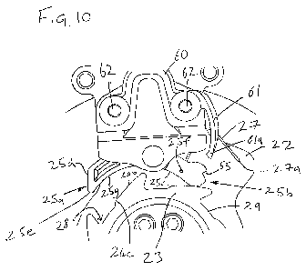
Figure 10 is a close up view of the orientation of figure 8.
CA 02739874 2011-04-06
WO 2010/041006 PCT/GB2009/002393
-7-
Referring initially to figures 1, 2 and 9, a fall arrest system 1 includes a
speed responsive
arrangement arranged to control rotation of a drum 40 around which a safety
line (not
shown) is wound. The speed sensitive arrangement comprises a toothed ratchet
wheel 23
(which is mounted on a shaft 21 to rotate with the drum 40) and a pair of
pawls 25 which
are arranged at diametrically opposed positions on either side of the ratchet
wheel 23 .
Only one of the pawls 25 is shown in the drawings. A pair of pawls 25 is used
to improve
safety; the system could however function with only one pawl. The pawls 25 are
each
capable of independently stopping rotation of the ratchet wheel 23 and drum
40. The
pawls 25 are pivotally mounted and do not rotate with the ratchet wheel 23.
The drum 40 is mounted for rotation between a pair of sideplates 42a and 42b.
The speed
sensitive arrangement is located between one of the sideplates 42a and a
further sideplate
42c arranged parallel to the sideplate 42a and secured to the sideplate 42a by
a pair of
endwalls 42d. The pawls 25 are mounted on pivot bosses 52 for pivotal movement
between
the sideplates 42a and 42c. The mounting of the pawls 25 between the two
sideplates 42a
and 42c helps to stabilise the pawls 25.
Referring to figures 2 and 3, the operating parts of the speed responsive
engagement
arrangement according to the present invention are shown. The arrangement is
responsive
to the speed of rotation in a clockwise direction of the drum (and hence
responsive to the
speed of rotation of the shaft 21 and the ratchet wheel 23) relative to a
fixed support
structure of the safety apparatus (i.e. the sideplates 42a 42c).
The ratchet wheel 23 mounted on the shaft 21 comprises a circumferential
surface 29 and a
plurality of identical teeth 24 arranged evenly spaced around and projecting
outwardly
from the circumferential surface 29. Each tooth 24 has an undercut inner front
sloping
surface 24a and an outer rear sloping surface 24b (see figure 4). The teeth 24
are shaped
and spaced to leave a section of the circumferential surface 29 of the wheel
23 between
adjacent teeth 24. The outer rear sloping surface 24b of each tooth 24 ends in
a step 24c
down to the circumferential surface 29.The inner front sloping surface 24a of
each tooth 24
is arranged to define a recess 28 between the front surface 24a and the
circumferential
surface 29 of the wheel 23.
CA 02739874 2011-04-06
WO 2010/041006 PCT/GB2009/002393
-8-
The pawl25 is mounted for pivotal movement about an axis on pivot boss 52 on
the
supporting structure adjacent to the ratchet wheel 23. The pawl 25 can move in
a first
oscillating regime in a disengaged manner, shown in figure s 1 to 4, in which
the ratchet
wheel 23 and shaft 21 are able rotate relative to the fixed structure 22. As
will be
described later rotation of the shaft and drum above a predetermined threshold
speed
causes the pawl to pivot to an extreme pivoted orientation (engagement
orientation) in
which the toe of the pawl brakingly engages with the ratchet wheel 23 so that
rotation of
the ratchet wheel 23 and shaft 21 relative to the support structure 22 (and
pawl 25) in a
clockwise direction is prevented. This is the braking engagement orientation
as shown in
figure 5.
The engagement between the pawl 25 and ratchet wheel 23 only prevents rotation
of the
shaft 21 in one direction, clockwise in the figures. Similarly to the prior
art devices rotation
of the shaft 21 in the opposite direction, anticlockwise in the illustrated
embodiment,
releases the engagement between pawl 25 and ratchet wheel 23. The speed
responsive
engagement device according to the present invention could be made opposite
handed to
be responsive to rotation in an anticlockwise direction.
The pawl 25 (as most clearly shown in figure 10) is arranged for pivoting
movement
around the axis of pivot formation 52 and has a toe end 25a and a heel end 25b
arranged on
opposite sides of the pivot axis. The toe end 25a of the pawl 25 is shaped to
be able to
engage with a tooth 24 of the ratchet wheel 23 when the pawl 25 is in the
braking engaged
position, as shown in figure 5. The lower side of the pawl between the toe and
the heel 25b
has a smoothly curved concave inner surface 25c so that when the pawl 25 is in
the
disengaged position shown in figure s 1 to 4 and the ratchet wheel 23 rotates
in a clockwise
direction underside of the pawl is contacted by a tip of each tooth 24 of the
ratchet wheel
23 so that as the ratchet wheel 23 rotates the second end 25b of the pawl 25
is urged
outwardly.
Also as shown most clearly in figure 10, a leafspring 27 connects a point 27a
on the fixed
structure 22 to a point 25f on the pawl 25. The leafspring 27 is held in
compression so that
it permanently preferentially urges the pawl 25 to rotate clockwise towards
the disengaged
position shown in figure 10. The clockwise rotation of the pawl 25 driven by
the leafspring
CA 02739874 2011-04-06
WO 2010/041006 PCT/GB2009/002393
-9-
27 is limited by the heel 25b of the pawl 25 contacting a tooth 24 of the
ratchet wheel 23.
The heel 25b is provided with a v shaped notch 55, the purpose of which is
explained later.
Accordingly, when the shaft 21 and the attached ratchet wheel 23 rotates
clockwise under
normal operation, each tooth 24 of the ratchet wheel 23 in turn contacts the
heel 25b of the
pawl 25 and urges the heel 25b of the pawl 25 outward against the bias of the
leaf spring
27. As a result, the pawl 25 follows an oscillating movement as shown in
figures 1 to 4.
The higher the speed of relative rotation of the shaft 21 and ratchet wheel
23, the greater
the amplitude of the oscillation of the pawl 25 will be. When the speed of
clockwise
rotation of the shaft 21 and ratchet wheel 23 rises to a threshold speed the
amplitude of the
oscillation of the pawl 25 will be sufficient to pivot the pawl 25 to its
extreme position, to
bring the toe end 25a of the pawl 25 into contact with a tooth 24 of the
ratchet wheel 23.
The braking engagement position as shown in figure 5.
When the pawl 25 is in the disengaged position and the ratchet wheel 23
rotates
anticlockwise (rewinding in the line on the drum 40) the heel 25b of the pawl
25 is
contacted by the outer surface of each tooth 24 of the ratchet wheel 23 so
that as the ratchet
wheel 23 rotates the heel 25b of the pawl 25 is urged outward against the bias
of the leaf
spring 27. As a result, the pawl 25 follows an oscillating movement out of the
unengaged
position shown in figure 3 towards the engaged position shown in figure 4 and
then back to
the unengaged position shown in figure 3. The toe end 25a of the pawl 25 has a
smoothly
curved concave inner surface 25g.
As explained above, rotation of the shaft 21 and ratchet wheel 23 in either
direction causes
contact of each tooth 24 in turn with the pawl 25. These contacts produce a
clicking sound
which provides an audible indication of proper operation of the engagement
device 20 to a
user.
The toe end 25a of the pawl 25 has an outer end surface 25d shaped to
cooperate with the
front surface 24a of the tooth 24 so that when the end outer end surface 25d
contacts front
surface 24a of a tooth 24 the first end 25a of the pawl 24 is urged into the
recess 28. As a
result, when the speed of rotation of the shaft 21 and ratchet wheel 23 rises
to the threshold
CA 02739874 2011-04-06
WO 2010/041006 PCT/GB2009/002393
-10-
value the pawl 25 will be pivoted into the engaged position shown in figure 5
where a tip
25e of the first end 25a of the pawl 25 is inserted as far as possible into
the recess 28 and
contacts the front surface 24a of the tooth 24 and the circumferential surface
29 of the
wheel 23, which extends between the teeth 24. This engagement will brake the
ratchet
wheel 23 against the pawl 25 and stop further clockwise rotation of the shaft
21 and ratchet
wheel 23 relative to the fixed structure 22.
As this reorientation of the pawl 25to the engaged position occurs, the heel
25b of the pawl
is captured by a capture arrangement 60 comprising a resiliently flexible
detent arm 61.
The capture arrangement is fixed to the structure plate 42d by means of
fasteners 62, and
the detent arm 61 extends from a fixed end to a free end 61 a which is
provided with a male
formation for engagement in the v shaped notch formed in the heel 25b of the
pawl 25.
The detent arm flexes as the heel 25b passes by the free end of the arm. Then
the heel is
captured by the capture arrangement as shown in figure 5, the leaf spring 27
still acts to
promote reorientation of the pawl 25 to the disengaged position but movement
of the pawl
to revert to the disengaged position is prevented by engagement with the tooth
recess 28
and also the location of the detent arm 61 of the capture arrangement 60.
If bounce occurs (or when the line is deliberately re wound) causing movement
of the
ratchet wheel in the anticlockwise direction, the tip 25e of the pawl toe end
25a rides along
the constant radius surface until the step formation 24c is reached. Up until
this point the
pawl remains in the engagement orientation even though the tip 25e of the toe
end 25a of
the pawl 25 is no longer located fast in the tooth recess 28. This is because
the heel end
25b of the pawl 25 remains held captive by the detent of the capture device.
During
bounce, this degree of anticlockwise rotation is not surpassed and therefore
during a fall
event, once the pawl is pivoted to the engagement orientation to engage the
teeth, it is not
subsequently moved back to the disengaged position.
In other situations where for example the pawl 25 is pivoted to the engaged
situation, then
allowing the line to be rewound (in the anticlockwise direction of rotation of
the ratchet
wheel) causes the tip 25g of the toe end 25a of the pawl 25 to reach the step
25c (figure 6)
and then pass up along the outer surface 24b of a tooth 24 (figure 7). In so
doing the pawl
is caused to pivot about the pivot formation 45 and the heel 25b of the pawl
is released
CA 02739874 2011-04-06
WO 2010/041006 PCT/GB2009/002393
-11-
from being held captive by the detent arm 61 of the capture arrangement. The
pawl is then
urged back to the disengagement orientation by the leaf spring 27 (figure 8).
The surface profile of the ratchet wheel between adjacent teeth 24 sets a
threshold amount
of counter rotation (anticlockwise in the embodiment) required to disengage
the pawl 23
from a tooth 24. Counter rotation by less than this threshold amount will not
disengage the
pawl 23 from a tooth 24. The counter rotation causes the pawl to be pivoted by
reaction
against the ratchet wheel to be released from the capture arrangement. The
constant
biasing to restore the pawl to the disengaged position is free to act to move
the pawl 25
once the pawl has been released from the capture arrangement 60.
As a result, when the speed responsive engagement device 20 of the present
invention is
used in a fall arrest system, if a fall causes a safety line to be unwound
from a drum at or
above the threshold speed the pawl 25 will engage with a tooth 24 of the wheel
23,
stopping the rotation of the drum and arresting the fall. If the tension in
the safety line then
temporarily drops to a low value or zero because of the arrested person
bouncing on the
end of the safety line, or other transient effects, the resulting small
anticlockwise rotation
of the wheel 23 produced by the automatic rewinding mechanism will not
disengage the
pawl 23 from the tooth 24 and allow the person to resume their fall.
Accordingly, the
problem of bounce is overcome.
In the descriptions of the preferred embodiment set out above the use of a
safety line
wound around the drum is referred to. This is not essential and other forms of
elongate
support such as a cable or a webbing strap could be used instead.
In the embodiment described, the ratchet wheel is rotatable with respect to
the support
surface 22 and side plates 42a, 42c. In an alternative embodiment the ratchet
wheel could
be fixed and the pawls 25 mounted for rotation with the drum 40.
The above description refers to fall arrest systems for arresting a fall by a
user. This is the
most common application of a fall arrest system. However, the present
invention can also
be used in a height safety system to arrest falls by objects, for example,
equipment being
used or moved at height.
CA 02739874 2011-04-06
WO 2010/041006 PCT/GB2009/002393
-12-
The embodiments discussed above are examples only and are not exhaustive. The
skilled
person will be able to envisage further alternatives within the scope of the
present
invention as defined by the attached claims.