Note: Descriptions are shown in the official language in which they were submitted.
CA 02739996 2011-04-08
WO 2010/040802 PCT/EP2009/063094
1
A METHOD OF PROCESSING FISH AND A FISH PROCESSING PLANT
The present invention relates to a method and a system for processing fish, in
particular sardines.
In the foodstuffs industry there is a need for automated processes for
separating the non-consumable end waste parts of the fish from the
consumable body part of the fish. The end waste parts may constitute the
head, gills and tail of the fish. The present invention seeks to provide a
system
and a method for the above task.
Previous technologies, such as e.g. US 4,551,885, typically provide a conveyer
belt where the fish is placed in a specific position. Such specific position
is
typically determined by arranging the fish into a standardized compartment
substantially corresponding to the anatomy of a standard fish or simply by
arranging the fish against a fixed object, such as the wall or side of the
conveyer belt. The conveyer belt transports the fish towards a fixed knife
arrangement placed in a position suitable for decapitating a standard fish for
which the arrangement was designed. The knife arrangement divides the fish
into a head and gills part and a body part, where the tail belongs to the body
part.
The drawback of the arrangement described above is evident, since it
presumes that all fish to be processed are having exactly the same anatomy.
However, even within a species of fish the size and in particular the position
of
the gills will differ significantly. To ensure no part of the head or gills
remains
with the body of the fish after decapitation, a substantial safety margin must
be
used when determining the position of the knife to allow for anatomic
variations
of the fish. The margin constitutes a loss since the meat remaining with the
head and gills part of the fish after decapitation cannot be further processed
and must be disposed or sold at a considerable lower price than the price of
the
meat in the body part of the fish. It has been estimated that in average
approximately 10% of valuable fish meat remains with the head and gills part
of
CA 02739996 2011-04-08
WO 2010/040802 PCT/EP2009/063094
2
the fish, since according to the fish anatomy the thickest part of the fish
body
and thereby the most meat is located near the gills. Consequently, even using
a relatively small margin a relatively large amount of meat will be lost for
further
processing.
It would therefore be beneficial to have a process where each specific fish is
cut in an optimal position in respect to the position of the gills of each
specific
fish. It is, however, very difficult to identify the position of the gills by
an
automatic process due to the smooth surface of the fish.
It is, therefore, an object according to the present invention to provide a
method
and a system for automatically removing the end waste part, such as head,
gills
and tail, of different fish anatomies in an optimal and efficient way for each
fish,
and thereby minimize the loss of valuable fish meat in the fish body.
The above need and the above object together with numerous other objects
and features will be evident from the below detailed description of an system
according to a first aspect of the present invention for processing fish of a
single species and of different anatomic constitution having at least an end
waste part, a body part and a transition between the end waste part and the
body part, the system comprising:
a frame, defining a first end and a second end opposite the first
end and including a fish loading area for receiving the fish at the first end
and a
fish unloading area at the second end,
an optical measurement unit located at the first end monitoring at
least part of the fish loading area for producing a digital representation of
the
fish,
a grabbing unit mounted on the frame downstream in relation to
the optical measurement unit between the first end and the second end for
collecting the fish from the fish loading area and placing the fish on the
fish
unloading area,
a processing unit for receiving the digital representation of the
CA 02739996 2011-04-08
WO 2010/040802 PCT/EP2009/063094
3
fish, determining the transition between the end waste part and the body part
of
the fish and controlling the grabbing unit, and
a separation arrangement located at or downstream in relation to
the grabbing unit for separating the end waste part from the body part at the
transition.
In the present context it has surprisingly been found out that by using modern
computer technologies, robotics and digital camera technologies it would be
possible to create the digital representation of the fish, calculate the
optimal
position for the transition between the end waste part and the body part of
the
fish and by using the grabbing unit manipulate the fish into the position
where
the fish may be separated into the end waste part and the body part by the
separation arrangement. In the present context it may be contemplated that the
end waste past may constitute a multitude of undesired parts of the fish, such
as the head, tail, fin, gills etc. The optimal position for the transition
between
the head part and the body part in the present case is the position where the
complete gills but no substantial amount of meat belongs to the head part.
Consequently, the transition between the tail part and the body part may be
calculated as the position where the complete tail, but no substantial amount
of
meat belongs to the tail part. It may be further contemplated that the body
part
of the fish may as well constitute a multitude of valuable meat parts of the
fish,
and that it in some circumstances may be advantageous to separate the body
part into a multitude of meat parts.
The optimal position for the separation is determined from the digital
representation by the use of the computer processor and suitable image
processing software. The optimal position may preferably be determined in
relation to a predefined coordinate system.
For the digital representation to be suitable for further processing by the
computer processor and the image processing software, the fish should be
placed at the loading area in a single layer having at least some amount of
space between each fish.
CA 02739996 2011-04-08
WO 2010/040802 PCT/EP2009/063094
4
To achieve the above requirement in an automatic process, the fish loading
area preferably comprises a large flat surface or alternatively a water tank
where the fish may be temporary stored in one layer. The computer processor
and the image processing software may then be used to identify each fish for
the grabbing unit to pick up the fish one by one.
The digital representation may preferably comprise a single 2D digital image
of
the fish. The 2D digital image may comprise a photo from a point where the
gill
cover and/or the pectoral fin are clearly visible. It may preferably be a
point in
the imaginary extension of the transition between the head part and the body
part of the fish. The camera distance from the loading area should be chosen
such that the whole width of the loading area is monitored for allowing a
digital
representation to be made for every fish present in the loading area.
The separation arrangement may be fixed to the processing plant for the fish
to
be transported towards the separation arrangement by e.g. the grabbing unit.
Alternatively, the separation arrangement may be mobile, for, in a first step
the
fish to be placed in a specific position by the grabbing unit and in a second
step
the fish to be separated in a head part and a body part.
According to a first feature of the present invention the fish loading area
and/or
the fish unloading area may comprise a conveyor assembly. The conveyor
assembly is preferably used to provide the fish to the optical measurement
unit
and grabbing unit in one layer and in a single row having at least some amount
of space between each fish. The conveyor assembly may also be used after
separation to transport the body part from the grabbing unit to a storage or
further processing station. The conveyer assembly preferably comprises a
conveyor belt. Alternatively, other conveyors may be used, such as a conveyor
chain, a plurality of conveying compartments or a water channel. The
separation arrangement may be located at the conveyer assembly at the
second end and downstream in relation to the grabbing arrangement. The
grabbing unit may reposition the fish on the conveyor for the fish to obtain
an
CA 02739996 2011-04-08
WO 2010/040802 PCT/EP2009/063094
optimal position with respect to the knife arrangement following downstream in
relation to the grabbing unit.
According to a second feature of the present invention the conveyer assembly
5 has a variable conveying velocity. A variable conveying velocity will ensure
an
optimal usage of the grabbing unit and eliminates the risk of overloading the
grabbing unit. Overloading the grabbing unit will cause some fish to be missed
and not collected by the grabbing unit.
According to a further feature of the present invention the conveyer assembly
may comprise a first and a second conveyer wherein the first conveyer and the
second conveyer extending parallel for at least part of the distance between
the
first end and the second end. For more efficient usage of factory space, the
conveyor assembly preferably comprises a conveyor system extending in 2
dimensions or more preferably in 3 dimensions, e.g. by the use of parallel
flat
and/or overhead/multilevel conveyors. For the purpose of elevating the fish to
an overhead conveyor a compartmenterized conveyor is preferably used, such
as e.g. a bulk elevator. In this context preferably the first conveyer
delivers the
fish to the grabbing unit and the second conveyer transports the fish onwards.
According to a further feature of the present invention the first conveyer and
the
second conveyer may have an opposite conveying direction for at least part of
the distance between the first end and the second end. For more efficient
packing and sorting of the fish, the delivery conveyer and the onwards
conveyer may have opposite directions. In some embodiments the second
conveyer have packing containers, packing compartments or similar for direct
weighing and packaging. Alternatively, the fish is packaged directly when
leaving with the second conveyor. Oppositely oriented conveying direction of
the first and second conveyor will ensure that all packing containers have
substantially the same amount or mass of fish, since the almost filled fish
containers will be filled from an almost filled delivery container and the
empty
fish containers will be filled from an almost empty delivery container. This
way
CA 02739996 2011-04-08
WO 2010/040802 PCT/EP2009/063094
6
the greatest choice of different fish sizes will be available when a specific
amount of fish weight is needed.
According to a further feature of the present invention the body part have a
length longer than a specific maximum length and the separation arrangement
separates the body part into a first body part having a length equal to the
maximum length and a second body part having a length equal to the specific
length minus the maximum length. This way fish too long to fit in a specific
packing container or conveyor is cut a second time to fit. The remaining
pieces
of the body may be used to fill containers having a weight just below the
minimum weight. This way the container may be filled more accurately with
respect to weight.
According to a further feature of the present invention, the separation
arrangement may be fixed onto the grabbing unit. Having the separation
arrangement fixed onto the grabbing unit will thus form a grabbing unit with
an
integrated separation arrangement. The grabbing unit should be grabbing the
fish body part in an optimal position such that the separation arrangement is
located at the transition between the end waste part of the fish and the body
part of the fish or alternatively the separation arrangement may be flexibly
attached to the grabbing unit such that it can move to the transition between
the end waste part and the body part by itself. By activating the separation
arrangement, the end waste part of the fish is separated from the body part of
the fish at the transition between the end waste part of the fish and the body
part of the fish. The grabbing unit may then place the end waste part of the
fish
and the body part of the fish separately at the unloading area. Alternatively,
the
end waste part is immediately disposed, e.g. by a suction device or by
dropping
the end waste part onto a waste container/conveyor. The body part may
alternatively be directly packed in a packaging container or the like.
According to a further feature of the present invention the optical
measurement
unit may comprise a CCD camera or alternatively a laser tracking system. The
CCD camera or alternatively the laser tracking system may preferably be used
CA 02739996 2011-04-08
WO 2010/040802 PCT/EP2009/063094
7
for creating the digital representation. It may be a black and white CCD
camera
or alternatively a colour CCD camera depending on the specific characteristics
of the species of fish to be processed.
According to a further feature of the present invention the grabbing unit may
comprise one or more industrial robots. The grabbing unit may preferably
comprise a commercially available industrial robot such as a FlexpickerTm
It may further be a single robot or a system comprising a plurality of robots.
According to a further feature of the present invention the grabbing unit may
comprise an electromechanical or pneumatic gripping member or alternatively
a suction member for moving the fish. The grabbing unit should be designed to
grab the fish without damaging the fish in any way such as crushing the fish,
dismembering the fish or leaving clearly visible marks on the fish. The
grabbing
unit may have an end effector or gripping member such as e.g. a claw or jaw
for physically grabbing the fish. Alternatively, the grabbing unit may
comprise a
suction member, i.e. by the use of subatmospheric pressure the fish may be
temporarily attached to an end effector of the grabbing unit firmly enough to
allow for movement of the fish without causing any damage to the fish.
According to a further feature of the present invention the separation
arrangement may comprise a rotating circular knife or alternatively a
reciprocating elongated knife.
According to a further feature of the present invention there may further be
provided one or more additional processing stations such as an evisceration
station or a packing station. Such additional processing stations may
preferably
follow downstream in relation to the separation arrangement, or alternatively
be
a part of the separation arrangement.
According to a further feature of the present invention there may further be
provided one or more additional unloading areas such as a reject station or a
waste station for disposing the end waste part. After separation the end waste
CA 02739996 2011-04-08
WO 2010/040802 PCT/EP2009/063094
8
part and the body part are preferably deposited at different locations. The
grabbing unit may e.g. transport/drop the end waste part into a waste
container
and the body part to a packaging container, or alternatively a conveyer may be
used for the transport.
According to a further feature of the present invention the processing unit
may
include means for determining the transition between the end waste part and
the body part by measuring the overall length of the fish and calculating a
fraction of the overall length corresponding to the length of the end waste
part.
For some species of fish the transition between the body part and the end
waste part may correlate strongly with the size of the fish, such that the
position
of the transition may be calculated as a fraction of the size of the fish.
According to a further feature of the present invention the processing unit is
supplied with a list of size groups constituting size ranges, the fish is
designated into one size group determined by measuring the overall length of
the fish and the transition between the end waste part and the body part is
determined by the size group. The hardware or software may limit the available
separation positions on the fish to a discrete number. In such a case the fish
may be divided into size groups, where each size group encompass a certain
size range and where all fish designated to a specific size group are
separated
at the same position.
According to a further feature of the present invention there may further be
provided a packing station, the packing station providing a multitude of
containers for receiving the fish, the multitude of containers are designated
different size ranges, the fish is packed in the corresponding container
according to the size of the fish, which is derived from the digital
representation. Since it is desired that all of the containers have a
substantially
equal mass, it is contemplated that the number of fish in each container
differs,
as the mass of each fish differs. The mass of each fish may be at least rougly
determined from the digital representation. Thereby, it can be assured that
the
total mass of each container is substantially the same. For the estetic
CA 02739996 2011-04-08
WO 2010/040802 PCT/EP2009/063094
9
appearance of the beverage container it may be beneficial to place fish of
approximately the same size in the same container. This implies that each
container may either include a small number of large fish, or a large number
of
small fish. E.g. a randomly chosen container may include 2 fishes of very
large
size, or alternatively 3 fishes of large size, or yet alternatively 5 fishes
of
medium size, or yet alternatively 7 fishes of small size, or yet alternatively
12
fishes of very small size. For some embodiments it may be contemplated that a
large fishes may be cut into several small pieces, each corresponding to one
small fish, for each container to include the same number of substantially
equal
sized fish.
According to a further feature of the present invention the end waste part may
comprise a head part, i.e. the head and the gills of the fish.
According to a further feature of the present invention the processing unit
may
include means for determining the transition between the head part and the
body part by the position of the gill cover or alternatively the position of
the
pectoral fin or alternatively by the surface area of the fish or alternatively
by the
circumference of the fish or alternatively by the colour of the fish or
alternatively
by the length of the fish or alternatively by the contour/outer periphery of
the
fish. For some species of fish the gill cover may be clearly visible and
therefore
determinable from the digital representation. In such a case it would be
possible to make a digital representation of the fish including the gill cover
and
by the use of a computer, i.e. image processing software running on a
processing unit, determine the position of the gill cover. For another species
of
fish the gill cover may not be visible or determinable by the use of a
computer.
In such a case the position of the gill may correlate with the position of the
pectoral fin, which may be easier to visually detect and determine by the use
of
a computer. Other feasible alternatives applicable for some species of fish
may
include determining the transition between the end waste part and the body
part by a variation in colour of the surface of the fish, or alternatively by
measuring the surface area or circumference of the fish and from this
CA 02739996 2011-04-08
WO 2010/040802 PCT/EP2009/063094
information derive the approximate position of the transition between the end
waste part and the body part of the fish.
According to a further feature of the present invention the end waste part may
5 comprise the tail part of the fish.
According to a further feature of the present invention the processing unit
may
include means for determining the transition between the tail part and the
body
part by the position of the thinnest part of the fish. In a typical fish
anatomy the
10 tail part and the body part is separated by a thin transition. This
transition may
be detectable by a digital camera.
The above need and the above object together with numerous other objects
and features will be evident from the below detailed description of a
processing
station according to a second aspect according to the present invention for
processing fish of a single species and of different anatomic constitution
having
at least an end waste part, a body part and a transition between the end waste
part and the body part, the processing station constituting a combined
grabbing
unit, separation unit and evisceration unit where:
the grabbing unit comprising a first surface and an opposite located
second surface, the first and second surfaces being movable relative to one
another, the first and second surfaces defining an enclosure for
accommodating the fish body, the enclosure having an open end for exposing
the transition between the end waste part and the body part,
the separation unit being located at the open end of the enclosure
and comprising a set of separating elements, the set of separating elements
defining an open position defining a distance between the set of separating
elements for accommodating the transition, and a closed position where the set
of separating elements are contacting each other, and
the evisceration unit comprising a suction unit for subjecting the
transition to a low pressure, the evisceration unit having an active position
where the suction unit is positioned juxtaposed the open end, and a passive
position where the suction unit is positioned remote from the open end.
CA 02739996 2011-04-08
WO 2010/040802 PCT/EP2009/063094
11
The grabbing unit is preferably controlled by a processing unit and an optical
measurement unit as described in connection with the first aspect of the
present invention. Fish may be provided to the processing station by a
conveyor or the like for the grabbing unit to position the fish between the
first
and second surfaces. The first and second surfaces may preferably be metal
plates or alternatively a claw or similar. The moving surfaces will simplify
the
grabbing of the fish as well as providing a more stable positioning of the
fish
during severing and evisceration. The first and second surfaces should keep
the fish positioned such that the transition is positioned between the
separation
elements when the separation elements are in the open position. When the
separation elements are moved towards the closed position the transition will
be severed and the body part of the fish will be separated from the end waste
part of the fish.
The separation elements may constitute a mobile knife and a fixed knife, or
alternatively two mobile knives, operating reciprocally in relation to each
other
and optionally having a rotational movement.
After severing the fish, the evisceration unit may move from the passive
position to the active position such that the suction unit is located
juxtaposed
the transition for removing the guts of the fish. The grabbing unit may then
proceed to another fish and before grabbing another fish restoring the mobile
knife to the open position and the evisceration unit to the passive position.
The
above system may be used for the head part or the tail part or both the head
and tail part of the fish.
According to a further feature of the present invention the suction unit is
mounted on the mobile knife and where the open position corresponds to the
passive position and the closed position corresponds to the active position.
By
combining the mobile knife and the suction unit the severing and the
evisceration may be performed in one single motion.
CA 02739996 2011-04-08
WO 2010/040802 PCT/EP2009/063094
12
According to a further feature of the present invention the first and second
surfaces are undulated. Undulated surfaces will provide a more secure
positioning, due to the undulated body according the fish anatomy.
The above need and the above object together with numerous other objects
and features will be evident from the below detailed description of a method
according to a third aspect according to the present invention for processing
fish of a single species and of different anatomic constitution having at
least an
end waste part, a body part and a transition between the end waste part and
the body part, the method comprising:
providing a frame, defining a first end and a second end opposite
the first end and including a fish loading area at the first end and a fish
unloading area at the second end,
providing an optical measurement unit located at the first end
monitoring at least part of the fish loading area for producing a digital
representation of the fish,
providing a grabbing unit mounted on the frame downstream in
relation to the optical measurement unit between the first end and the second
end for collecting the fish from the fish loading area and placing the fish on
the
fish unloading area,
providing a processing unit for receiving the digital representation
of the fish and controlling the grabbing unit, and
providing a separation arrangement located at or downstream in
relation to the grabbing unit for separating the end waste part from the body
part at the transition,
processing the fish by performing the following steps:
placing the fish on the fish loading area,
determining the transition between the end waste part and the
body part of the fish by using the processing unit,
collecting the fish by using the grabbing unit controlled by the
processing unit, and
separating the end waste part from the body part at the transition.
CA 02739996 2011-04-08
WO 2010/040802 PCT/EP2009/063094
13
According to the teachings of the present invention the method according to
the
third aspect of the present invention described above may further include any
of the features of the previously described system for processing fish.
The above need and the above object together with numerous other objects
and features will be evident from the below detailed description of a
processing
method according to a fourth aspect according to the present invention for
processing fish of a single species and of different anatomic constitution
having
at least an end waste part, a body part and a transition between the end waste
part and the body part, the processing method comprise providing a processing
station constituting a combined grabbing unit, separation unit and
evisceration
unit where:
the grabbing unit comprising a first surface and an opposite located
second surface, the first and second surfaces being movable relative to one
another, the first and second surfaces defining an enclosure and the enclosure
having an open end,
the separation unit being located at the open end of the enclosure
and comprising a set of separating elements, the set of separating elements
defining an open position defining a distance between the set of separating
elements for accommodating the transition, and a closed position where the set
of separating elements is severing said transition, and
the evisceration unit comprising a suction unit and having an active
position where the suction unit is positioned juxtaposed the open end, and a
passive position where the suction unit is positioned remote from the open
end,
the processing method further comprise the steps of:
accommodating the fish body in the enclosure defined between the
first and second surfaces and exposing the transition between the end waste
part and the body part at the open end of the enclosure while having the
separation unit in the open position and the evisceration unit in the passive
position, and
Severing and eviscerating the fish by moving the separating
element to the closed position and subsequently, or alternatively
CA 02739996 2011-04-08
WO 2010/040802 PCT/EP2009/063094
14
simultaneously, moving the evisceration unit to the active position and
subjecting the transition to a low pressure.
It is evident that numerous variations of the systems and methods described
above may be contemplated. The invention will now be further described with
reference to the figures, where:
Fig. 1 is a basic anatomy of a fish,
Fig. 2a-b is a side and top view, respectively, of a first embodiment of a
processing plant according to the present invention,
Fig. 3 is a perspective view of a second embodiment of a processing plant
according to the present invention,
Fig. 4 is a perspective view of a third embodiment of a processing plant
according to the present invention, and
Fig. 5a-d is a perspective view of a first embodiment of an end effector
according to the present invention, and
Fig. 6 is a perspective view of a second embodiment of an end effector
according to the present invention.
A detailed description of the figures of some specific embodiments of the
invention follows below.
Fig. 1 shows the typical anatomic features of a fish belonging to the sardine
group 22. It comprises a head part 23, a body part 26 and a tail part 27. A
pair
of gills 24 and a pair of pectoral fins 25 are located at the transition
between the
head part 23 and the body part, indicated by a dashed line and denoted 30.
The thinnest part of the fish is typically located at the transition between
the tail
part 27 and the body part 26, indicated by a further dashed line and denoted
31. The head part 23 including the gills 24 and pectoral fins 25, together
with
the tail part 26, is commonly referred to as end waste parts, since they do
not
contain any substantial amount of meat and may consequently be disposed.
The body part 26 is the highly valuable consumable meat part of the fish. If
the
pectoral fin 25 is not desired, the fish may have to be separated at 30'.
CA 02739996 2011-04-08
WO 2010/040802 PCT/EP2009/063094
Fig. 2a shows a side view of a first embodiment of a sardine processing plant
10. Sardines 22 may preferably be delivered to the processing plant 10 in bulk
container 12. The sardines 22 may be delivered to the sardine processing plant
10 either in a substantially fresh state, e.g. from a fishing boat or tank, or
5 alternatively in a substantially frozen state, e.g. from a freezer or cold
storage.
The content of the bulk container 12 is tipped into a bulk receptacle 14. The
sardines are further conveyed into a first end of a loading area 18 by a bulk
elevator 16. The loading area 18 may preferably comprise a thawing and
salting arrangement, e.g. an elongated container filled with saline water,
10 preferably water of moderately to high salinity, and a submerged and at
least
partially uneven or toothed underwater conveyer 20. The sardines 22 having a
specific density lower than the specific density of the saline water will be
conveyed towards the second end of the loading area in a partially submerged
position at the surface of the saline water. The bulk elevator 14 should be
set to
15 deliver the sardines into the thawing and salting arrangement 30 at a rate
such
that not more than one layer of sardines is formed on the surface of the
saline
water.
Fig. 2b shows a top view of the first embodiments of a sardine processing
plant
10. Two parallel transport bands 34 are located at the second end of the
loading area 18. Both transport bands 34, being a certain distance apart,
extent
into and below the surface of the saline water and have a first end comprising
a
sprocket wheel completely submerged in the saline water. The sardines 22,
remaining in a partially submerged position and in one layer will be collected
by
one of the two parallel transport bands 34. A digital representation of each
sardine 22 is made by a camera detection unit 36. The digital representation
is
fed to a set of robots 38, which positions the sardine 22 in an optimal
position in
relation to a separation arrangement 42 following downstream in relation to
the
robots 38. Further downstream the sardines 22 are eviscerated by a
evisceration station 56 and packaged in a packing station 58 The subsequent
special features of two separate embodiments of a fish processing plant will
be
further described by the following Fig. 3 and Fig. 4.
CA 02739996 2011-04-08
WO 2010/040802 PCT/EP2009/063094
16
Fig. 3 shows a close-up perspective view of a second embodiment of a
processing plant 32 for sardines. A sardine 22 may enter the processing plant
32 at a loading area 18 located upstream. At the loading area 18 the sardines
22 are placed on a transport band 34. The sardine 22 may be placed on the
transport band 34 in any permitted orientation provided that all parts of the
sardine 22 are located within the limits of the transport band 34 and that the
sardine 22 is not overlapping or being overlapped by another sardine or other
object. Preferably at least some amount of space is available between the
sardine 22 and any other sardine or other object. The permitted orientation
should be understood to mean any position where one gill cover of the sardine
22 is facing the transport band 34 and the other gill cover of the sardine 22
is
facing the opposite (upwards) direction.
Downstream in relation to the loading area 18 the transport band 34 passes a
camera detection unit 36 comprising a CCD camera. The camera detection unit
36 creates a digital representation, e.g. a digital photo of each sardine 22
and
communicates the digital representation to a computer (not shown). The
computer (not shown) calculates data such as size, position, orientation and
location of the transition between the body part and the end waste part of the
sardine 22 passing on the transport band 34. A robot 38 is placed and has its
working envelope downstream in relation to the camera detection unit 36. The
robot 38 may e.g. be of the type FlexpickerTM. The computer (not shown),
controls the robot 38. The computer (not shown) additionally has information
about the velocity of the transport band 34 and determines when the sardine 22
is within reach of the robot 38. The robot 38 comprises a robot arm 39 and an
end effector 40 at the end of the robot arm 39. The robot 38 collects the
sardine
22 by either fastening the sardine 22 mechanically between two end effectors
40 or alternatively by fastening the sardine 22 to one end effector 40 by
suction
principle. The end effector 40 should be applied near the presumed centre of
gravity of the sardine 22 for optimal stability. The end effector may lift the
sardine 22 a small distance above the transport band 34 and move the sardine
to a packing conveyor 52. The packing conveyor 52 is divided into
compartments separated by a low compartment wall 53. The packing conveyor
CA 02739996 2011-04-08
WO 2010/040802 PCT/EP2009/063094
17
52 further comprises two parallel slits 51 in the longitudinal direction of
the
packing conveyor 52. Each compartment is further separated into a centrally
located body compartment 54 and two end compartments 55 for the waste end
parts. The sardine 22 is placed on the packing conveyor 52 between the
compartment walls 53 such that the body part of the sardine 22 is located
inside the body compartment 54 and the end waste part constituting the head is
located inside one of the end compartments 55 and the transition between the
body part and the head part of the sardine 22 is coinciding with one of the
slits
51. Preferably the sardines 22 are packed in the compartment in the opposite
orientation in relation to the neighbouring sardine. In the current embodiment
it
is not possible for both the head part 23 and the tail part 27 to be optimally
placed in the end waste compartments 55 (except for one single fish anatomy).
Therefore, the current embodiment is preferably used when it is desired to
keep
the tail part of the sardine 22 with the body part of the sardine 22 after
packaging. Thus the head part 23 is to be placed optimally. Hence, no
measurement of the tail part 27 is necessary in the current embodiment. Each
compartment is filled with 5-10 sardines 22. For optimal packing the sardines
are placed with alternating orientation referring to head and tail placement.
A separation arrangement 42 is located downstream in relation to the robot 38.
The separation arrangement comprises two circular knives 41, 43, each knife
operating into a separate slit 51 separating the body compartment 54 and the
end compartments 55. As the sardine 22 proceeds on the packing conveyer 52,
the head part and the body part of the sardine 22 are separated by the
rotating
knives 41, 43.
The end compartments 55 release the end waste parts of the sardine 22 onto a
waste conveyor 49 located downstream in relation to the separation
arrangement 42. The end waste parts are subsequently collected for disposal.
The body compartment 54 proceeds to an evisceration station 56. The
evisceration station 56 comprises a vacuum suction device for removing the
guts of the sardine 22.
CA 02739996 2011-04-08
WO 2010/040802 PCT/EP2009/063094
18
Following downstream the evisceration station is a packing station 58, where
the body parts of the sardine are released into a can 50. The can 50 is placed
on a container conveyor 62 and proceeds to shipping.
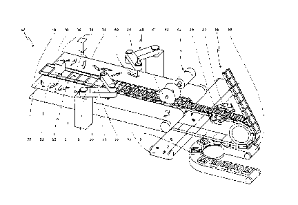
Fig. 4 shows a close-up perspective view of a third and presently most
preferred embodiment of a processing plant for sardines 32'. A sardine 22' may
enter the processing plant 32' placed on a transport band 34'. The sardine 22'
may be placed on the transport band 34' in any permitted orientation where all
parts of the sardine 22' is located within the limits of the transport band
34', the
sardine is not overlapping or being overlapped by another object and at least
some amount of space is available between the sardine 22' and any other
object or sardine. The permitted position should be understood to mean any
position where one gill cover is facing the transport band 34' and the other
gill
cover is facing the opposite (upwards) direction.
The transport band travels in the direction of the arrow. At the beginning the
transport band 34 passes a camera detection unit 36' comprising a CCD
camera. The camera detection unit 36' creates a digital representation of the
sardine 34' and communicates the digital representation to a computer (not
shown). The computer (not shown) calculates data such as size, position,
orientation and location of the transition between the body part and the end
waste part of the sardine 22' passing on the transport band 34'. A robot 38'
is
placed and has its working envelope downstream in relation to the camera
detection unit 36'. The robot 38' may e.g. be of the type FlexpickerTM. The
computer (not shown) controls the robot 38'. The computer (not shown)
additionally has information about the velocity of the transport band 34' and
determines when the sardine 22' is within reach of the robot 38'. The robot
38'
comprises a robot arm 39' and an end effector 40' at the end of the robot arm
39'. The robot 38' collects the sardine 22' by either fastening the sardine
22'
mechanically between two end effectors 40' or alternatively by fastening the
sardine 22' onto one end effector 40' by suction principle. The end effector
40'
should be applied near the presumed centre of gravity of the sardine 22' for
optimal stability. The end effector may lift the sardine 22' a small distance
CA 02739996 2011-04-08
WO 2010/040802 PCT/EP2009/063094
19
above the transport band 34' and reorient the sardine 22' such that it is
located
directly under a separation arrangement 42'.
The separation arrangement 42' is fixated to the robot arm 39' near the end
effector 40', and comprises two rotating circular knives where the first knife
41'
is used for separating the head part of the sardine 22' from the body part of
the
sardine 22' and the second knife 43' is used for separating the tail part of
the
sardine 22' from the body part of the sardine 22'. The first knife 41' and the
second knife 43' are adjustable with respect to the distance from the end
effector 40'. The first knife 41' may move to a position just above the
transition
between the body part of the sardine 22' and the head part 23 of the sardine
22' and the second knife 43' may move to a position just above the transition
between the body part of the sardine 22' and the tail part of the sardine 22'.
The
sardine 22' is severed either by using the end effector 39' to lift the
sardine 22'
into contact with the cutting arrangement 42' or alternatively by lowering the
cutting arrangement 42' into contact with the sardine 22'. The above
configuration is used for minimizing waste. The second knife 41' is
alternatively
used to separate the tail part and the body part of the sardine 22' at a fixed
position in relation to the first knife 43' when there is a need for a
standardized
size of the sardine 22'. If the tail part of the sardine 22' is desirable the
second
knife 41' may be omitted.
An evisceration arrangement 56 may be provided fixated to the robot 38' above
the separation arrangement 42'. The evisceration arrangement comprises a
vacuum suction device for removing the guts of the sardine 22'. By lifting the
sardine a small distance the severed end of the body of the sardine 22' where
the head of the sardine 22' was attached to the body of the sardine 22' prior
to
separation may be put in contact with the suction device and the guts of the
sardine 22' may be removed by applying suction.
A waste receptacle 46' is located parallel with respect to the transport band
34'
for collecting the severed end waste parts of the sardine 22', which will fall
off
during separation. The transport band 34' has a second end after passing the
CA 02739996 2011-04-08
WO 2010/040802 PCT/EP2009/063094
robot 38'. At the second end an end waste receptacle 44' is provided for
receiving waste objects 48' not picked up by the robot 38'. Such waste object
48' may be fish belonging to an undesired species or sardines 22' having an
unsuitable size, e.g. being too small or too large or not fitting into any
5 predefined size group. Waste objects 48' are detected by the optical
measurement unit 36' as such and are allowed to pass the robot 38' without
being collected.
The transport bands 34' may preferably have a variable velocity controlled by
10 the computer to allow for an efficient utilization of the robot 38'.
After separation the sardine 22' is placed in a can 50' located on a packing
conveyer 52'. Typically, each can 50' is filled with 5-10 sardines 22'. The
cans
50' preferably are filled such that the weight of each can is standardized.
This
15 may be reached by either weighting each fish by including a weight sensor
in
the end effector 40' of the robot 38' or by measuring the weight of the can
50'
when filled at the packing conveyor 52'. Alternatively, the cans 50' may be
filled
with a constant number of sardines 22', such as 7, and afterwards weighed.
Cans 50' falling within a specified weight range may proceed to shipping,
20 whereas overweighed or underweighted cans 50' falling outside the size
range
proceed to a manual equalisation station (not shown) where one or more
sardines 22' are removed from the overweighed cans 50' and added to the
underweighted cans 50'.
Fig. 5a-d shows a series describing the severing of the head part 23 and the
body part 26 of a sardine 22. It should be noted that the separation of the
head
part 23 is shown here, however, the tail part 27 may be separated in a similar
way which will be evident to a skilled person in the art.
Fig. 5a shows an end effector 40" according to the present invention and
constituting a processing station comprising a severing arm 60, a gripping
unit
61 and an evisceration station 56". The gripping unit 61 comprises an inner
plate 62 and an outer plate 63. The inner and outer plates 62, 63 are parallel
CA 02739996 2011-04-08
WO 2010/040802 PCT/EP2009/063094
21
and are having an in-between distance for accommodating the body part 26.
The outer plate 63 is movable in direction towards the inner plate 62 for
gripping and releasing the body part 26. The outer plate 63 is attached to the
inner plate 62 and the rest of the gripping unit 61 by two actuator rods 64
located near the upper end of the plates 62, 63. The actuator rods 64 comprise
electromechanical actuators for moving the outer plate 63. The inner plate 62
has a fixed knife 43" attached. The fixed knife 43" is oriented towards the
outer
plate 63, i.e. perpendicular in relation to the inner and outer plates 62, 63.
The
severing arm 60 is mounted above and outside the inner and outer plate and is
pivotable in direction towards the fixed knife 43". The severing arm 60 is
connected to an electric motor 66.
The severing arm 60 constitutes a combined mobile knife 41" and an
evisceration station 56". The evisceration station 56" comprises a suction
member 67 fixed in a juxtaposed position on the side of the mobile knife 41".
The mobile knife 41" defines a hole through which the suction member 67 of
the evisceration station 56" may communicate. The evisceration station 56" is
further connected to a hose 65 for providing a low pressure and for
transporting
the guts of the sardine to a waste receptacle (not shown).
Fig. 5b shows the end effector 40' after gripping the sardine 22 between the
inner and outer plate 62, 63. The end effector 40' is attached to an
industrial
robot or the like not shown but described above in connection with Figs 2-4
and
the end effector 40' is thus movable in three dimensions within its working
envelop. The sardine 22 is gripped between the inner and outer plates 62, 63
by lowering the end effector 40' onto the sardine in a specific position
determined by the processing unit and optical measurement unit (both not
shown here) and subsequently moving the outer plate 63 towards the inner
plate 62 for fixating the body part 26. The specific position is contemplated
to
be the position where the transition 30 between the head part 23 and the body
part 26 is located between the fixed knife and the mobile knife. The specific
position is also contemplated to be a position where the fish body is fixated
between the inner and outer plates 62 63. The sardine 40' is provided on a
CA 02739996 2011-04-08
WO 2010/040802 PCT/EP2009/063094
22
transport band (not shown) as described in connection with Figs 2-4. The
fixation force between the inner and outer plates 62, 63 also allow lifting of
the
sardine 22.
Fig. 5c shows the severing arm 60 pivoting towards the fixed knife 43" and the
sardine 22. The severing arm 60 is propelled by the electric motor 66. When
the mobile knife 41" reaches the transition 30 between the head part 23 and
the body part 26 of the sardine 22 the sardine 22 will be squeezed and severed
from two opposite direction by the mobile knife 41" and the fixed knife 43".
Fig. 5d shows the severing arm 60 in its end position when the mobile knife 41
has reached and contacted the fixed knife 43". The knives 41", 43" are
preferably slightly offset in order to operate in the same principle as a pair
of
scissors, which will assure a reliable severing.
The severing is preferably made above a receptacle for collecting the end
waste parts of the sardine 22. The sardine may thus be lifted and move to such
position before the severing takes place.
When the severing arm 60 has reached its end position the suction member 67
will be positioned juxtaposed the body part 26 of the sardine 22, i.e.
juxtaposed
the transition between the head part 23 and the body part 26 of the sardine
22.
In the present position the suction member 67 may begin removing the guts of
the sardine 22 by suction. When the guts of the sardine 22 has been removed,
the severing arm 60 may pivot back to its starting position and the end
effector
40' may be lifted and moved to the next sardine.
Fig. 6 shows an alternative embodiment of an end effector 40"'. The end
effector 40"' comprises a suction element 45 for attaching to the sardine 22.
The suction element 45 is attached to a lifting rod 68, which may be elevated
by a lifting actuator 69. The suction member 45, and thereby the sardine 22
may be collected while the lifting rod is in a low position. The end effector
40"'
further comprises a separation arrangement 42"' having first rotating knife 41
".
CA 02739996 2011-04-08
WO 2010/040802 PCT/EP2009/063094
23
and a second rotating knife 43"'. The rotating knives 41"', 43"' may be
shifted
in the longitudinal direction as shown by the arrows by the use of a spindle
70.
This allows the knives 41"', 43"' to be positioned at the transition between
the
head part of the sardine 22 and the end waste part of the sardine 22. The
suction element 45 may be lifted according to the arrow to a high position so
that the sardine 22 comes into contact with the rotating knives 41 "', 43"'
for
severing the head part of the sardine 22 and the tail part of the sardine 22
from
the body part of the sardine 22.The rotating knives 41 "', 43"' are powered by
a
motor 71.
The embodiments in Figs 3 and 4 are shown with two parallel transport bands
34' and two robots 38' situated around a single centrally located packing
conveyer 52'. It has been shown that this configuration makes more efficient
usage of the transport conveyer 52'.
The decapitated and eviscerated sardine may subsequently be further
processed according to the wish of the customer. Such further processing may
involve packing in containers, cooking, freezing etc.
A variety of motors or motion generating devices such as e.g. pneumatic,
electric or hydraulic devices may drive the transport bands, bulk elevators
and
conveyers. A gear, transmission or the like may or may not be used for
increased efficiency or controllability.
The camera may be replaced with any device capable of making a digital
representation of an object placed on the conveying surface. Such device may
e.g. be a device detecting and possibly transmitting electromagnetic waves
such as e.g. visual light, ultraviolet light, infrared light, radar waves or
microwaves. Other alternative devices may use ultrasound or the like for
making the digital representation.
The knife arrangements may be replaced with any similar separation device
such as a saw, a pair of scissors or a water jet.
CA 02739996 2011-04-08
WO 2010/040802 PCT/EP2009/063094
24
The systems and methods described above is preferably used together with
fish belonging to the sardine group, such as herring, mackerel or anchovies.
However, it is contemplated that the technologies described above may as well
be applicable to the processing of any kind of fish or similar foodstuff.
The usage of the term downstream should be understood in relation to the
conveying or transport direction of the fish.
if using a plurality of robots, the computer (not shown) also determines which
specific robot will pick up a specific sardine, whereby each robot may be
designated to pick up all sardines within a specific size range, or
alternatively
any robot may be used to pick up any sardine.
CA 02739996 2011-04-08
WO 2010/040802 PCT/EP2009/063094
List of parts
10. Processing plant according to a first embodiment
12. Bulk container
14. Bulk receptacle
5 16. Bulk elevator
18. Loading area
20. Underwater conveyor
22. Sardine (fish)
23. Head part (end waste part)
10 24. Gill cover
25. Pectoral fin
26. Body part
27. Tail part (end waste part)
30. Transition between head part and body part
15 31. Transition between tail part and body part
32. Processing plant according to a further embodiment
34. Transport band
36. Camera detection unit
38. Robot (industrial)
20 39. Robot arm
40. End effector
41. First knife
42. Separation arrangement
43. Second knife
25 44. End waste receptacle
45. Suction element
46. Waste receptacle
48. Waste object
49. Waste conveyer
50. Can
51. Slits
52. Packing conveyer
53. Compartment wall
CA 02739996 2011-04-08
WO 2010/040802 PCT/EP2009/063094
26
54. Body compartment
55. End compartment
56. Evisceration station
58. Packing station
59. Container conveyer
60. Severing arm
61. Gripping unit
62. Inner plate
63. Outer plate
64. Actuator rod
65. Hose
66. Electric motor
67. Suction member
68. Lifting rod
69. Lifting actuator
70. Spindle
71. Motor
CA 02739996 2011-04-08
WO 2010/040802 PCT/EP2009/063094
27
The present invention is characterized by the following points:
1. A system for processing fish of a single species and of different anatomic
constitution having at least an end waste part, a body part and a transition
between the end waste part and the body part, the system comprising:
a frame, defining a first end and a second end opposite the first
end and including a fish loading area for receiving the fish at the first end
and a
fish unloading area at the second end,
an optical measurement unit located at the first end monitoring at
least part of the fish loading area for producing a digital representation of
the
fish,
a grabbing unit mounted on the frame downstream in relation to
the optical measurement unit between the first end and the second end for
collecting the fish from the fish loading area and placing the fish on the
fish
unloading area,
a processing unit for receiving the digital representation of the
fish, determining the transition between the end waste part and the body part
of
the fish and controlling the grabbing unit, and
a separation arrangement located at or alternatively downstream in
relation to the grabbing unit for separating the end waste part from the body
part at the transition.
2. The system according to point 1, wherein the fish loading area and/or the
fish unloading area comprises a conveyer assembly, such as e.g. a conveyer
belt.
3. The system according to points 2, wherein the conveyer assembly has a
variable conveying velocity.
4. The system according to any of the points 2-3, wherein the conveyer
assembly comprises a first and a second conveyer wherein the first conveyer
and the second conveyer extending parallel for at least a part of the distance
between the first end and the second end.
CA 02739996 2011-04-08
WO 2010/040802 PCT/EP2009/063094
28
5. The system according to point 4, wherein the first conveyer and the second
conveyer have an opposite conveying direction for at least a part of the
distance between the first end and the second end.
6. The system according to any of the previous points, wherein the body part
having a body length longer than a specific maximum length and the separation
arrangement separates the body part into a first body part having a length
equal to the maximum length and a second body part having a length equal to
the body length of the body minus the maximum length.
7. The system according to any of the previous points, wherein the separation
arrangement is fixed onto the grabbing unit.
8. The system according to any of the previous points, wherein the optical
measurement unit comprises a CCD camera or alternatively a laser tracking
system.
9. The system according to any of the previous points, wherein the grabbing
unit comprises one or more industrial robots.
10. The system according to any of the previous points, wherein the grabbing
unit comprises an electromechanical or pneumatic gripping member or
alternatively a suction member for moving the fish.
11. The system according to any of the previous points, wherein the separation
arrangement comprises a rotating blade or alternatively a reciprocating blade.
12. The system according to any of the previous points, further providing one
or
more additional processing stations such as an evisceration station or a
packing station.
CA 02739996 2011-04-08
WO 2010/040802 PCT/EP2009/063094
29
13. The system according to any of the previous points, further providing one
or
more additional unloading areas such as a reject station or a waste station
for
disposing the end waste part.
14. The system according to any of the previous points, wherein the processing
unit includes means for determining the transition between the end waste part
and the body part by measuring an overall length of the fish and calculating a
fraction of the overall length corresponding to the length of the end waste
part.
15. The system according to any of the previous points, wherein the processing
unit is supplied with a list of size groups constituting size ranges, the fish
is
designated into one specific size group determined by measuring an overall
length of the fish and the transition between the end waste part and the body
part is determined by the size group.
16. The system according to any of the previous claims, further including a
packing station, the packing station providing a multitude of containers for
receiving the fish, the multitude of containers are designated different size
ranges, the fish is packed in the corresponding container according to the
size
of the fish, which is derived from the digital representation.
17. The system according to any of the previous points, wherein the end waste
part comprises a head part, i.e. the head and the gills of the fish.
18. The system according to any of the previous points, wherein the processing
unit includes means for determining the transition between the head part and
the body part by the position of the gill cover or alternatively the position
of the
pectoral fin or alternatively by the surface area of the fish or alternatively
by the
circumference of the fish or alternatively by the colour of the fish or
alternatively
by the length of the fish or alternatively by the contour/outer periphery of
the
fish.
CA 02739996 2011-04-08
WO 2010/040802 PCT/EP2009/063094
19. The system according to any previous points, wherein the end waste part
comprising the tail part of the fish.
20. The system according to any of the previous points, wherein the processing
5 unit includes means for determining the transition between the tail part and
the
body part by the position of the thinnest part of the fish.
21. A processing station for processing fish of a single species and of
different
anatomic constitution having at least an end waste part, a body part and a
10 transition between the end waste part and the body part, the processing
station
constituting a combined grabbing unit, separation unit and evisceration unit
where:
the grabbing unit comprising a first surface and an opposite located
second surface, the first and second surfaces being movable relative to one
15 another, the first and second surfaces defining a enclosure for
accommodating
the fish body, the enclosure having an open end for exposing the transition
between the end waste part and the body part,
the separation unit being located at the open end of the enclosure
and comprising a set of separating elements, the set of separating elements
20 defining an open position defining a distance between the set of separating
elements for accommodating the transition, and a closed position where the set
of separating elements is severing the transition, and
the evisceration unit comprising a suction unit for subjecting the
transition to a low pressure, the evisceration unit having an active position
25 where the suction unit is positioned juxtaposed the open end, and a passive
position where the suction unit is positioned remote from the open end.
22. The processing station according to point 21, wherein the suction unit is
mounted on the set of separating elements and where the open position
30 corresponds to the passive position and the closed position corresponds to
the
active position.
CA 02739996 2011-04-08
WO 2010/040802 PCT/EP2009/063094
31
23. The processing station according to any of the points 21-22, wherein the
first and second surfaces are undulated.
24. A method for processing fish of a single species and of different anatomic
constitution having at least an end waste part, a body part and a transition
between the end waste part and the body part, the method comprising:
providing a frame, defining a first end and a second end opposite
the first end and including a fish loading area at the first end and a fish
unloading area at the second end,
providing an optical measurement unit located at the first end
monitoring at least part of the fish loading area for producing a digital
representation of the fish,
providing a grabbing unit mounted on the frame downstream in
relation to the optical measurement unit between the first end and the second
end for collecting the fish from the fish loading area and placing the fish on
the
fish unloading area,
providing a processing unit for receiving the digital representation
of the fish and controlling the grabbing unit, and
providing a separation arrangement located at or downstream in
relation to the grabbing unit for separating the end waste part from the body
part at the transition,
processing the fish by performing the following steps:
placing the fish on the fish loading area,
determining the transition between the end waste part and the
body part of the fish by using the processing unit,
collecting the fish by using the grabbing unit controlled by the
processing unit, and
separating the end waste part from the body part at the transition.
25. The method according to point 24, further comprising any of the features
of
points 1-20.
CA 02739996 2011-04-08
WO 2010/040802 PCT/EP2009/063094
32
26. A processing method for processing fish of a single species and of
different
anatomic constitution having at least an end waste part, a body part and a
transition between the end waste part and the body part, the processing
method comprise providing a processing station constituting a combined
grabbing unit, separation unit and evisceration unit where:
the grabbing unit comprising a first surface and an opposite located
second surface, the first and second surfaces being movable relative to one
another, the first and second surfaces defining an enclosure and the enclosure
having an open end,
the separation unit being located at the open end of the enclosure
and comprising a set of separating elements, the set of separating elements
defining an open position defining a distance between the set of separating
elements for accommodating the transition, and a closed position where the set
of separating elements are severing the transition, and
the evisceration unit comprising a suction unit and having an active
position where the suction unit is positioned juxtaposed the open end, and a
passive position where the suction unit is positioned remote from the open
end,
the processing method further comprise the steps of:
accommodating the fish body in the enclosure defined between the
first and second surfaces and exposing the transition between the end waste
part and the body part at the open end of the enclosure while having the
separation unit in the open position and the evisceration unit in the passive
position, and
Severing and eviscerating the fish by moving the mobile knife to
the closed position and subsequently, or alternatively simultaneously, moving
the evisceration unit to the active position and subjecting the transition to
a low
pressure.
27. The method according to point 26, further comprising any of the features
of
points 22-23.