Language selection

Search

Patent 2740049 Summary

Third-party information liability

Some of the information on this Web page has been provided by external sources. The Government of Canada is not responsible for the accuracy, reliability or currency of the information supplied by external sources. Users wishing to rely upon this information should consult directly with the source of the information. Content provided by external sources is not subject to official languages, privacy and accessibility requirements.

Claims and Abstract availability

Any discrepancies in the text and image of the Claims and Abstract are due to differing posting times. Text of the Claims and Abstract are posted:

  • At the time the application is open to public inspection;
  • At the time of issue of the patent (grant).
(12) Patent Application: (11) CA 2740049
(54) English Title: UNIVERSAL SPINAL BOARD
(54) French Title: PLANCHE DORSALE UNIVERSELLE
Status: Deemed Abandoned and Beyond the Period of Reinstatement - Pending Response to Notice of Disregarded Communication
Bibliographic Data
(51) International Patent Classification (IPC):
  • A61G 1/00 (2006.01)
  • A61F 5/05 (2006.01)
  • A61G 1/04 (2006.01)
(72) Inventors :
  • DONALDSON, CHARLOTTE A. (Canada)
  • SMITH, MEGAN M. (Canada)
(73) Owners :
  • CHARLOTTE A. DONALDSON
  • MEGAN M. SMITH
(71) Applicants :
  • CHARLOTTE A. DONALDSON (Canada)
  • MEGAN M. SMITH (Canada)
(74) Agent:
(74) Associate agent:
(45) Issued:
(22) Filed Date: 2011-05-16
(41) Open to Public Inspection: 2012-11-16
Availability of licence: N/A
Dedicated to the Public: N/A
(25) Language of filing: English

Patent Cooperation Treaty (PCT): No

(30) Application Priority Data: None

Abstracts

English Abstract


The Universal Spinal Board is a back board designed to completely immobilize a
full
spectrum of victim ages, heights and weights. This invention significantly
reduces
movement of victims who may have suffered spinal cord injury, reducing the
risk of
further injury to the spine during the rescue procedure. Ridges along the
lateral sides of
the spinal board combined with runners along the underside of the board allow
for a
wide variance in free moving strap placement. This accommodates any body size.
A
textured foam rubber surface extends slightly beyond the rigid portion of the
spinal
board, assisting in holding straps securely. This textured foam rubber surface
also
moulds to and holds the victim in place on the board. Rubber spacers
surrounding hand
holes serve to reduce potential injury to lifesavers. The Universal Spinal
Board secures
small and large victims and aids in the comfort and safety of all users.


Claims

Note: Claims are shown in the official language in which they were submitted.

1
Claims
The embodiments of the invention in which an exclusive property or privilege
is
claimed are as follows.
1. A spinal board wherein the lateral sides of the board are constructed in a
ridge and valley design for the purpose of varying the placement of straps
for securing a victim on the board.
2. A spinal board wherein the upper surface of the board is covered with a
textured foam rubber matting to facilitate securing the victim.
3. A spinal board wherein the upper surface of the board is covered with a
textured foam rubber matting to provide increased victim comfort.
4. A spinal board wherein the upper surface of the board is covered with a
textured foam rubber matting to provide insulation for the victim.
5. A spinal board wherein the textured foam rubber matting in claim 2 is
extended beyond the edge of the surface of the board to facilitate
increased strap grip on the board.
6. A spinal board wherein the width of the board is maintained for its entire
length to increase structural strength of the board.
7. A spinal board wherein the width of the board is maintained for its entire
length to increase leveraging opportunities to assist with moving the board
while transporting the board, either while empty or with a victim secured to
it.
8. A spinal board wherein runners are placed on the bottom side of the
board, parallel to the sides of the board and extending the length of the
board to facilitate securing straps to the board.
9. A spinal board wherein runners are placed on the bottom side of the
board, parallel to the lateral sides of the board and extending the length of
the board to facilitate providing greater options for strap placement.
10. A spinal board wherein runners are placed on the bottom side of the
board, parallel to the lateral sides of the board and extending the length of
the board to provide a means to assist with moving or sliding the board
while either loaded or empty.

2
11. A spinal board wherein rubber spacers are placed on the bottom side of
the board to reduce finger or hand pinch during lifting or placing the board
down.
12. A spinal board wherein rubber spacers are placed on the bottom side of
the board to act as shock absorbers to reduce impact to the victim when
the loaded board is set down.
13. A spinal board wherein rubber spacers are placed on the bottom side of
the board to ease access to lifting slots or handles.
14. A spinal board wherein handling slots are placed wide enough apart to
assist the rescuer with lift efficiency.
15. A spinal board wherein the straps are different colours to prevent
confusion and expedite securing the victim.
16. A spinal board wherein the colour of the buckles matches the strap colour
to prevent confusion and expedite securing the victim.
17. A spinal board wherein if a single colour strap is used, each matching set
of buckles are a different colour to prevent confusion and expedite
securing the victim.

Description

Note: Descriptions are shown in the official language in which they were submitted.


CA 02740049 2011-05-16
1
Description
This invention is a spinal board that immobilizes spinal cord injury victims
of all sizes.
A standard spinal board is designed primarily for use on adult victims.
Special boards are
available to accommodate children and youths; however, neither board can
properly
secure a wide range of victim shapes and sizes. Unfortunately an accident
victim's size
cannot be predetermined and carrying multiple size spinal boards to an
accident scene is
impractical. As a result, many accident victims with spinal damage are placed
at risk of
incremental trauma to the spinal cord due to inadequate immobilization during
rescue and
transportation to medical facilities.
Standard spinal boards typically incorporate slots along the sides of the
board to facilitate
strap placement. While this can accommodate most adults, these slots can
restrict the
optimal strap placement on children and youths. This less than ideal strap
placement on
many victims can allow body movement, which can have catastrophic results for
those with
spinal injuries. Aquatic rescues are further complicated by the "slip and
slide" factor created
by wet surfaces on a conventional spinal board.
This spinal board incorporates several features which improve the performance
of
conventional spinal boards in terms of immobilization of the victim. They are
all designed to
reduce victim movement. This board also improves the comfort level of victims
during
prolonged periods spent on the spinal board.
Drawings included in the Application:
Figure 1. is a top view of the spinal board.
Figure 2. is a bottom view of the spinal board.
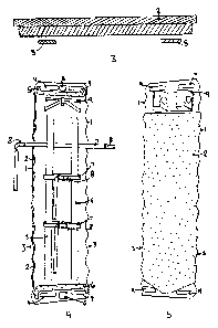
Figure 3. is a cross sectional view of the spinal board at the mid-point of
its length.
Figure 4. is a bottom view of the spinal board with all straps attached.
Figure 5. is a. top view of the spinal board with the head pack attached.
Modifications have been made to the means in which the straps are positioned
and
secured on the board and victim, thus significantly reducing body and spinal
movement.
Figures 1., 2., 4. and 5. show a top and bottom view of the board, outlining
the ridges (1)
along the full length of both sides of the Universal Spinal Board. This ridge
and valley
design offers a practical means of providing limitless strap placement to
accommodate all
body sizes.

CA 02740049 2011-05-16
2
To enhance the ability to secure a wide range of victim sizes to the board, a
means was
required to allow straps to freely slide the entire length of the board
without becoming
separated from the board and potentially lost. To facilitate these
requirements, figure 2.
and 4. shows runners (5) attached to the bottom of the board and running the
length of the
torso portion. Figure 3 shows a cross section of the board at the mid-point
and
demonstrates the positioning of these same runners (5) in relation to the
bottom of the
board. These runners can also serve as slides for the board during rescue.
This reduces
strain on the rescuer and also reduces the chance of additional victim
movement in
removal from the accident scene.
Figures 1., 2., 3., 4. and 5. all show the placement of textured foam rubber
matting (2) on
the upper surface of the spinal board. This rubber (2) serves several
purposes. The rubber
surface over the entire victim contact surface allows the victim's body to
somewhat mould
into the rubber, ensuring it is better held in place. This further prevents
movement,
especially during an aquatic rescue. Figure 2., 3. and 4. show this textured
foam rubber
matting (2) extending beyond the edge of the rigid, weight bearing portion of
the board.
This overlap allows the straps to better grip the board, thus further reducing
strap and
subsequent victim movement. This foam rubber surface also significantly
increases the
victims comfort during an extended period on the board. This increased comfort
reduces
stress levels in the victim and provides for a greater chance to keep the
victim calm during
and after the rescue. Finally, the foam surface provides insulation and warmth
for the
victim.
Figures 1., 2., 4. and 5. show the board maintains its full width (3) for its
entire length when
compared to a standard board's tapered shape. This makes the board easier for
rescuers
to manoeuvre due to increased leverage.
Figures 2. and 4. shows various rubber spacers (6) around the hand holes (4)
which
facilitate rescuers gripping the board without finger pinch during lifting the
board or setting it
down. These also act as shock absorbers when placing the board and secured
victim on a
hard surface.
During rescue procedures, high stress levels and chaotic work settings can
create potential
delays or issues resulting from confusion in strap selection, coupling or
securing. Figure 4.
shows strap (7) placement on the board. On the Universal Spinal Board, each of
these
straps (7) is a different colour, or if one colour straps are used, each strap
has a different

CA 02740049 2011-05-16
3
colour buckle (8) to minimize confusion or delays while securing the victim.
Figure 5 shows
the placement of the head pack (9) on the board.

Representative Drawing
A single figure which represents the drawing illustrating the invention.
Administrative Status

2024-08-01:As part of the Next Generation Patents (NGP) transition, the Canadian Patents Database (CPD) now contains a more detailed Event History, which replicates the Event Log of our new back-office solution.

Please note that "Inactive:" events refers to events no longer in use in our new back-office solution.

For a clearer understanding of the status of the application/patent presented on this page, the site Disclaimer , as well as the definitions for Patent , Event History , Maintenance Fee  and Payment History  should be consulted.

Event History

Description Date
Application Not Reinstated by Deadline 2014-05-16
Time Limit for Reversal Expired 2014-05-16
Inactive: Adhoc Request Documented 2014-02-20
Deemed Abandoned - Failure to Respond to Maintenance Fee Notice 2013-05-16
Inactive: Cover page published 2012-11-26
Application Published (Open to Public Inspection) 2012-11-16
Inactive: Office letter 2011-06-06
Inactive: First IPC assigned 2011-06-03
Inactive: IPC assigned 2011-06-03
Filing Requirements Determined Compliant 2011-05-30
Inactive: Filing certificate - No RFE (English) 2011-05-30
Application Received - Regular National 2011-05-30
Small Entity Declaration Determined Compliant 2011-05-16

Abandonment History

Abandonment Date Reason Reinstatement Date
2013-05-16

Fee History

Fee Type Anniversary Year Due Date Paid Date
Application fee - small 2011-05-16
Owners on Record

Note: Records showing the ownership history in alphabetical order.

Current Owners on Record
CHARLOTTE A. DONALDSON
MEGAN M. SMITH
Past Owners on Record
None
Past Owners that do not appear in the "Owners on Record" listing will appear in other documentation within the application.
Documents

To view selected files, please enter reCAPTCHA code :


To view images, click a link in the Document Description column. To download the documents, select one or more checkboxes in the first column and then click the "Download Selected in PDF format (Zip Archive)" or the "Download Selected as Single PDF" button.

List of published and non-published patent-specific documents on the CPD .

If you have any difficulty accessing content, you can call the Client Service Centre at 1-866-997-1936 or send them an e-mail at CIPO Client Service Centre.


Document
Description 
Date
(yyyy-mm-dd) 
Number of pages   Size of Image (KB) 
Description 2011-05-16 3 120
Abstract 2011-05-16 1 24
Claims 2011-05-16 2 70
Drawings 2011-05-16 4 57
Representative drawing 2012-01-11 1 12
Cover Page 2012-11-26 1 43
Filing Certificate (English) 2011-05-30 1 156
Notice: Maintenance Fee Reminder 2013-02-19 1 120
Courtesy - Abandonment Letter (Maintenance Fee) 2013-07-11 1 171
Second Notice: Maintenance Fee Reminder 2013-11-19 1 118
Notice: Maintenance Fee Reminder 2014-02-18 1 121
Correspondence 2011-05-30 1 17
Correspondence 2011-05-30 1 40