Note: Descriptions are shown in the official language in which they were submitted.
CA 02740444 2011-05-13
1
METHOD FOR CONTROLLING THE FUNCTIONING OF A TWIN INTERNAL
COMBUSTION ENGINE IN A VEHICLE, ESPECIALLY A FIRE-FIGHTING
VEHICLE
Application field of the invention
The present invention refers to a method for controlling the
functioning of a twin internal combustion engine in a
vehicle, especially a fire-fighting vehicle.
Description of the prior art
Vehicles, especially fire-fighting vehicles, comprising a
pair of internal combustion engines connected in parallel are
known. They are vehicle having big dimensions, whose gross
weight may be about 50 tons or more, that are used in special
fields or situations, such as for example in airports, where
a fast intervention is necessary, carrying people and a high
quantity of fire extinguishing material.
One single engine would not be enough to obtain the necessary
pickup torque, above all because at present single engines
having enough power for these needs are not available, also
because they have to comply with the current emission
standards (Euro 4/5).
Therefore both engines contribute to the vehicle's traction
in order to be faster in reaching the intervention place,
after that one of the two engines is used as a pump to
sprinkle the fire extinguishing liquid on the intervention
CA 02740444 2011-05-13
2
place itself.
The methods known for controlling the functioning of the two
engines still have margins of improvement, regarding the
optimization of the ratio between engine performance and
intervention time, as a function also of the weight and of
the dimensions of the vehicle. The desired improvements also
relate to the management/control of the two engines
functioning as a traction engine or as a pumping engine.
Summary of the invention
Therefore the aim of the present invention is to provide
a method for controlling the functioning of a twin internal
combustion engine in a vehicle, especially a fire-fighting
vehicle, suitable for minimizing the intervention time of the
vehicle itself.
The object of the present invention is a method for
controlling the functioning of a twin internal combustion
engine in a vehicle, especially a fire-fighting vehicle, each
engine being equipped with automatic transmission, suitable
to transfer the torque generated at a torque distributor,
comprising: a first clutch suitable to connect a first
engine unit of said twin internal combustion engine to a
delivery pump of the liquid; a second clutch suitable to
connect said first engine unit to the traction system of the
vehicle; a third clutch suitable to connect a second engine
CA 02740444 2011-05-13
3
unit of said twin internal combustion engine to the traction
system of the vehicle, characterized in that said control has
an activation step and a deactivation step of said delivery
pump of the liquid, by means of the opening or of the closing
of said first clutch with a vehicle speed lower than a
threshold higher than zero, and in a condition of
decelerating vehicle, with the simultaneous opening or
closing of said second clutch, if said conditions occur
within a certain interval of time from an activation or a
deactivation request.
A particular object of the present invention is a method
for controlling the functioning of a twin internal combustion
engine in a vehicle, especially a fire-fighting vehicle, as
described more fully in the claims, which are an integral
part of this description.
Brief description of the Figures
Further purposes and advantages of the present invention
will become clear from the following detailed description of
a preferred embodiment (and its alternative embodiments) and
the drawings that are attached hereto, which are merely
illustrative and non-limitative, in which:
figures 1.1 and 1.2 show respectively a top and a lateral
view of a vehicle frame equipped with a double engine;
figures 2.1 and 2.2 show examples of two alternative
CA 02740444 2011-05-13
4
structure schemes of the torque distributor block which
distributes the torque generated by the two engines;
figures from 3 to 6 show flowcharts illustrating the
control method according to the present invention.
In the drawings the same reference numbers and letters
identify the same elements or components.
Detailed description of preferred embodiments of the
invention
Figures 1.1 and 1.2 show a vehicle suitable to realize
the method according to the present invention comprising two
adjacent engine units A, B respectively comprising engines 1
and 2, each one of them being provided with its own
transmission units 3, 4, comprising an automatic
transmission, preferably equipped with torque converter,
which transfers the generated torque to a block 5,
substantially of a type known in the art, which functions as
a torque distributor (torque summation box).
The latter, according to the control signals received
from an electronic control unit not shown in the figures, can
work according to one of two operating modes:
- in a first operating mode the torque distributor 5 sums up
the torque contributions deriving from the two engines and
transfers the resulting torque to the propeller shaft 6 which
in turn transfers it to the driving axles of the vehicle: in
CA 02740444 2011-05-13
the example shown, the vehicle is equipped with four driving
axles, but obviously other configurations are also possible;
- in a second operating mode the torque distributor 5
disconnects the traction of one of the two engines, for
5 example the engine unit A in the figures, and connects the
engine to a pump not shown in the figures, so that the engine
functions as a pumping engine for delivering a liquid, for
example a fire-fighting liquid; while the other engine unit B
is used for the usual traction of the vehicle.
The circuit block diagram of the torque distributor is
shown in two possible alternative embodiments in figures 2.1
and 2.2.
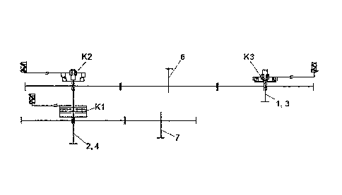
In a first alternative embodiment (fig. 2.1) the torque
distributor essentially comprises a first clutch Kl suitable
to connect the propeller shaft of the first engine unit A (2,
4) to the shaft 7 of the delivery pump of the liquid, and a
second clutch K2 suitable to connect the propeller shaft of
the first engine unit A (2, 4) to the propeller shaft 6
transmitting the traction torque of the vehicle. In addition
a third clutch K3 is present suitable to connect the
propeller shaft of the second engine unit B (1, 3) to the
propeller shaft 6 transmitting the traction torque of the
vehicle. In this first alternative embodiment only one of the
two engines (the engine unit A) may function as a pumping
CA 02740444 2011-05-13
6
engine.
In a second alternative embodiment (fig. 2.2) also the
engine unit B may function as a pumping engine. Then the
torque distributor comprises, in addition to the elements of
the first alternative embodiment, a fourth clutch K4 suitable
to connect the propeller shaft of the second engine unit B
(1, 3) to the shaft 7 of the delivery pump of the liquid. In
this second alternative embodiment both engines may function
as pumping engines, guaranteeing a higher security
functioning: if a failure occurs to one engine unit, the
other engine unit may replace it. In general the two engine
units may alternatively control the pump.
The method for controlling the functioning of the twin
internal combustion engine according to the invention is
actuated by controlling the functioning of the torque
distributor, which determines the passage between said first
and said second operating mode.
A relevant aspect of the method according to the
invention is the fact that it controls the activation and
also the deactivation of the pump of the fire-fighting liquid
also when the vehicle is still moving, so that the operations
are sped up. The vehicle speed, however, should be lower than
a safety threshold, and the vehicle has to be decelerating.
With reference to the flowcharts of the figures 3 and 4,
CA 02740444 2011-05-13
7
in the starting condition (START1) the vehicle is moved by
both engines, then there is the condition in which both
clutches K2 and K3 are closed, while the clutch K1 is open,
in the torque distributor.
The activation or the deactivation of the pump of the
fire-fighting liquid is controlled by the operator, for
example by pressing a button on the dashboard.
Some preliminary controls are actuated, suitable to
verify the correctness of the procedure.
If the button is held pressed for longer than a threshold
(e.g. 0.5 s) (block 30), the procedure is activated verifying
if the accelerator pedal is released (decelerating vehicle)
and if the speed V of the vehicle is lower than a threshold,
e.g. V < 60km/h (block 31). It is not required that the
vehicle is stationary. If the two conditions are not
verified, acoustic or visual signals (notices, or blinkers)
are activated (block 32), indicating that the current
conditions prevent the starting of the procedure.
After that the procedure verifies if these conditions of
released accelerator and vehicle speed lower than the
threshold occur within an interval of time, e.g. within 10 s
from the first pressure on the button. If these conditions
are verified, further controls are activated, otherwise the
visual or acoustic signals (block 34) are turned off and the
CA 02740444 2011-05-13
8
procedure goes back to START1.
If it is possible to proceed, the procedure verifies if
the engine brake or the retarder (if present) are deactivated
with respect to the engine unit which should stop controlling
the vehicle's traction and start controlling the pump (block
35), for example the engine A: if they are not, they are
deactivated in this moment: this is necessary in order to
decrease the negative load of the engine A during the opening
of the clutch K2.
Moreover the corresponding engine brake and retarder
functions are increased on the other engine B, in order to
compensate the loss of these functions on one of the two
engines (block 36).
If the engine brake or the retarder of the engine A are
deactivated, the automatic transmission of the engine A
shifts to neutral (block 37) : this physically corresponds to
a shift from "D" (drive) to "N" (neutral).
Moreover (block 38) the clutch K2 is opened and the rpm of
the engine A are brought to a low idle speed rate (e.g. 800
rpm), which is typical of when it starts functioning as a
pump.
The clutch Kl (block 40) is closed. In this condition the
engine A is activated (block 41) according to a different
control curve, based on the control of the rpm and not of the
CA 02740444 2011-05-13
9
delivered torque.
The automatic transmission of the engine A is shifted
from "N" to "D" in "pumping" mode (block 42), namely in a
constant gearbox ratio condition, e.g. fourth or fifth gear.
A signal enabling the whole vehicle control system is
generated (block 43) when the engine A starts functioning as
a pump, which therefore starts to be operated with a control.
In general, a message is shown to the driver when the engine
A functions as a pumping engine (block 44).
The control of the rpm of the engine A is performed
(block 45) by means of appropriate manoeuvres by the operator
as a function of the desired delivery pressure of the pump,
and consequently a determined rpm is required to the engine A
(block 46) by the system which controls the functioning as
fire-fighting system. This happens during all the time that
is necessary to the intervention.
Therefore it should be noted that during these steps the
vehicle does not have to be stationary, but just
decelerating, at a speed lower than a threshold.
When the fire-fighting operations end, the operator
(START2) presses again the button on the dashboard and holds
it pressed, and the same controls and operations of the
blocks 30-34 are performed in the corresponding blocks 50-54.
After that the rpm of the engine A are brought to a
CA 02740444 2011-05-13
constant low idle speed rate (block 55), and the clutch Kl is
opened (block 56) . In this condition the engine A goes back
to the control of the torque curve (block 57).
The clutch K2 is still open. Before closing it, the
5 system performs some operations. First it controls the rpm of
the two engines (block 58), so that their difference is lower
than a certain threshold (e.g. 50 rpm), in order to avoid
jerks. For this purpose the rpm of the drive shaft of the
engine A (block 59) is controlled so that it can be brought
10 to a value near to the one of the engine B, lower than the
threshold. The gear of the automatic transmission of the
engine A is still the one engaged during the functioning as a
pump, and therefore it may be different from the one of the
engine B.
The automatic transmission of the engine A is shifted
from "D" to "SN" in order to close the clutch K2 (block 60) .
Then it is shifted back to "D" and the gear is shifted to the
same value as the engine B (block 61). Thus the clutch K2 is
gradually closed even though the vehicle is moving. A signal
indicating that the engine A provides for the vehicle's
traction is generated (block 62).
The angular speed of the shafts of the two engines is now
the same (block 63), and both engines are controlled by the
accelerator pedal (block 64).
CA 02740444 2011-05-13
11
Thus the vehicle is moved by the two engines in a normal
travelling condition (END2).
In the case of the second alternative embodiment (fig
2.2) wherein also the second engine unit B may function as a
pumping engine, an additional control function will be
present, suitable to determine which one of the two engines
should function as a pump, and consequently which one of the
two pairs of clutches, Kl, K2 or K3, K4 should be operated
according to what is described above. In this case in the
engine which always provides for the vehicle's traction, the
relative clutch Kl o K4 will always be open.
The present invention may advantageously be realized by
means of a computer program, which comprises program code
means performing one or more steps of said method, when said
program is run on a computer. For this reason the scope of
the present patent is meant to cover also said computer
program and the computer-readable means that comprises a
recorded message, such computer-readable means comprising the
program code means for performing one or more steps of such
method, when such program is run on a computer.
It will be apparent to the person skilled in the art that
other alternative and equivalent embodiments of the invention
can be conceived and reduced to practice without departing
from the scope of the invention.
CA 02740444 2011-05-13
12
From the description set forth above it will be possible
for the person skilled in the art to embody the invention
with no need of describing further construction details.