Note: Descriptions are shown in the official language in which they were submitted.
AIR FILTRATION SYSTEM
SUCH AS FOR AN ANIMAL CONFINEMENT FACILITY
FIELD OF THE INVENTION
[0001] This invention generally relates to air filtrations systems used in
animal
confinement facilities or in other filtration applications.
BACKGROUND OF THE INVENTION
[0002] One of the concerns in agricultural animal confinement facilities,
particularly in
the agricultural swine industry, is the control of the spread of disease. For
example, disease
agents such as mycoplasma, the swine influenza virus, and the porcine
reproductive and
respiratory syndrome virus (PRRSV) have had a significant negative impact on
swine
production. It has been estimated that PR_RSV alone may increase the average
cost of swine
production by $5.60 to $7.62 per head.
[0003] One method that has proven effective is reducing the spread of the
aforementioned
disease agents is filtration of the air in animal confinement facilities. For
example, high-
efficiency air filters have proven to be effective at reducing the rate of
airborne transmission of
these disease agents. One of the challenges for the swine production industry
is how to best
provide the needed high-efficiency air filtration in a practical manner at the
lowest cost, with
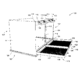
ease of filter change out, and with reliability for the environmental
application.
[0004] V-bank filters have been used in applications involving air
filtration in animal
confinement facilities where both large amounts of filtration media and high
air flow rates are
desired. A V-bank filter typically includes two or more pairs of panel
filters, for example,
where each pair of adjacent panel filters is arranged in a V-shaped
configuration. In these
applications, the panel filters typically include pleated filter media.
[0005] Embodiments of the present invention are directed toward
improvements over the
state of the art.
CA 2740466 2017-09-28
BRIEF SUMMARY OF THE INVENTION
[0006] In one aspect, embodiments of the invention provide a filter system
that includes a
housing having a generally rectangular inlet opening through one side thereof,
and an outlet
opening through a different side. The rectangular inlet opening is surrounded
by a generally
rectangular sealing surface. In an embodiment, the filter system also includes
a door having a
generally rectangular seating surface, with the seating surface surrounding a
through-port
opening. The door is movable between an open position and a closed position
relative to the
housing, and the through port opening is aligned with the rectangular inlet
opening when the
door is in the closed position. In at least one embodiment, the filter system
has a hinge
connecting the door to the housing, and the door pivots between open and
closed positions
about the hinge. Further, in certain embodiments, a generally rectangular
panel pre-filter is
seated along the rectangular seating surface of the door, and at least one V-
bank primary filter
is positioned in the rectangular inlet opening. In a particular embodiment,
the V-bank primary
filter has a generally rectangular peripheral flange in general alignment with
the generally
rectangular sealing surface. Further, the V-bank primary filter has a
plurality of filter media
sections projecting away from the peripheral flange and into the interior of
the housing. The
filter system further includes a latch having cooperating components between
the door and the
housing, such that the latch is adapted to keep the at least one generally
rectangular panel pre-
filter positioned inline and upstream of the at least one V-bank primary
filter. Additionally,
the filter system includes a seal between the generally rectangular peripheral
flange of the V-
bank primary filter and the generally rectangular sealing surface.
[0007] In another aspect, embodiments of the invention provide a filter
system that
includes a housing having an inlet opening and an outlet opening, and a V-bank
filter having a
flange configured to seat against a perimeter portion of the inlet opening,
and disposed
between the inlet and outlet opening. In an embodiment of the invention, the
filter system also
includes a pivoting door configured to move between an open position and a
closed position.
In the closed position, the door covers the inlet opening, and, in the open
position, the door
allows for the removal and installation of the V-bank filter. In a particular
embodiment, the
2
CA 2740466 2017-09-28
filter system further includes a panel filter disposed within the pivoting
door. The panel filter
is configured to pre-filter air entering through the inlet opening to the V-
bank filter.
[0008] In still another aspect, embodiments of the invention provide a
filter system that
includes a housing having an inlet opening and an outlet opening, and a V-bank
filter having a
flange configured to seat against a perimeter portion of the inlet opening. In
an embodiment,
the flange is disposed between the inlet and outlet opening. An embodiment of
the filter
system also includes a pair of cooperating retainers, including a first
retainer and a second
retainer on opposing sides of the outlet opening. Each retainer is generally
step-shaped, with a
mounting portion, a spacer portion and a retainer portion. The mounting
portion is mounted to
the housing, and the spacer portion spaces the retainer portion away from the
perimeter
portion in spaced relation to trap the flange of the V-bank filter therein. At
least one of the
retainers is movable to accommodate installation and removal of the V-bank
filter. In an
embodiment of the invention, a seal is disposed between the flange and the
perimeter portion
of the housing.
100091 In yet another aspect, embodiments of the invention provide a
replaceable V-bank
filter for use with a housing having an inlet opening and an outlet opening,
with the housing
having an outer upstream rectangular sealing surface and upper and lower
retainers defining
channels therein. An embodiment of the replaceable V-bank filter includes a
generally
rectangular frame having a peripheral and generally rectangular flange
surrounding an inlet, a
generally rectangular seal means along a first side of the flange for sealing
against the
rectangular sealing surface of the housing, and a generally rectangular seat
means along a
second side of the flange for seating against the upper and lower retainer. In
at least one
embodiment, the generally rectangular seat means is positioned, and has
sufficient depth, to
facilitate compression of the generally rectangular seal means relative to the
rectangular
sealing surface of the housing. This compression provides for said sealing
when employed in
the upper and lower retainers. An embodiment of the replaceable V-bank filter
has a plurality
of pleated panel filters. Each panel filter is supported by the generally
rectangular frame and
projects in a direction away from the flange. Further, pairs of the pleated
panel filters are
arranged in generally V-shaped configurations, with adjacent ends of adjacent
panel filters
3
CA 2740466 2017-09-28
being joined by bridging sections that extend transversely relative to two
opposed sides of the
generally rectangular frame.
[0010] Other aspects, objectives and advantages of the invention will
become more
apparent from the following detailed description when taken in conjunction
with the
accompanying drawings.
BRIEF DESCRIPTION OF THE DRAWINGS
[0011] The accompanying drawings incorporated in and forming a part of the
specification illustrate several aspects of the present invention and,
together with the
description, serve to explain the principles of the invention. In the
drawings:
[0012] FIG. 1 is a perspective view of a filter housing constructed in
accordance with an
embodiment of the invention;
[0013] FIG. 2 is a close up view of a portion of the filter housing of FIG.
1;
[0014] FIG. 3 is a perspective view of a door on the filter housing of FIG.
1, the door
including a lower retainer;
[0015] FIG. 4 is a perspective view of the filter housing of FIG. 1 with a
V-bank filter,
panel pre-filter, and door with protective grate;
[0016] FIG. 5 is a perspective view of a V-bank filter, constructed in
accordance with an
embodiment of the invention;
[0017] FIG. 6 is a perspective view of a single-header box filter,
constructed in
accordance with an embodiment of the invention;
[0018] FIG. 7 is an exploded view of a filter housing with a V-bank filter,
panel pre-filter,
and door with protective grate, according to an embodiment of the invention;
[0019] FIG. 8 is an exploded view of a filter housing with a V-bank filter,
panel pre-filter,
and door with protective grate, according to an alternate embodiment of the
invention;
4
CA 2740466 2017-09-28
[0020] FIG. 9 is a cross-sectional view of a filter system constructed in
accordance with
an embodiment of the invention;
[0021] FIG. 10 is an exemplary embodiment of a portion of an animal
confinement
facility with a plurality of filter systems constructed in accordance with an
embodiment of the
invention;
[0022] FIGS. 11-15 illustrate perspective views of various embodiments of a
molded
plastic filter housing, constructed in accordance with an embodiment of the
invention;
[0023] FIGS. 16-17 provide perspective views of molded plastic filter
housings according
to an embodiment of the invention in which the filter housings are nested;
[0024] FIG. 18 is a perspective view of an angled filter housing
constructed in accordance
with an embodiment of the invention;
[0025] FIG. 19 is a cross-sectional view of a molded plastic filter housing
with a molded
plastic door, constructed in accordance with an embodiment of the invention;
and
[0026] FIG. 20 is a perspective view of a filter system kit incorporating
filter housings
constructed in accordance with embodiments of the invention.
[0027] While the invention will be described in connection with certain
preferred
embodiments, there is no intent to limit it to those embodiments. On the
contrary, the intent is
to cover all alternatives, modifications and equivalents as included within
the spirit and scope
of the invention as defined by the appended claims.
DETAILED DESCRIPTION OF THE INVENTION
[0028] As shown in FIGS. 1-5 below, embodiments of the present invention
include a
filter housing with a pivoting door and a sliding latch that permit the quick
removal and
installation of two or more V-bank filter elements, but also facilitate an
airtight seal between
the housing and filter element. The novel filter housing configuration
described herein
simplifies the maintenance, provides for a practical and reliable filter
replacement process,
CA 2740466 2017-09-28
and, thus, and may lower the costs associated with the operation of animal
confinement
facilities.
[0029] FIG. 1 illustrates a filter housing 100 for use in an animal
confinement facility,
constructed in accordance with an embodiment of the invention. In the
embodiment shown,
the filter housing 100 is substantially box-shaped, and may be formed from
sheet metal or
other suitable material. Filter housing 100 has a front side 101, a top side
103, a bottom side
105, a rear side 107, and two lateral sides 111. The front side 101 of the
filter housing 100 has
two rectangular openings to provide inlets, 102, 104 separated by a divider
such as vertical
post 113, and each configured to accept a V-bank filter element (see FIG. 4).
The bottom side
105 has a large rectangular outlet opening 119 that is common to all of the
inlets. A flange
129 runs around a perimeter of the bottom side 105 of the filter housing 100.
In an
embodiment of the invention, the flange 129 has openings for fasteners, which
may be used,
for example, in the installation of the filter housing 100.
[0030] In embodiments of the inventions, the rear side 107 of the filter
housing is very
similar or identical to the front side 101 in terms of the inlet openings 102,
104, pivoting doors
106, 108, latching mechanisms, and filter elements employed. Therefore, for
the sake of
brevity, the following description of the filter housing 101 refers only to
the front side 101.
However, it should be noted that all of the features and elements shown and
describes with
respect to the front side 101 of the filter housing applies equally to the
rear side 107.
[0031] Filter housing 100 also includes two pivoting doors 106, 108
attached to the filter
housing 100 via hinges (shown in FIG. 9) located along the bottom side of the
two rectangular
openings 102, 104. However, as will be discussed below, it is also
contemplated that pivoting
doors could be hinged at the top side or on the lateral sides of the two
rectangular openings
102, 104. Each pivoting door 106, 108 has a rectangular frame 109 with a
seating surface 121
surrounding a through-port opening 115 in which the panel pre-filters may
nest. The seating
surface 121 may comprise a recessed region generally facing the V-Bank filter
when in the
close position. In at least one embodiment, the rectangular frame 109 supports
a protective
grate 117 along the seating surface 121 and across the through-port opening
115 such that the
door 106, 108 is capable of holding a panel pre-filter 136 (shown in FIG. 4).
Furthermore, in
6
CA 2740466 2017-09-28
at least one embodiment, the grate 117 comprises a wire mesh grate having a
plurality of
horizontal and vertical wires spaced far enough apart so as not to restrict
the flow of air
through the filter housing 100, but also to protect the filter media and
prevent the ingress of
large objects.
100321 FIG. 1 shows that along a top portion 112 of the front of filter
housing 100 there
are two latches 114, one disposed on each upper retainer 135. In an embodiment
of the
invention, each latch 114, or has a cooperating components on the
corresponding door 106,
108 in the form of a first L-shaped bracket 122. As will be explained more
fully below, the
latch 114 is configured to work with first L-shaped bracket 122 to secure the
doors 106, 108 in
the closed position. In an embodiment of the invention, the latch 114
comprises a second L-
shaped bracket 114.
100331 In the embodiment of FIG. 1, one portion of the latches 114 is
formed and secured
upon the upper retainer 135 on the housing, and an L-shaped bracket 122 on the
door. Each
upper retainer 135 may be step-shaped, as shown, and each includes two slots
116 (see
closeup view of FIG. 2 also), which facilitate vertical sliding adjustment and
movement,
which helps to facilitate installation and clamping of the V-Bank filter
elements 138 in
position. The slots 116 are configured such that a fastener can slide vertical
when unfastened -
such as a screw 118 (see closeup view of FIG. 2 also ¨ and realizing it screws
into a threaded
hole in housing) with a knob 120 (see closeup view of FIG. 2 also). The knob
120 is attached
at one end of the screw 118 to allow for manual adjustment can be inserted
through the slot
116 and assembled to a threaded hole in the filter housing 100. The length of
the slots 116
allows the upper retainer 135 to be moved up or down when the screws 118 are
loosened.
Also, the screw 118 is relatively long so that the upper retainer 135 can be
moved in
horizontally forward and away from the front of the housing 100 between
unclamped and
clamped positions. Thus, there are two axes of adjustment for V-bank
installation and
clamping ¨ both vertical and horizontal adjustment, which also allows the
upper retainer 135
to be pivoted or canted during installation to afford clearance for the upper
end of a V-bank
flange 142 and gaskets.
7
CA 2740466 2017-09-28
[0034] In an embodiment of the invention shown in FIG. 2, each upper
retainer 135 has a
mounting portion 123, a spacer portion 125, and a retainer portion 127. The
mounting portion
123 is attached to the top of the front side 101 of the housing 100 and
defines the slots 116.
The spacer portion 125 is configured to accommodate the flange 142 and gasket
seals of the
V-bank filter element 138. The retainer portion 127 is configured to keep the
aforementioned
V-bank flange 142 and associated gasket seals in sealing engagement with a
seating surface
144 (shown in FIG. 4) around the perimeter of the rectangular openings 102,
104 of the
housing 100. By manually actuating the knob 120, the V-bank filter element 138
can be
secured and sealingly clamped with axial compression in the gaskets against
the front seating
surface 144 of the housing 100, or can be loosened to facilitate release for
removal and
installation purposes. Actuating the knob 120 can also secure the panel pre-
filter 136 (shown
in FIG. 4) in the grate 117 by compressing the V-bank filter element 138
gaskets against the
panel pre-filter 136.
[0035] In a particular embodiment of the invention, the filter housing 100
includes a lower
retainer for each door 106, 108. Further, in at least one embodiment of the
invention, the
lower retainer is identical, or very similar to the upper retainer 135. FIG. 3
is a perspective
view of a portion of filter housing 100 that includes a lower retainer 170.
Similar to the upper
retainer 135, the lower retainer 170 may have a stepped profile and include a
mounting portion
172, a spacer portion 174, and a retainer portion 176. In FIG. 3, the retainer
portion 176 is
largely hidden by the rectangular frame 109 of door 106, 108. The lower
retainer 170 is
attached to the door 106 at a bottom side 178 of the rectangular frame 109 via
one or more
hinged plates 180. The one or more hinged plates may be attached to the bottom
side 178 of
the rectangular frame 109 by welding, brazing, soldering, or using a fastener
of some type.
The mounting portion 172 is attached to the bottom of the front side 101 of
the housing 100,
and, in the embodiment of FIG. 3, includes two slots 182 that allow for
vertical adjustment of
the door 106, 108 to facilitate changing of the V-bank filter 138 or the panel
pre-filter 136.
[0036] The slots 182 are configured such that a fastener can slide vertical
when
unfastened - such as a screw 118 (not shown in FIG. 3), which can be assembled
into a
threaded hole in filter housing 100 with a knob 120 (not shown in FIG. 3). The
knob 120 is
8
CA 2740466 2017-09-28
attached at one end of the screw 118 to allow for manual adjustment can be
inserted through
the slot 182 and assembled to a threaded hole in the filter housing 100. The
length of the slots
182 allows the lower retainer 170 to be moved up or down when the screws 118
are loosened.
Also, the screw 118 may be relatively long so that the lower retainer 170 can
be moved in
horizontally forward and away from the front of the housing 100 between
unclamped and
clamped positions. The lower retainer 170 is secured to the filter housing 100
such that the
screw 118 can be inserted through slot 182 and the knob 120 tightened against
the mounting
portion 172 to keep the door 106, 108 from moving. The spacer portion 174 is
configured to
accommodate the flange 142 and gasket seals of the V-bank filter element 138.
The retainer
portion 176 is configured to keep the aforementioned V-bank flange 142 and
associated gasket
seals in sealing engagement with a seating surface 144 (shown in FIG. 4)
around the perimeter
of the rectangular openings 102, 104 of the housing 100. By manually actuating
the knob 120,
the V-bank filter element 138 can be secured and sealingly clamped with axial
compression in
the gaskets against the front seating surface 144 of the housing 100, or can
be loosened to
facilitate release for removal and installation purposes. Actuating the knob
120 can also
secure the panel pre-filter 136 (shown in FIG. 4) in the grate 117 by
compressing the V-bank
filter element 138 gaskets against the panel pre-filter 136.
[0037] Referring again to FIG. 2, an embodiment of the invention is
illustrated in which
each pivoting door 106, 108 also includes a first L-shaped bracket 122
attached to a top side
124 of the pivoting door 106, 108. The first L-shaped bracket 122 has a hole
or opening 126
in a vertical portion 128 of the first L-shaped bracket 122. As stated above,
each upper
retainer 135 includes the latch 114, which in at least one embodiment is
second L-shaped
bracket 114 with a hole or opening 132 in a vertical portion 133 of the second
L-shaped
bracket 114. The opening 132 in each of the second L-shaped brackets 114
aligns with the
opening 126 in the corresponding first L-shaped bracket 122 such that a
locking bolt 134 can
be inserted through both openings 126, 132 to hold the pivoting door 106, 108
in the closed or
shut position. At least opening 132 is threaded, or potentially both openings
are threaded such
that locking bolt 134 having a threaded portion 157 (with a knob such as t-
handle) can be
selectively secured and released.
9
CA 2740466 2017-09-28
[00381 FIG. 4 illustrates the filter housing 100 of FIG. 1 with exemplary
filter elements
installed therein. Because the illustrated embodiment of the filter housing
100 is configured
with two similar openings, doors, upper retainers and latches, only one side
of the filter
housing 100 and corresponding filter elements will be described below, as the
description will
be the same for the other side of the filter housing 100. Pivoting door 108 is
shown with the
panel pre-filter 136 installed within the frame 109 of the pivoting door 108,
though in normal
operation, each pivoting door 106, 108 would have the panel pre-filter 136
installed therein.
When the door 106, 108 is in the open position and during movement to the
closed position
(with the hinge to the door at the bottom), the panel pre-filter 136 rests in
position via the
forces of gravity such that no additional clamping is even required and the
panel pre-filter 136
may be simply laid into the nesting position along the L shaped seating
surface 121 and easily
removed therefore as well. Further, one step securement of the pre-filter 136
is accomplished
with the latch 114 upon closure of the door 106, 108.
[0039] Further as an advantage, as can be seen in FIG. 4, one side of the
panel pre-filter
136 is protected by the grate 117 of the pivoting door 108, while the other
side of the panel
filter is positioned adjacent to a V-bank filter element 138 when the pivoting
door 108 is in the
closed position. In a particular embodiment, the generally rectangular panel
pre-filter 136 fits
loosely into the frame 109 of the pivoting door 108, and is secured in place
only when the
pivoting door 108 is closed. In an alternate embodiment, the panel pre-filter
136 is held in by
fastening and/or clip devices (not shown) disposed on the frame 109 of the
pivoting door 108,
or the panel filter may be press fit into the frame 109 of the pivoting door
108, and held in
place by friction.
[0040] When positioned upstream from the V-bank filter element 138 within
the frame
109 of the door 106, 108, the panel pre-filter 136 is configured to pre-filter
air entering into the
V-bank filter element 138 by removing relatively larger particles and dust
from the air stream,
for example, before those larger particles can enter the V-bank filter element
138. One effect
of the pre-filtering panel pre-filter 136 is to lengthen the useful life of
the V-bank filter
element 138. In some embodiments of the invention, the panel pre-filter 136
includes pleated
CA 2740466 2017-09-28
pre-filter media 137 housed within a rectangular paperboard frame 139.
Further, in certain
embodiments the panel pre-filter media 137 is rated at MERV 14 or lower.
[0041] Referring now to FIG. 5, which illustrates a perspective view of the
V-bank filter
element 138 constructed in accordance with an embodiment of the invention. The
V-bank
filter 138 comprises a series of panel filters 140 each having a frame 145
supporting a pleated
filter media 147 panel. In some embodiments of the invention the filter media
147 is pleated
and the frame 145 is constructed of a rigid material such as plastic, although
paperboard
frames are more common for pleated panel filter elements. The entire assembly
which
comprises the V-bank filter element 138 is supported by a frame having a
peripheral and
outwardly projecting rectangular flange 142, in which each panel filter 140 is
attached to the
adjacent panel filter 140 along a side edge 141, and the panel filters 140 are
angled such that
any two adjacent panel filters 140 come together in a V-shaped configuration.
In at least one
embodiment of the invention, adjacent ends or side edges 141 of adjacent panel
filters 140 are
joined by bridging sections 146 that extend transversely relative to two
opposed sides of the
edges of the flange 142. A top panel 153 and bottom panel 155 (also referred
to as end panels)
cover the top and bottom portions, respectively, of the V-bank filter element
138, and the
panels 153, 155 create a seal with each of the panel filters 140 such that air
flowing into the V-
bank filter element 138 must flow through the filter media 147. It is also
contemplated that
non-pleated filter panels may also be used to construct the V-bank filter
clement 138, such as a
collection of other panel filters arranged in a V-bank configuration.
[0042] The flange 142 may be formed from a rigid material such as a hard
plastic or
metal. In at least one embodiment, the flange 142 is integrally formed with
end panels 153,
155. A first seal 148 is disposed on a back surface 149 of the flange 142, and
a second seal
152 is disposed on a front surface 151 of the flange. The V-bank configuration
allows for
relatively high amount of filter media surface area per a given volume while
permitting a
reasonably high air flow rate through the filter assembly. This configuration
has proven
effective at sufficiently trapping certain airborne viruses that can affect
livestock held in
animal confinement facilities.
11
CA 2740466 2017-09-28
[0043] Referring again to FIG. 4, the V-bank filter element 138 is shown in
rectangular
openings 102, 104 of filter housing 100. As can be seen from FIG. 4, thc V-
bank filter
element 138 can be placed in the filter housing 100 such that the panel
filters 140 of the V-
bank filter are arranged either vertically or horizontally. In either
configuration, an airstream
flowing through the inlet openings 102, 104 of the filter housing, flows
through the V-bank
filter element media and out of the outlet opening 119 in the bottom side 105
of the filter
housing 100.
[0044] As explained above, the V-bank filter 138 includes the flange or
frame 142 along a
front side 143 (shown in FIG. 5) of the V-bank filter element 138. The flange
142 is
configured to seat against a perimeter portion, or seating surface, 144 of
rectangular opening
104. In the embodiment of FIG. 4, the flange 142 is generally rectangular and
is in general
alignment with the seating surface 144, and each of the plurality of panel
filters 140 projects
away from the flange 142 towards the interior of the filter housing 100.
[0045] In at least one particular embodiment of the invention, the V-bank
filter element
138 uses a MERV 16 filter media 147 (shown in FIG. 5). In an alternate
embodiment, the V-
bank filter element 138 uses a MERV 15 filter media, as determined by the
ASHRAE 52.2-
2007 standard. In another alternate embodiment of the invention, a HEPA filter
may be used
as the V-bank filter media. A I IEPA filter is configured to capture 99.97 of
all particles of 0.3
micron in size. Additionally, a near-HEPA filter, such as that sold under the
brand name
Micro Guard LR, which combines low resistance to airflow with efficiencies
above 99% for
0.3 micron particles may be used as a single-header box filter in place of the
V-bank filter
element 138.
[0046] FIG. 6 illustrates an exemplary single-header box filter 186, such
as might be used
in the aforementioned Micro Guard LR filter. The box filter 186 includes
cell sides 188,
which in at least one embodiment, are made from a rigid material, including
plastics, such as
high-impact polystyrene, or metal. In a particular embodiment, a flange 190,
made of the
same material as the cell sides 188, is attached on a front side of the box
filter 186 around the
perimeter of cell sides 188. In a particular embodiment, the media is molded
into pre-formed
channels that form the pleats. A pleated media pack 192 is attached, using an
adhesive for
12
CA 2740466 2017-09-28
example, on interior surfaces of the cell sides 188. In at least one
embodiment, the media
pack includes embossed pleats and is made from a synthetic, water-resistant
material whose
performance is substantially unaffected, other than a temporary rise in
airflow resistance, by
humidity and exposure to moisture levels reasonably expected to be found in
airstreams in
animal confinement facilities.
[0047] Similar to the V-bank filter 138, the single-header box filter 186
would be used
with a panel pre-filter 136 to remove large particulates and other
contaminants that could clog
or otherwise impair the performance of the box filter 186. Typically, pre-
filters used with box
filter 186 such as the Micro Guard LR filter will have efficiencies of MERV
8 or higher.
[0048] To understand why these filter medias are effective at trapping
airborne viruses
affecting agricultural livestock, it helps to know the particle size of some
typical viruses. For
example, there are several swine-specific disease agents that affect pigs and
hogs in animal
confinement facilities, such as mycoplasma whose particle size typically
ranges from 0.3
micron to 0.9 micron. Other swine-specific disease agents include the swine
influenza virus
whose particle size typically ranges from 0.080 micron to 0.120 micron, the
porcine
reproductive and respiratory syndrome virus (PRRSV) whose particle size
typically ranges
from 0.050 micron to 0.065 micron, and the porcine circovirus type 2 (PCV2)
whose particle
size typically ranges from 0.0017 micron to 0.0022 micron. Due to the small
particle size of
these viruses, high-efficiency filter medias are needed to filter these
particles from the air, or
from the small particles that carry these viruses through the air.
[0049] To ensure that all airflow through the filter housing 100 flows
through the panel
pre-filter 136 and V-bank filter 138, in an embodiment of the invention, the
first seal 148 is
disposed between the flange 142 of the V-bank filter element 138 and the
perimeter portion
(i.e. seating surface 144) of rectangular opening 104. In at least one
embodiment, the first seal
148 is substantially rectangular. Whereas, in at least one embodiment, the
flange 142 is made
from a rigid material such as a hard plastic or metal, the first seal 148 is
made from a
compliant gasket material, such as rubber, for example, urethane, plastisol,
nitrile or some
other synthetic material having similar rubber-like properties, for example
poron or neoprene,
such that the first seal 148 is capable of creating an airtight seal between
the seating surface
13
CA 2740466 2017-09-28
144 of rectangular opening 104 and the flange 142 of V-bank filter element
138. While the
seals are shown to be flat, 0-ring or other profiles known in the art may also
be employed;
and/or the seals may also be integrally formed on the frame/flange.
[0050] In certain embodiments of the invention, the second seal 152 is
disposed between
the flange 142 of the V-bank filter element 138 and the panel pre-filter 136
so as to create a
seal therebetween. This second seal 152 however is less critical as the V-bank
filter element
138 will also remove dust. Nevertheless, at least some sealing is desired at
this location so as
to route most if not all air first through the pre-filter. Whereas the first
seal 148 is configured
to seat against a side of the flange 142 facing the filter housing 100, the
second seal 152 is
configured to seat against a side of the flange 142 facing away from the
filter housing 100. In
an embodiment of the invention, the second seal 152 is substantially
rectangular and made
from a compliant gasket material, such as the above-mentioned poron or
neoprene for
example, described above with respect to the first seal 148. The second seal
152 also serve a
seating function as the second seal 152 cooperates with the first seal 148 and
the flange 142 to
provide enough depth and resiliency in the structure overall ensure sufficient
compression to
create an airtight seal when the screws 118 tighten the upper retainer 135
against the front side
of the housing. In embodiments of the invention, the first and second seals
148, 152 range
from 1/8-inch to one inch in thickness, though in preferred embodiments, the
thickness for
these seals 148, 152 is approximately 1/4 inch.
[0051] FIG. 7 shows an exploded view of the filter system of FIG. 4 with
the doors 106,
108 (with frames 109 and grates 117) detached from the filter housing 100 and
each of the
upper retainers 135 secured against the flange 142 of the corresponding V-bank
filter element
138. The first seal 148, disposed between the flange 142 and the seating
surface 144 (shown
in FIG. 4) of rectangular opening 102, 104 (shown in FIG. 1) is configured to
create a first
airtight seal, and the second seal 152 disposed between the flange 142 and the
panel pre-filter
136 (shown in FIG. 4) creates a second seal. As can be seen in FIG. 7, the
upper retainer 135,
which can be raised when screws 118 (shown in FIG. 2) are loosened to properly
seat the
flange 142 of the V-bank filter 138 against the first seal 148 which is seated
against seating
surface 144, and is in its lowest position as evidenced by the screws 118
being located at the
14
CA 2740466 2017-09-28
top of slots 116. When the screws 118 are tightened, the upper retainer 135
compresses the
second seal 152, flange 142, and first seal 148 against the seating surface
144 to securely hold
the V-bank filter 138 in place. The locking bolt 134 through first L-shaped
bracket 122 and
second L-shaped bracket 114 secures the door 106, 108 in the closed position
such that the
panel pre-filter 136 is substantially aligned with the second seal 152, which,
in turn, is seated
against the flange 142. In an embodiment of the invention, the configuration
of components
shown on the front side of housing 100 is duplicated on the back side, such
that the filter
housing 100 has four V-bank filter elements 138, four doors panel pre-filters
136, and four
hinged doors 106, 108.
[0052] FIG. 8
shows an exploded view of a more compact filter system than that shown in
FIG. 7, constructed in accordance with an alternate embodiment of the
invention. The
compact filter system of FIG. 8 is configured to hold two V-bank or single-
header box filters
as opposed to the four-filter housing shown in FIG. 7. The filter system of
FIG. 8 includes a
door 606 (with frames 609 and grates 617) detached from the filter housing 600
and an upper
retainer 635 secured against the flange 142 of the corresponding V-bank filter
element 138. A
first seal 648, disposed between the flange 142 and a seating surface 644 of
rectangular
opening 602 is configured to create a first airtight seal, and the second seal
652 disposed
between the flange 142 and the panel pre-filter 136 (shown in FIG. 4) creates
a second seal.
As can be seen in FIG. 8, the upper retainer 635, which can be raised when the
screws 118
(shown in FIG. 2) are loosened to properly seat the flange 142 of the V-bank
filter 138 against
the first seal 648 which is seated against seating surface 644, and is in its
lowest position as
evidenced by the screws 118 being located at the top of slots 616. When the
screws 118 are
tightened, the upper retainer 635 compresses the second seal 652, flange 142,
and first seal
648 against the seating surface 644 to securely hold the V-bank filter 138 in
place. The
locking bolt 134 through first L-shaped bracket 622 and second L-shaped
bracket 614 secures
the door 606 in the closed position such that the panel pre-filter 136 is
substantially aligned
with the second seal 652, which, in turn, is seated against the flange 142. In
an embodiment of
the invention, the configuration of components shown on the front side of
housing 600 is
duplicated on the back side of the filter housing 600, such that the filter
housing 600 has two
V-bank filter elements 138, twp doors panel pre-filters 136, and two hinged
doors 606.
CA 2740466 2017-09-28
100531 FIG. 9 shows a cross-sectional view of a filter system 162,
constructed in
accordance with an embodiment of the invention. The cross-sectional view of
FIG. 9
illustrates how the V-bank filter element 138 is held in the filter housing
100 via the flange
142 with a first seal 148 between the flange and housing 100, and with a
second seal 152
between the flange 142 and step-shaped upper retainer 135. A second step-
shaped lower
retainer 159 is shown along the bottom side of the door 108 just above a hinge
158 for the
door 108. Like the upper retainer 135, lower retainer 159 also includes a
mounting portion, a
spacer portion and a retainer portion, but it receives the lower portion of
the flange 142 of the
V-bank filter element 138 as opposed to the upper portion. Also, this lower
retainer 159 is
preferably permanently fixed along the bottom, such as being welded or
fastened in place
(although as similar adjustment means as for the upper retainer could be used
¨ slots and
fasteners). During installation or removal, the upper retainer 135 will be
loosened to allow for
clearance of the upper end of the V-Bank filter element 138. As a consequence,
the lower
portion of the flange 142, first seal 148, and second seal 152 can be wedged
and pivotably
installed (or removed) into the lower retainer 159 until the first seal 148
seats against the
seating surface 144 of the housing 100. As such, the spacing portion of the
lower retainer 159
is dimensioned just slightly smaller than the overall thickness of the V-bank
flange 142 and
gasket seals 148, 152 on either side.
[0054] It should be noted that the placement of the hinge 158 could just as
easily be
placed along the top side of the door 108, or along either lateral side of the
door 108.
However, as noted above, the bottom side mounting does provide an advantage of
gravitational retention of the panel pre-filter 136 during installation and
removal, avoiding
secondary securing means. As can be seen from FIG. 9, the filter system 162 is
configured
such that air can enter the filter system 162 through either the front side
101 or rear side 107
through panel filters 136 and V-bank filter elements 138 located on either
side. These air
streams exit the filter system 162 through the outlet opening 119.
[0055] FIG. 10 illustrates an exemplary embodiment of a portion of an
animal
confinement facility 160. The embodiment of FIG. 10 shows an attic portion of
animal
confinement facility 160 having a plurality of filter systems 162, constructed
in accordance
16
CA 2740466 2017-09-28
with an embodiment of the invention. Each of these exemplary filter systems
162 comprise
the filter housing 100 (shown in FIG. 7), V-bank filter elements 138 (shown in
FIG 4), and
panel filters 136 (shown in FIG. 7) described above. In the embodiment shown,
the filter
systems are installed through openings 163 in a floor 164 of the attic portion
such that the
filter systems 162 are visible in the ceiling (not shown) of that portion of
the animal
confinement facility 160 which houses the animals. It is contemplated that the
filter systems
162 are configured to be used in both positive pressure air filtration systems
and negative
pressure air filtration systems.
[0056] As FIG. 10 shows, an animal confinement facility 160 may require a
number of
these filter systems 162 to properly filter the air in those facilities. As
such, the ability to
quickly and easily replace the V-bank filter elements 138 and pre-filtering
panel filters 136,
afforded by embodiments of the present invention, can reduce the amount of
time needed to
maintain the filter system and result in significant cost savings when
compared to
conventional filtering systems in which the entire housing and all filter
elements therein are
replaced as a unit.
[0057] FIGS. 11-13 illustrate various embodiments of molded plastic filter
housings
constructed in accordance with embodiments of the invention. FIG. 11 shows a
molded filter
housing 200 with a lateral-side inlet opening 202 and a top-side inlet opening
204. Some
embodiments of molded filter housing 200 include an optional second lateral-
side opening
206. Each opening 202, 204, 206 is configured to accommodate a V-bank filter
element 138
(shown in FIG. 5) or single-header box filter 186 (shown in FIG. 6). Around
each opening
202, 204, 206 on the outside of the filter housing 200, there is a seating
surface 218 configured
to accommodate a V-bank flange 142 or the flange 190 of the box filter 186.
Molded filter
housing 200 further includes a bottom side outlet opening 208 through which
filtered air flows
out of the filter housing 200. In at least one embodiment, the molded filter
housing 200 has no
openings in the front side 210 or back side 212. Edges and corners for the
substantially box-
shaped filter housing 200 are rounded for safety and ease of handling. A
flange 214 runs
around a perimeter 216 at the base of the filter housing 200. In an embodiment
of the
17
CA 2740466 2017-09-28
invention, the flange 214 has openings for fasteners, which may be used, for
example, in the
installation of the filter housing 200.
100581 FIG. 12 illustrates a molded plastic two-filter housing 220,
according to an
embodiment of the invention. Two-filter housing 220 has a first lateral-side
inlet opening 222
and a second lateral-side inlet opening 224. The two-filter housing 220 has a
relatively small
footprint and can be installed in areas where space is limited. Each opening
222, 224 is
configured to accommodate a V-bank filter element 138 (shown in FIG. 5) or
single-header
box filter 186 (shown in FIG. 6). Around each opening 222, 224 on the outside
of the filter
housing 220, there is a seating surface 232 configured to accommodate a V-bank
flange 142 or
the flange 190 of the box filter 186. Molded two-filter housing 220 further
includes a bottom
side outlet opening 226 through which the filtered air flows out of the filter
housing 220.
Edges and corners for the substantially box-shaped filter housing 220 are
rounded for safety
and ease of handling. A flange 228 runs around a base perimeter 230 of the
filter housing 220.
In a particular embodiment of the invention, the flange 228 has openings for
fasteners, which
may be used, for example, in the installation of the filter housing 220.
10059] FIG. 13 illustrates a molded plastic filter housing 240, according
to an embodiment
of the invention. In a particular embodiment, filter housing 240 has the same
footprint as the
two-filter housing 220, allowing it to be used in spaces where square footage
is limited but has
enough vertical space to accommodate the increased height of filter housing
240. The filter
housing 240 has two stacked front-side inlet openings 242, 244 separated by a
first horizontal
divider 246, and two back-side inlet openings 248, 250 separated by a second
horizontal
divider 252. While the back-side inlet openings 248, 250 and second horizontal
divider 252
are not visible in FIG. 13, each is substantially similar to the inlet
openings 242, 244 and
divider 246 shown on the front side of filter housing 240. Each opening 242,
244, 248, 250 is
configured to accommodate a V-bank filter element 138 (shown in FIG. 5) or
single-header
box filter 186 (shown in FIG. 6). Around each opening 242, 244, 248, 250 on
the outside of
the filter housing 240, there is a seating surface 254 configured to
accommodate a V-bank
flange 142 or the flange 190 of the box filter 186. Molded filter housing 240
further includes
a bottom-side outlet opening 256 through which filtered air flows out of the
filter housing 240.
18
CA 2740466 2017-09-28
A flange 258 runs around a perimeter 260 at the base of the filter housing
240. In at least one
embodiment of the invention, the flange 258 has openings for fasteners, which
may be used,
for example, in the installation of the molded filter housing 300.
100601 FIG. 14 shows a molded filter housing 300 with two adjacent front-
side inlet
openings 302, 304 separated by a first vertical divider 306, and two back-side
inlet openings
308, 310 separated by a second vertical divider 312. While the back-side inlet
openings 308,
310 and vertical divider 312 are not visible in FIG. 14, each is substantially
similar to the inlet
openings 302, 304 and divider 306 shown on the front side of filter housing
300. Each
opening 302, 304, 308, 310 is configured to accommodate a V-bank filter
element 138 (shown
in FIG. 5) or single-header box filter 186 (shown in FIG. 6). Around each
opening 302, 304,
308, 310 on the outside of the filter housing 300, there is a seating surface
322 configured to
accommodate a V-bank flange 142 or the flange 190 of the box filter 186.
Molded filter
housing 300 further includes a bottom-side outlet opening 314 through which
filtered air flows
out of the filter housing 300. In at least one embodiment, the molded filter
housing 300 has no
openings in the lateral sides 316, or in top side 317. Edges and corners for
the substantially
box-shaped filter housing 300 are rounded. A flange 318 runs around a
perimeter 320 at the
base of the filter housing 300. In an embodiment of the invention, the flange
316 has openings
for fasteners, which may be used, for example, in the installation of the
molded filter housing
300.
[0061] Typically, when animal confinement buildings are retrofitted to add
filtering units,
already-existing air inlets in the ceiling have to be sealingly covered by the
new filter housing.
However, FIG. 15 illustrates an alternate embodiment of the molded plastic
filter housing of
FIG. 14 which can make such a retrofit easier to implement. The FIG. 15 molded
plastic filter
housing 350 includes a covering 352 for outlet opening 314, thus allowing for
the filter
housing 350 to be integrated with the building air inlet (not shown) into one
self-contained
unit providing better seal integrity during installation. In at least one
embodiment the
covering 352 comprises louvered panels. This type of integrated filter
housing/air inlet
configuration also provides advantages when compared to conventional filtering
units, in
terms of cost and ease of installation when used during initial construction.
19
CA 2740466 2017-09-28
[0062] FIG. 16 illustrates the molded filter housing 340 showing the
potential for the
nesting of multiple molded filter housings 340 such that the storage and
transportation of these
molded filter housings 340 may be more efficient than that for filter housings
which are not
nestable. In the embodiment of FIG. 16, filter housings 340 each have four
inlet openings
342, 344, 348, 350 capable of accommodating four V-bank filter elements 138
(shown in FIG.
5) or four single-header box filters 186 (shown in FIG. 6). Each filter
housing 340 has a
bottom-side outlet opening 354, which constitutes substantially the entire
bottom side of the
filter housing 340. Opening up the entire bottom side of the filter housing
340 facilitates the
aforementioned nestability. Other filter housing configurations may also be
nestable in this
fashion. For example, the two-filter housing 220 of FIG. 12 and the filter
housing 240 of FIG.
13 can be made such that the filter housings 220, 240 are nestable.
[0063] FIG. 17 illustrates an alternate embodiment of a molded filter
housing 400
configured to be nested with other molded filter housings 400. In the
embodiment shown in
FIG. 17, each molded filter housing 400 has two adjacent top-side inlet
opening 402, 404 and
further includes a bottom-side outlet opening 406. The filter housing 400 also
includes
rounded edges and corners. As can be seen in FIG. 17, in at least one
embodiment, molded
filter housing 400 has no inlet openings on the front, back, or lateral sides.
A flange 408 runs
around a perimeter 410 at the base of the filter housing 400. In an embodiment
of the
invention, the flange 408 has openings for fasteners, which may be used, for
example, in the
installation of the molded filter housing 400.
[0064] FIG. 18 is a perspective view of a four-filter angled filter housing
420, which may
be constructed of metal or molded plastic. In an embodiment of the invention,
the angled
housing 420 includes two front-side inlet openings 422, 424, two rear-side
inlet openings 426,
428 (not visible in FIG. 18), and a bottom-side outlet opening 430. The front-
side inlet
openings 422, 424 are separated by a first vertical divider 432, while the
rear-side inlet
openings 426, 428 are separated by a second vertical divider 434. In a
particular embodiment
of the invention, the angled filter housing further includes an angled box
portion 436 that rests
on a rectangular base 438. The rectangular base 438 is configured to cover a
rectangular space
between the ceiling beams and rafters in an animal confinement facility, for
example, where
CA 2740466 2017-09-28
the rectangular space includes one of the air vents for the facility. In an
embodiment, the
angled filter housing 420 includes a covering 440 for opening 430, similar to
that shown on
filter housing 350 (in FIG. 15). The covering 440 allows for the filter
housing 350 to be
integrated with the building air inlet (not shown) into one self-contained
unit providing better
seal integrity during installation. In at least one embodiment the covering
440 comprises
louvered panels.
[0065] The molded plastic filter housings of FIGS. 11-18 may be made by
rotational
molding or blow molding, as well as conventional injection molding techniques.
Rotational
molding and blow molding may be used to improve the uniformity of wall
thickness and to
reduce porosity in molded parts. Constructing these filter housings from
thermoplastic makes
the filter housing less susceptible to rust, corrosion and rot. Further, by
constructing the filter
housing a single molded piece with no assembly required, manufacturing of the
housings may
be faster and less expensive. Additionally, the molded filter housings have no
seams or leaks
associated therewith that would allow for the bypass of unfiltered air.
[0066] Another feature of molded filter housings, namely the smooth seam-
free interior
and round corners and edges, result in high flow-through rates for airstreams
flowing within
the housings. Furthermore, the rounded edges and corners allow for the
interior of the filter
housing to be more easily clean than many conventional filter housings, and
generally provide
fewer areas for bacterial growth than conventional filter housings. In
embodiments of the
invention, molded filter housings may include features that facilitate the
rapid assembly of
pivoting doors over the inlet openings, and of retaining mechanisms for
securing a V-bank
filter in the filter housings. FIG. 19 illustrates a cross-sectional view of a
filter housing 460
including a housing door 462 that could be employed on any of the molded
filter housings in
FIGS. 11-18.
[0067] In a particular embodiment, the housing door 462 is made from molded
plastic,
though in alternate embodiments, the housing door 462 is metal. The housing
door 462 has a
frame 464 configured to house a panel pre-filter 136. As shown in the
embodiment of FIG.
19, a bottom side of the housing door 462 includes a lower retainer 466, which
may have a
stepped shape and may be integrally molded into the housing door 462. In at
least one
21
CA 2740466 2017-09-28
embodiment, the lower retainer 466 is configured to assemble to a hinge 468,
which is
integrally molded into a lower portion on the front of the housing 460. A
lower clip 470
proximate the hinge 468 is molded into a lower portion on the front of the
housing 460, and an
upper clip 472 is molded into an upper portion of the housing 460 to secure
the V-bank filter
138 to the housing 460. In a particular embodiment, the molded plastic clips
470, 472 can be
deformed to allow the flange 142 of the V-bank filter 138 to seat against the
housing 460.
When released, the clips 470, 472 return to their normal position covering the
flange 142 and
holding the V-bank filter 138 in place. In an embodiment, a door latch 474
proximate the
upper clip 472 is integrally molded into the housing 460 and is configured to
receive a small
bar or rod 476 extending from a top side of the housing door frame 464. The
door latch is
configured to be deformable in an upward direction, in the orientation of FIG.
19, to allow the
housing door 462 to close. When the door latch 474 is released, it returns to
its normal
position and secures the housing door 462 in the closed position.
[0068] It is envisioned that any of the filter housings described herein
could be packaged
in kit form. In an embodiment, the filter kit would be configured such that
all of the filter kit
packaging would be designed to fit inside of the housing so as to reduce
freight costs
associated with the filters systems. FIG. 20 illustrates an exemplary
embodiment of a filter kit
500 packaged for shipment. In the embodiment of FIG. 20, six filter kits 500
are staged on a
pallet 502. In each filter kit 500, all filters, including V-bank or box
header filters along with
panel pre-filter, are stored in the filter housing (not shown). Thus, the box
containing the filter
kit 500 will have approximately the same dimensions as the filter housing.
This efficient use
of space results in lower shipping costs for users of the filter kits 500.
100691 The use of the terms "a" and "an" and 'the" and similar referents in
the context of
describing the invention (especially in the context of the following claims)
is to be construed
to cover both the singular and the plural, unless otherwise indicated herein
or clearly
contradicted by context. The terms "comprising," "having," "including," and
"containing" are
to be construed as open-ended terms (i.e., meaning "including, but not limited
to,") unless
otherwise noted. Recitation of ranges of values herein are merely intended to
serve as a
shorthand method of referring individually to each separate value falling
within the range,
22
CA 2740466 2017-09-28
unless otherwise indicated herein, and each separate value is incorporated
into the
specification as if it were individually recited herein. All methods described
herein can be
performed in any suitable order unless otherwise indicated herein or otherwise
clearly
contradicted by context. The use of any and all examples, or exemplary
language (e.g., "such
as") provided herein, is intended merely to better illuminate the invention
and does not pose a
limitation on the scope of the invention unless otherwise claimed. No language
in the
specification should be construed as indicating any non-claimed element as
essential to the
practice of the invention.
100701 Preferred embodiments of this invention are described herein,
including the best
mode known to the inventors for carrying out the invention. Variations of
those preferred
embodiments may become apparent to those of ordinary skill in the art upon
reading the
foregoing description. The inventors expect skilled artisans to employ such
variations as
appropriate, and the inventors intend for the invention to be practiced
otherwise than as
specifically described herein. Accordingly, this invention includes all
modifications and
equivalents of the subject matter recited in the claims appended hereto as
permitted by
applicable law. Moreover, any combination of the above-described elements in
all possible
variations thereof is encompassed by the invention unless otherwise indicated
herein or
otherwise clearly contradicted by context.
23
CA 2740466 2017-09-28