Note: Descriptions are shown in the official language in which they were submitted.
CA 02740897 2013-11-01
,
Agent's Ref. 1741P01CA
LEAF STRIPPER
Field of the Invention
[0001] The present invention relates to strippers. In particular,
the invention relates to
a leaf stripper.
Description of the Related Art
[0002] United States Patent No. 7,168,643 to Mercier discloses a leaf
stripper
machine having a grille frame below which is disposed a rotatable cutting
blade for
cutting leaves. The stripper includes a vane, as shown in Figure 6 of Mercier,
extending
from the blade and configured to create a vacuum for sucking leaves through
the grille
frame.
[0003] Canadian Patent No. 2,485,336 to Bonny et al. discloses a leaf
stripper
machine having a grille frame below which is disposed a rotatable knife for
cutting
leaves. The stripper includes a turbine configured to suck leaves through the
grille frame
and eject the leaves outwards and away from the stripper.
[00041 Each of the above machines may suffer disadvantages. For
example, the
machines may suffer the disadvantage of having plant parts and resin adhere to
the
cutting blades. In such cases this may inhibit the suctioning and cutting
ability and thus
operation of the machine. Such machines may need to be regularly cleaned and
it may be
relatively time-consuming to have to stop operation of the machine to clean
the blades
before continuing.
1
CA 02740897 2013-11-01
2
[0005] The use of blades per se may be dangerous if one's fingers
accidentally touch
the blades while the machine is in operation. The need to insert one's hands
into the
machine shown by Bonny et al. to where the turbine is located to further clean
the
machine of trapped leaves may render this operation very dangerous if someone
was to
turn power back on by accident. If an object such as a metal object is dropped
through the
grill, the blades might cut it and send shredded metal parts flying through
the air, yet
further increasing the risks of injury to the operator.
[0006] These machines may be relatively difficult to operate. For
example, the
operator may be required to rotate the plant along the grille with one hand
while putting
pressure on the plant with the other hand. The use of the turbine in the
machine shown in
Bonny et al. may cause a relatively large amount of noise, rendering it more
difficult for
the operator of the machine to hear or communicate.
[0007] These machines may be relatively onerous to maintain. The machine
shown in
Bonny et al. may have a checker plate and a collector bag connected to its
turbine, and
leaves may get trapped within the machine's checker plate. In such cases, the
collector
bag must be removed in addition to the checker plate in order to clear said
trapped leaves.
Blades need to be periodically sharpened and in such cases, the machines may
need to be
fully disassembled in order to access the blades.
[0008] The cutting and suctioning aspects of these machines require a
relatively large
number of parts.
[0009] Each of the above machines may be limited in their adjustability,
which may
otherwise be useful to accommodate different varieties of plant species whose
leaves are
to be stripped.
[0010] There is accordingly a need for a leaf stripper that overcomes
the above and
other disadvantages of the known prior art.
CA 02740897 2013-11-01
3
BRIEF SUMMARY OF INVENTION
[0011] The present invention provides a leaf stripper disclosed herein
that overcomes
the above disadvantages. It is an object of the present invention to provide
an improved
leaf stripper.
[0012] There is accordingly provided a leaf stripper for removing leaves
from a plant.
The leaf stripper includes a housing having an interior. The stripper has a
grille supported
by the housing and in communication with the interior. The grille is shaped to
selectively
enable the leaves to at least partially pass therethrough. The stripper has a
stripping motor
disposed within the interior of the housing and supported by the housing. The
stripper has
a rotatable, tension-adjustable string member operatively connected to the
stripping
motor. The string member is configured to create a partial vacuum within the
interior of
the housing for at least partially sucking the leaves through the grille when
rotated and to
at least partially shred the leaves at least partially passing through the
grille.
[0013] There is also provided a leaf stripper for removing leaves from a
plant. The
leaf stripper includes a housing having an interior, a top, a tumbler portion
adjacent the
top, a bottom opposite the top and a stripping portion disposed below the
tumbler portion.
The stripper has a grille disposed within the interior of the housing and
supported by the
housing. The grille is disposed between the tumbler portion and the stripping
portion. The
grille is shaped to selectively enable the leaves to at least partially pass
therethrough. The
stripper has a rotatable tumbler member disposed within the tumbler portion of
the
housing. The tumbler member is configured to tumble portions of the plant
around the
grille. The stripper has a stripping motor supported by the housing and
disposed in the
stripping portion of the housing. The stripper has a rotatable cutting member
connected to
the stripping motor. The cutting member is configured to create a partial
vacuum within
the stripping portion of the housing for causing the leaves to be at least
partially sucked
through the grille from the tumbler portion of the housing to the stripping
portion of the
housing when rotated. The cutting member is also configured to at least
partially shred
the leaves so at least partially sucked through the grille.
CA 02740897 2013-11-01
4
[0014] There is further provided a leaf stripper for removing leaves
from a plant. The
leaf stripper includes a housing having an interior, a top, a tumbler portion
adjacent the
top, a bottom opposite the top, an output opening extending through the
housing and a
stripping portion adjacent to the bottom. The stripper has a grille disposed
within the
interior of the housing and supported by the housing. The grille is disposed
in a generally
horizontal plane between the tumbler portion and the stripping portion of the
housing.
The grille is shaped to selectively enable the leaves to at least partially
pass therethrough.
The output opening is aligned with the grille and the tumbler portion of the
housing. The
stripper has a tumbler motor mounted to the top of the housing. The stripper
has a
rotatable, radially extending, elongate tumbler member operatively connected
to the
tumbler motor and disposed within the interior of the housing. The tumbler
member has
at least one aperture extending therethrough. The tumbler member is configured
to
tumble portions of the plant around the grille. The stripper has a stripping
motor
supported by the housing and disposed in the stripping portion of the housing.
The
stripper has a motor cooling fan connected to the stripping motor. The motor
cooling fan
is configured to cool the stripping motor. The stripper has a rotatable,
flexible
monofilament line operatively connected to the stripping motor. The flexible
monofilament line is configured to create a partial vacuum within the
stripping portion of
the housing for causing the leaves to be at least partially sucked through the
grille from
the tumbler portion of the housing to the stripping portion of the housing
when rotated.
The flexible monofilament line is also configured to shred the leaves. The
stripper has an
output gate covering the output opening and through which portions of the
plant that are
at least partially removed of leaves may be retrieved.
BRIEF DESCRIPTION OF DRAWINGS
[0015] The invention will be more readily understood from the following
description
of preferred embodiments thereof given, by way of example only, with reference
to the
accompanying drawings, in which:
Figure 1 is a perspective view of a leaf stripper according to a first
embodiment;
CA 02740897 2013-11-01
Figure 2 is an exploded, disassembled perspective view of the leaf stripper
shown in
Figure 1;
5 Figure 3 is a cross-sectional, partially broken-away elevation view of
the top of the
housing of the leaf stripper of Figure 1, a tumbler portion of the housing
shown partially
broken away and fitted with the top of the housing, and a hinged gate of the
stripper
shown in more detail;
Figure 4 is an elevation view of the top of the housing of the stripper, the
interior of part
of the housing, a grille, a tumbler motor partially broken away and a
plurality of tumbler
members of the leaf stripper shown in Figure 1, with the tumbler portion of
the housing
being removed;
Figure 5 is an exploded, disassembled, partially simplified elevation view of
a grille,
string members, a stripping motor, and a height adjustment mechanism of the
leaf stripper
shown in Figure 4, as well as a flange of the housing shown in cross-section;
Figure 6 is an assembled, partially simplified view of the grille, the string
members, the
stripping motor, and the height adjustment mechanism of the leaf stripper
shown in
Figure 5, as well as the flange of the housing shown in cross-section;
Figure 7 is an assembled, partially simplified view of the grille, the string
members, the
stripping motor, and the height adjustment mechanism of the leaf stripper
shown in
Figure 6, with the distance between the string members and the grille being
reduced
relative to that shown in Figure 6;
Figure 8 is a top plan view of a hub upon which the string members shown in
Figure 5 are
mounted;
CA 02740897 2013-11-01
6
Figure 9 is an elevation view of the hub shown in Figure 8 with some of the
string
members connected thereto;
Figure 10 is a fragmentary, cross-sectional elevation view of the leaf
stripper of Figure 1,
showing the tumbler portion, an outlet gate and a chute of the leaf stripper;
Figure 11 is an elevation view of the top of a housing of a leaf stripper, the
interior of part
of its housing, a grille, a tumbler motor in fragment and a plurality of
tumbler members
according to a second embodiment, with the tumbler portion of the housing
being
removed;
Figure 12 is a top plan view of the grille and tumbler members shown in Figure
11;
Figure 13 is an end elevation view of one of the tumbler members shown in
Figures 11
and 12;
Figure 14 is a top plan view of a grille and a tumbler member connected
thereto
according to a third embodiment;
Figure 15 is an end elevation view of the tumbler member shown in Figure 14;
and
Figure 16 a side elevation view of a tumbler member and a grille in cross-
section
according to a fourth embodiment.
DESCRIPTION OF THE PREFERRED EMBODIMENTS
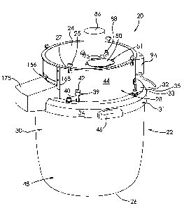
100161 Referring to the drawings and first to Figure 1, there is shown a
leaf stripper
20 for removing leaves from a plant. The leaf stripper has a housing 22. The
housing is
generally cylindrical and made of PVC in this example, with an interior 23 as
shown in
Figure 2, a closed top 24 and bottom 26 opposite the top. Housing 22 has a
tumbler
CA 02740897 2013-11-01
7
portion 28 adjacent the top 24. Referring to Figure 1, top 24 connects to the
tumbler
portion 28 via pivotable fasteners 25, which are connected to and extend from
the tumbler
portion 28. The fasteners may be actuated to selectively engage peripheral
grooves 27 of
the top 24. Put another way, the fasteners may be flipped upwards so as to
engage with
the grooves 27 and readily lock the top 24 in place.
[0017] Housing 22 includes a stripping portion 30 adjacent to and
disposed below the
tumbler portion 28. The housing includes a flange 31, as shown in Figures 1
and 2,
interposed between tumbler portion 28 and stripping portion 30. The flange has
a top 32
facing and extending around tumbler portion 28, with a plurality of radially
spaced-apart
apertures 33 extending therethrough. Flange 31 has an annular side 34 and an
angled wall
35 interposed between and connecting together top 32 and side 34. Referring to
Figure 2,
wall 35 is configured to rest upon and engage with exterior end 36 of the
stripping
portion 30. Flange 31 also has an annular shoulder 37 offset relative to top
32 and upon
which the tumbler portion 28 rests and engages. The flange 31 has a central
opening 38,
which shoulder 37 encircles.
[0018] As shown in Figure 1, the flange 31 also connects to the tumbler
portion 28
via pivotable fasteners 39. The fasteners are connected to and extending from
the flange
31. Fasteners 39 may be actuated to selectively engage apertures 40 of
brackets 42.
Brackets 42 are in the form of wire loops and are connected to and extend from
the
exterior 44 of the tumbler portion 28. The fasteners may be flipped upwards to
engage
brackets 42 and readily lock flange 31 to tumbler portion 28 of the housing.
The leaf
stripper may thus be used as a work station without the tumbler portion 28,
and parts
connected thereto, if desired by the operator. The fasteners of the leaf
stripper ensure that
the stripper may be easily and quickly dismantled for cleaning.
[0019] Housing 22 includes handles 46 extending outwards from the side 34
of flange
31 for selectively removing the flange and tumbler portion of the housing from
the
stripping portion of the housing. The housing further includes a cylindrical-
shaped
composting portion 48 adjacent to the housing's bottom 26. The composting
portion is
CA 02740897 2013-11-01
8
configured to collect partially shredded leaves and promote composting of the
partially
shredded leaves.
[0020] As shown in Figure 2, the leaf stripper 20 includes a feed
opening 49
extending through the top 24 of the housing. Plants whose leaves are to be
removed may
be selectively inserted through the opening 49 upon a feeder cover, in this
example, a
hinged gate 50, being opened. The gate is mounted to the top 24 via bolts 51.
As shown
in Figure 3, gate 50 has a protruding collar 52 disposed within the interior
23 of the
housing 22. The collar is configured to deflect eddy currents downwards, as
indicated by
the arrow of numeral 54, which causes plant material disposed adjacent to the
top 24 of
the housing to be propelled downwards.
[0021] As best shown in Figure 4, leaf stripper 20 has a plurality of
rotatable, radially
extending and spaced-apart, elongate tumbler members 56 disposed within the
tumbler
portion 28 of the housing and disposed within the interior 23 of the housing.
There are
four tumbler members in this example, as best shown in Figure 2, each of which
has a
rectangular, panel-like shape and a length approximately equal to the radius
of the grille
96. The tumbler members are configured to tumble the plant around and within
the
tumbler portion 28 of the housing. Referring back to Figure 4, each tumbler
member 56
has a first end 58 adjacent to the top 24 of the housing and a second end 60
opposite the
first end. The second end 60 is adjacent to the stripping portion 30 of the
housing shown
in Figure 2.
[0022] Each tumbler member 56 has at least one aperture and in this
example has a
pair of triangular-shaped or Christmas-tree-shaped apertures 62. The apertures
62 are
shaped to selectively enable portions of the plant to pass therethrough. The
apertures have
first ends 64 disposed adjacent to the stripping portion 30 of the housing and
second ends
66 opposite thereof The apertures are wider at their first ends 64 relative to
their second
ends 66. Apertures 62 include intermediate sections 68 interposed between and
wider
than ends 64 and 66. The tumbler members have lobe portions 70 disposed
between and
adjacent to end 64 and section 68. The lobe portions are shaped to deflect and
tumble the
CA 02740897 2013-11-01
9
plant upwards relative to Figure 4. Triangle-shaped portions 72 of the tumbler
member 56
between and adjacent to section 68 and end 66 are tapered outwardly towards
end 58 of
the tumbler member and are configured to deflect and tumble the plant
downwards
relative to Figure 4.
[0023] The tumbler members 56 in this example are made of rubber and are
connected together and held in place via a frame 74. The frame has a plurality
of radially
extending, elongate bars 76 configured to connect with the first ends 58 of
respective
ones of the tumbler members 56 via rivets 78. The bars 76 connect to a
centrally disposed
hub 80. Hub 80 has a central aperture 84.
[0024] Referring back to Figure 1, the leaf stripper 20 includes a tumbler
motor 86
mounted to the top 24 of the housing 22 via bolts 88. Referring to Figure 4,
the tumbler
members 56 are mounted to the motor 86. In particular, shaft 90 of the tumbler
motor is
disposed within aperture 84 of the hub 80 and fixed in place via a set screw
92 configured
to pass through the hub and engage shaft 90. The tumbler members 56 are thus
releasably
connected to the tumbler motor 86.
[0025] As shown in Figure 1, the leaf stripper 20 includes a power and
speed
controller or tumbler-member speed adjusting means 94 for controlling the
speed at
which the motor 86 rotates the tumbler members 56. In this case, the speed of
the motor
is adjusted by adjusting the current or voltage fed to the motor, though this
is not strictly
required and other ways of adjusting motor speed are possible. Controller 94
is
conventional and incorporates off-the shelf components. The controller
provides speed
control, and has a plastic casing from Kraloy I'm Canada, a 2.5 amp unit
disposed therein
from CanarmTM and a DaytonTM model capacitor disposed therein. Controller 94
will
therefore not be described in further detail.
[0026] As seen in Figure 2, the leaf stripper includes grille 96. The
grille is supported
by the housing 22 and is disposed within interior 23 in a generally horizontal
plane. Grille
96 is disposed between the top 24 and the bottom 26 of the housing 22 and, in
particular,
CA 02740897 2013-11-01
is disposed between the housing's tumbler portion 28 and stripping portion 30,
as shown
in Figure 10. Referring back to Figure 2, the grille is configured to cover
opening 38 of
the flange 31. Grille 96 has an annular peripheral portion 97 which abuts
against shoulder
37 of the flange 31. Thus, the grille is shaped and configured such that plant
matter
5 located within the tumbler portion 28 must pass through the grille in
order to enter the
stripping portion 30 of the housing.
[0027] Grille 96 has a plurality of spaced-apart, connected together
annular bars 98
that are concentric with one another. The annular bars are connected together
by a
plurality of spaced-apart, radially extending elongate bars 100 which overlay
annular bars
10 98. The elongate bars are configured to deflect plant parts upwards.
Thus, when flowers,
for example, hit one of the elongate bars 100, the flowers are turned around
on the grille
96, and the tumbler members 56 turn the flowers yet further again until the
flowers hit yet
another of the elongate bars, where the process repeats. Grille 96 is shaped
to selectively
enable leaves to at least partially pass therethrough while preventing an
operator's fingers
from passing therethrough. The grille is also shaped to inhibit buds, hops and
the like,
that the operator wants to isolate, from passing through the grille. Referring
to Figure 4,
the tumbler members 56 are shaped such that their second ends 60 abut the
grille 96.
[0028] As seen in Figure 2, the leaf stripper 20 includes a plurality of
cutting
members, in this example a plurality of rotatable, radially spaced-apart
string members
101. In this example, each of the string members is a flexible monofilament
line, though
this is not strictly required. The string members 101 are disposed within the
stripping
portion 30 of the housing, and, as shown in Figure 6, the string members are
disposed
adjacent to, spaced-apart from and below the grille 96, from the perspective
of Figure 6.
Referring to Figure 9, each string member has a first end 102 and a second end
103
opposite thereof Each string member has a radially outwardly extending
protrusion 104
at end 103. There may be between two to eight string members according to one
preferred embodiment, though this range is not intended to be limiting, and in
this
example there are eight string members as best shown in Figure 2. As the
number of
CA 02740897 2013-11-01
11
string members 101 is increased, so too will be increased the extent of
suction caused by
the string members for sucking leaves downwards.
[0029] The leaf stripper 20 has a hub 106 upon which the string members
are
mounted, as best shown in Figures 8 and 9. The hub has an annular shape and
comprises
a peripherally-disposed annular flange 107 and a central cylindrical connector
portion
108 extending outwards therefrom. A central aperture 109 extends through
flange 107
and connector portion 108. Hub 106 has a plurality radially spaced-apart
apertures 110
extending through connector portion 108. There may be between two to eight
apertures
110 according to one preferred embodiment, though this is not strictly
required, and in
this example the hub has eight apertures 110. The apertures are shaped to
enable ends 102
of the string members 101 to pass therethrough and to inhibit protrusions 104
from
passing therethrough. Each of the string members 102 connects to the hub, with
protrusions 104 abutting portions of the connector portion 108 adjacent to
apertures 110,
and extends through and radially outwards from respective ones of the
apertures 108 of
the hub. As the string members are rotated radially, centrifugal force biases
the string
members outwards and away from the hub 106 and the string members are thus
held in
place via protrusions 104.
[0030] Referring back to Figure 2, the leaf stripper 20 has a stripping
motor 112
disposed within the stripping portion 30 of the housing within interior 23 and
supported
by the housing 22. Referring to Figure 5, the stripping motor includes a shaft
114. The
string members 101 are connected to stripping motor 112 via the hub 106, which
operatively receives and connects with shaft 114 via the hub's aperture 109
shown in
Figure 8. A nut 116 is used to secure the hub 106 in place in this example by
threadably
connecting to shaft 114.
[0031] Advantageously, the string members 101, as rotated by the stripping
motor
112, are configured to create a partial vacuum within the interior 23 of the
housing 22 for
at least partially sucking the leaves 175 as shown in Figure 6 through the
grille 96 from
the tumbler portion to the stripping portion 30 of the housing. The string
members may
CA 02740897 2013-11-01
12
thus be referred to as a vacuum means. The string members 101 are also
configured to at
least partially shred the leaves at least partially passing through the grille
96. The string
members may never need cleaning because plant parts and/or resin does not
attach to the
string members.
[0032] Referring now to Figure 2, the leaf stripper 20 has a power and
speed
controller or string-member speed adjusting means 117 for controlling the
speed at which
the stripping motor 112 rotates the string members 101. The speed of the motor
is
adjusted by adjusting the current or voltage fed to the motor, though this is
not strictly
required and other ways of adjusting motor speed are possible. Controller 117
is
conventional and incorporates off-the-shelf components. In this example, it is
a Speed
Master (trademark) model having dial router speed control with a fuse and it
may be
purchased at hydroponic shops in Quebec, Canada. Controller 117 will therefore
not be
described in further detail.
100331 As the speed with which the string members rotate increases, the
string
members become relatively stiffer. Put another way, as the speed at which the
motor
rotates the string members increases, the string members become more rigid due
to
centrifugal force. Thus, by reducing the speed of rotation, advantageously,
the relative
stiffness and tension of the string members may be reduced as desired, which
may be
particularly useful for removing plant crops from more fluffy plants, the
string member
thus being tension-adjustable. This is in contrast to leaf strippers of the
known prior art
that use blades, where the stiffness and rigidity of the blades may remain the
same
regardless of the speed with which the blades rotates. Thus, the use of
machines using
blades may render it difficult to selectively remove leaves from plants that
are very fluffy,
for example, without also losing the plant's crop.
[0034] The leaf stripper 20 also has a motor cooling fan 118 that is
radially outwardly
extending. The motor cooling fan includes a closed top 120 facing the grille.
As shown in
Figure 6, the string members 101 are spaced-apart from and disposed between
the grille
96 and the closed top 120 of the motor cooling fan 118. Referring back to
Figure 2, the
CA 02740897 2013-11-01
13
top 120 of the fan is configured to inhibit interaction between the motor
cooling fan 118
and leaves passing through the grille 96. The motor cooling fan also includes
a plurality
of radially extending and spaced-spaced-apart vanes 122 configured to cool the
stripping
motor 112 as the motor rotates. Referring to Figure 5, motor cooling fan 118
is connected
to shaft 114 of the motor via collar 124. As seen in Figure 6, the fan is
interposed
between flange 107 of the hub 106 and motor 112 in this example. A washer 126
shown
in Figure 5 is disposed between hub 106 and fan 118. The manner in which and
parts
with which the hub and motor cooling fan connect to the motor are well known
and
conventional and therefore will not be described in further detail.
[0035] The leaf stripper 20 has a height adjustment mechanism 127. The
height
adjustment mechanism includes a stripping motor mount 128, as best shown in
Figure 2.
The stripping motor mount is generally cross-shaped in this example. Stripping
motor
mount 128 has a central portion 130 with an aperture 132 centrally extending
therethrough. Referring to Figure 5, motor 112 connects to the central portion
of the
mount 128 via bolts 136 and nuts 138 in a conventional manner, such that shaft
114 of
the motor coaxially aligns with and extends through aperture 132 of the mount.
As best
shown in Figure 2, the leaf stripper 20 includes a motor shield in this
example comprising
a pair of u-shaped brackets 140 having a cross-shaped end 142 configured to
receive the
motor 112 and an open end 144 configured to threadably connect to the central
portion
130 of the mount 128 via apertures 146 of the mount.
[0036] The stripping motor mount 128 has a plurality of radially spaced-
apart arms
134 extending outwards from the central portion 130. The arms each have a
proximal end
148 adjacent to the central portion 130 and a distal end 150 spaced-apart from
the end
148. As shown in Figure 5, each arm 134 has an aperture 152 extending
therethrough
adjacent to its distal end 150. Arms 134 are shaped such that apertures 152
align with
apertures 33 of the flange 31.
[0037] The height adjustment mechanism 127 includes a pair of threaded
members,
in this example, bolts 154. The bolts 154 have hexagonal apertures 156 at
their heads
CA 02740897 2013-11-01
14
158. Mount 128 threadably connects to flange 31 via the bolts 154 and nuts 156
disposed
within apertures 152 of the mount 128. The nuts are connected to the mount 128
via
welding in this example.
[0038] The height adjustment mechanism 127 further includes spacer
sleeves 160
made of polyethelene cushions in this example and elastomeric sleeves, in this
example,
rubber sleeves 162, adjacent thereto. The sleeves 160 and 162 are configured
to enable
the bolts 154 to extend therethrough respectively. The sleeves are at least
partially
disposed between the grille 96 and the motor mount 128. Rubber sleeves 162 are
configured to bias the string members 101 away from the grille. The rubber
sleeves are
also configured to bulge outwards as the string members 101 are brought closer
to the
grille 96 by tightening the bolts 154, as shown in Figure 7.
[0039] Thus, with reference to Figures 6 and 7, the height adjustment
mechanism 127
is configured such that adjustment of the bolts 154, in this example via a hex
or Allen key
164 engaging apertures 156, adjusts the height h between the top of the string
members
101 and the bottom of the grille 96. Height h1 shown in Figure 6 is greater
than height h2
shown in Figure 7, which shows the rubber sleeves 162 in their bulging
outwards state.
Advantageously, this allows the operator to optimize the cutting and
suctioning functions
of the leaf stripper as desired. For example, the height adjustment mechanism
advantageously enables the operator to selectively isolate crops that from
plants that are
very hard, very soft or very fluffy. In one preferred embodiment, height h is
equal to 118th
of an inch.
[0040] Referring now to Figures 2 and 10, the leaf striper 20 includes
an output
opening 176 extending through the tumbler portion 28 of the housing. The
output
opening is aligned with and is disposed above the grille 96. Output opening
176 is also
aligned with the tumbler portion 28 of the housing. The leaf stripper 20 has
an output gate
166 for retrieving portions of the plant that have leaves at least partially
removed upon
the gate being opened. The output gate in this example is a sliding gate
slidably mounted
to the tumbler portion 28 of the housing via a pair of spaced-apart rails 168.
Referring to
CA 02740897 2013-11-01
Figure 10, the gate 166 has a handle 170 and is moveable from an open position
172,
shown in broken lines, to a closed position 174. The gate 166 is configured to
selectively
cover the opening 176. When the gate 166 is in the open position 172, the
operator may
retrieve portions of the plants that are at least partially removed of leaves
from the leaf
5 stripper. The gate 166 in its closed position 174 inhibits parts of the
plant disposed within
the leaf stripper 20 from exiting therefrom via the opening 176. The leaf
stripper includes
a removable chute 178 configured to connect with portions of the housing 22
adjacent to
the opening 176. Parts of the plant stripped of leaves pass through the chute
178. A
bucket or container may be disposed below the chute to collect these parts of
the plant
10 stripped of leaves.
[0041] In operation and referring to Figures 2 and 6, when a plant 171,
shown in
Figure 6, is inserted through opening 49 to the tumbler portion 28 of the
housing, it is
tumbled around by the tumbler members 56. Gate 166 shown in Figure 10 is in
its closed
position. Referring to Figure 6, the string members 101 create a suction which
causes
15 parts 173 of the plant's leaves 175 to at least partially pass through
the grille 96 and get
cut by the string members. Leaf portions 177 so cut fall via gravity to the
composting
portion 48 of the housing shown in Figure 1, which enables these portions 177
of the
plant to slowly compost. The speed at which the tumbler members 56 and string
members
101 rotate may be adjusted via controllers 94 and 117, respectively, shown in
Figure 2.
The plant continues to be tumbled, with the shape of the tumbler members 56 as
well as
the shape of collar 52 of the gate 50, shown in Figure 3, causing plant
portions to tumble
around within the tumbler portion 28. The operator may periodically look
within the leaf
stripper by opening gate 50, for example, to gauge the progress of the leaf
stripping. Once
the operator is satisfied with the extent of leaf stripping, gate 166 is
opened and crop
portions 179 of the plant shown in Figure 6, such as buds, herbs, hops, and/or
other such
flowers, now largely stripped of leaves, tumble out of the stripper.
[0042] Figures 11 to 13 show part of a leaf stripper 20.1 according to a
second
embodiment. Like parts have like numbers and function as the embodiment shown
in
Figures 1 to 10 with the addition of ".1". Leaf stripper 20.1 is substantially
the same as
CA 02740897 2013-11-01
16
the leaf stripper 20 shown in Figures 1 to 10 with the exception of its
tumbler
arrangement. Tumblers 56.1 are relatively narrow and are primarily disposed
adjacent to
grille 96.1. The tumblers each comprise two parts: an elastomeric part in this
example an
elongate rubber member 180 and a rigid part, in this example an elongate UHMV
poly
alloy member 182, connected together via plurality of rivets 184 as shown in
Figures 12
and 13. Each of the members is rectangular and blade-like in shape. As seen in
Figure 13,
rubber members 180 in cross-section each have a curved upwardly sloping
portion 181
which causes portions of the plant hitting the tumbler members 56.1 to be
lifted upwards.
Referring to Figure 12, each of the rubber members 180 is connected to the top
186 of the
hub 80.1 via a respective connector tab 187 and rivet 188. The rubber members
are
configured to lift plant portions upwards from below and their shape and
rubber material
are configured to ensure that the plant portions are tumbled relatively softly
so as to
inhibit damage to the non-leaf parts of the plant. Alloy members 182 are
connected to the
bottom 189 of the hub 80.1, shown in Figure 11, via rivets 190. As shown in
Figure 13,
each alloy member 182 has a tapered edge 192 configured to deflect and lift
plant parts
such as flowers upwards. As shown in Figure 12, each of the edges 192 has a
wider end
195 disposed adjacent to the annular peripheral portion 97.1 of the grille and
a narrow
end 197 disposed adjacent to the hub 80.1 or center of the grille. This causes
the flowers
to be gently turned on the grille such that the flowers are raised above the
rubber
members 180 without having any rubber passing on top of the flowers.
[0043] Sloping portions 181 of the rubber members and edges 192 of the
alloy
members are spaced-apart and are opposite to each other in this example.
Tumblers 56.1
thus provide a double action of lifting and gently tumbling the plant, which
may be ideal
for hop flowers, for example.
[0044] Referring to Figure 11, shaft 193 extends through central aperture
84.1 of the
hub 80.1 and is secured to the hub by a set screw 192. Shaft 193 also connects
to shaft
90.1 of the tumbler motor 86.1 via a collar 196 and a pair of set screws 198
and 200.
CA 02740897 2013-11-01
17
[0045] Figures 14 and 15 show a leaf stripper 20.2 according to a third
embodiment.
Like parts have like numbers and function as the embodiment shown in Figures 1
to 10
with the addition of ".2". Leaf stripper 20.2 is substantially the same as
leaf stripper 20
shown in Figures 1 to 10 with one exception being that it does not include a
tumbler
motor. Rather, leaf stripper 20.2 has a single tumbler member 56.2 that is
connected to
the grille 96.2 via a plurality of bolts 204 that pass through a plurality of
apertures
extending through grille 96.2 and threadably connect with nuts 202. The
tumbler member
56.2 comprises a plurality of spaced apart teeth 205 each having a bent
portion 206 that
extends upwards from the perspective of the stripper and Figure 15. The teeth
also extend
towards the center of the grille 96.2 as shown in Figure 14. The tumbler 56.2
is
configured to deflect and tumble plant parts upwards. Stripper 20.2 is
manually operated
in part, with the operator passing parts of the plant through the tumbler
member 56.2,
while the string members and stripping motor, similar to those shown in
Figures 2 and 5
to 7, continue to operate.
[0046] Figure 16 shows a leaf stripper 20.3 according to a fourth
embodiment. Like
parts have like numbers and function as the embodiment shown in Figures 14 and
15 with
numeral ".3" replacing numeral ".2" and being added where the numeral did not
previously include a decimal extension. Leaf stripper 20.3 is substantially
the same as
leaf stripper 20.2 shown in Figures 14 and 15 with the exception that the
tumbler member
has a comb-like shape with a plurality of spaced-apart curved teeth 205.3.