Note: Descriptions are shown in the official language in which they were submitted.
CA 02741267 2011-05-27
AIR DISTRIBUTION FOR AN AIR SEEDER
This invention is in the field of agricultural air seeders and in particular
an air distribution
apparatus with valves on the ports to control product distribution and an
exhaust to
maintain critical velocity of the air stream.
BACKGROUND
Agricultural air seeders include generally an implement frame and a plurality
of furrow
openers spaced across a width of the frame, and movable to a lowered operating
position
where the furrow openers engage the ground to create furrows as the frame
moves along
a field. Agricultural products such as seed, fertilizer, and the like are
carried in tanks
mounted on the frame or a cart pulled with the frame and distributed to the
furrow
openers by a product distribution system where one or more fans create one or
more air
streams and metering devices dispense the agricultural products into the air
streams and
the products are carried through an air distribution network made up of
conduits and
manifolds to the furrow openers, and then into the furrows. Furrow opener
assemblies
often create two (or more) separate furrows, and separate air streams carrying
different
agricultural products are connected so as to deposit the different products in
the separate
furrows.
There are different types of product distribution systems used on present day
air seeders.
In a Class A product distribution system, all agricultural products destined
for a given
furrow are metered into a single air stream in a primary supply conduit
connected to a
primary manifold. Such manifolds are generally a thin cylinder with an inlet
in a top or
bottom of the cylinder connected to the supply conduit to receive the air
stream carrying
agricultural products, and a number of outlet ports equally spaced around a
circumferential wall. Flat fan manifolds are also known where the supply
conduit directs
the product air stream into one end of the a flat manifold body which divides
the product
CA 02741267 2011-05-27
air stream into channels with ports at the ends of the channels on the
opposite end of the
manifold body. Delivery conduits are connected to each port to carry the air
stream
further downstream to another manifold or to a furrow opener as the case may
be.
In a Class A product distribution system the primary manifold provides primary
division
of the air stream and the agricultural products carried therein by dividing
and directing
the air stream into a number of different delivery conduits, each of which is
in turn
connected to a secondary manifold. The secondary manifold provides secondary
division
of the air stream and the agricultural products carried therein by dividing
and directing
the air stream into a number of different secondary conduits, each of which is
connected
to a furrow opener to direct the air stream, and the agricultural products
carried therein,
into a selected furrow.
In a Class B product distribution system the metering device itself is divided
into a
number of sections such that primary division of the agricultural products
takes place
prior to the products entering the air stream. Each conduit from a meter
section is
connected to a manifold which provides secondary division of the air stream
and the
agricultural products into a number of different secondary conduits, each of
which is
connected to a furrow opener as in the Class A system.
In a Class C system, all division of the agricultural products takes place at
the metering
device. The metering device is divided into a number of sections equal to the
number of
furrow openers, and a single conduit connects each meter section with each
furrow
opener.
Present day air seeders are often 80 or more feet wide, and a problem arises
when a strip
of a field to be seeded is much narrower than the seeder, as a considerable
width of the
field will be overlapped and seeded twice. It is most undesirable to leave
even a narrow
strip of a field unseeded as, without crop competition, weeds will flourish in
the strip
2
CA 02741267 2011-05-27
providing seed for future years weed growth. Seeding the adjacent field area
twice
however wastes valuable seed and fertilizer, and the crop on the twice seeded
field area
generally has reduced yield and/or quality.
Thus it is desirable to provide a means to stop the delivery of agricultural
products to
furrow openers in the overlap area by providing individual control of the
delivery of
agricultural products to a number of different sections of furrow openers
across the width
of the air seeder. United States Patent Number 7,690,440 to Dean et al.
discloses a Class
B product distribution system where the metering device is divided into a
number of
sections, and where gates are provided at each meter section that may be
opened or
closed to start or stop product flow from each meter section. The air seeder
is configured
so that each meter section supplies agricultural products to a downstream
manifold and
from there to furrow openers that arc laterally arranged in order across a
section of the
width of the seeder so that stopping product flow to any manifold stops
product flow to a
section of the air seeder. Thus as the strip of field to be seeded narrows to
less than the
width of the air seeder, product delivery is stopped to sections of the air
seeder passing
over previously seeded ground.
United States Patent Number 7,555,990 to Beaujot takes a different approach by
providing gates on the outlet ports of the manifolds. The described system has
a single
manifold downstream from the metering device, and gates are provided on each
port of
the manifold. Each port can thus be opened or closed, such that the delivery
of the air
stream with the entrained agricultural products to each furrow opener can be
stopped or
started. In one version of the Beaujot system, each delivery port is paired
with a
corresponding recirculating port that is connected to a conduit to carry
product that would
ordinarily be carried to the furrow opener back to the tank containing the
particular
agricultural product. Thus when a port is closed, the corresponding
recirculating port is
opened and product is carried back to the tank from which it came.
3
CA 02741267 2011-05-27
SUMMARY OF THE INVENTION
It is an object of the present invention to provide an air distribution
manifold apparatus
for an air seeder that overcomes problems in the prior art.
Thus in the prior art sectional control systems the delivery of agricultural
products to
each section of furrow openers can be controlled before the products enter the
product air
stream by stopping and starting the metering devices feeding the products into
the air
stream as in the system of Dean et al, or after the products have entered the
air stream by
opening and closing the ports on a manifold as in the system of Beaujot.
When some of the manifold ports are closed, the flow of air through the
downstream
delivery conduits connected to the furrow openers is shut off and the air
stream entering
the manifold then must flow out through the open ports such that an increased
amount of
air flows out each of the open ports. As the number of closed ports increases,
more and
more air tries to flow through the open ports and back pressure in the
manifold increases.
With the fans most commonly used in air seeders to generate the air streams
used for
distributing agricultural products through conduits, as the back pressure in
the conduits
increases, the volume of air moved decreases, and the velocity of the moving
air
decreases.
Thus in the system of Beaujot, as back pressure in the manifold increases, the
volume of
the air stream entering the manifold is reduced, and the velocity of the air
flowing
through the supply conduit feeding the manifold is reduced. The air stream
must move
through the supply conduit at a minimum velocity that sufficient to keep the
agricultural
products entrained in the air stream suspended therein. This critical velocity
will be
higher in a vertical section of the supply conduit than in a horizontal
section, as the air
stream must move the agricultural products upward against the force of gravity
as
opposed to moving the product laterally.
4
CA 02741267 2011-05-27
If the velocity drops below this "critical" velocity, the particles of
agricultural product
will drop out of the air stream. Thus in the Beaujot system, as ports are
closed the
velocity of the air stream will at some point fall below the critical
velocity, the
agricultural products will start to drop out of the air stream, and lay in the
bottom of the
supply conduit.
Constant volume blowers are also available for air seeders. Unlike the
commonly used
fans, where as the pressure in the conduits increases the volume of air moved
decreases,
these blowers provide a constant volume of air as the pressure downstream
rises. This
will maintain the critical velocity of the air stream in the supply conduit
since the same
volume of air will be moving therethrough. If a constant volume of air enters
the
manifold, however it must leave the manifold through whatever ports are open.
As the
number of open ports decreases, more air must flow through each. open port and
the
downstream delivery conduit connected thereto, and the speed of the air stream
in these
delivery conduits will thus increase.
A well known problem in air seeders is that when the speed of the air stream
to the
furrow openers is excessive, the agricultural products carried in the air
stream can be
blown out of the furrow, or can be travelling so fast that they bounce out of
the furrow.
Thus as ports are closed, the speed of the air stream in the delivery conduits
increases,
and at some point an unacceptable amount of agricultural products will not be
placed in
the furrows.
Also in the Beaujot system, as ports are closed the metered rate of dispensing
product
into the air stream must be reduced proportionally to keep the application
rate constant.
In order to accomplish this with the single meter disclosed, a single large
manifold is
shown, which apparently feeds all the furrow openers.
CA 02741267 2011-05-27
A further problem arises when a port is closed and the flow of air through the
downstream delivery conduits connected to the furrow openers is shut off.
These
delivery conduits very often do not slope down all the way from the manifold
to the
furrow opener, but have low areas where the conduit dips down and then rises.
When the
manifold ports are blocked by the gates, the air is substantially instantly
cut off and
agricultural products in the downstream conduit are no longer carried along by
the air
stream but simply fall down, and can thus gather into one of these low areas
and block
the conduit. Then when the port gate is opened again the air stream will not
flow through
the blocked conduit and the furrow opener will receive no product.
In some prior art systems the air stream carrying the agricultural products is
directed back
to the tanks carry the products however the conduits downstream from the
closed port are
still cut off from any air stream. This return to tank method may work when a
single
granular product is metered into an air stream, but will not work when two or
more
products have been metered together into the same airstream. The returned
product is
then mixed together and cannot be separated and returned to the tank it was
metered
from.
In a first embodiment the present invention provides an air distribution
apparatus
comprising a manifold body, and a port defined through a wall of the manifold
body. A
delivery conduit is connected to the port, and a port valve is configured such
that when
the port valve is open the delivery conduit is connected to an interior of the
manifold
body through the port, and such that when the port valve is closed, the
delivery conduit is
disconnected from the interior of the manifold body. A supply conduit is
connected at an
output end thereof to the interior of the manifold body, and is connected at
an input end
thereof to receive a product air stream with agricultural products entrained
therein. The
supply conduit extends substantially vertically up from the manifold body to a
curved
elbow and then extends substantially horizontally from the elbow. An exhaust
orifice is
defined in the elbow at an inner radius of the elbow, and an exhaust valve is
configured
6
CA 02741267 2011-05-27
such that when the exhaust valve is open, a selected flow of pressurized air
flows from an
interior of the supply conduit through the exhaust orifice, and such that when
the exhaust
valve is closed, pressurized air from the interior of the supply conduit is
prevented from
flowing through the exhaust orifice. The port valve and exhaust valve are
controlled such
that when the port valve closes, the exhaust valve opens.
In a second embodiment the present invention provides an air distribution
manifold
apparatus comprising a manifold body, and a port defined through a wall of the
manifold
body. A delivery conduit is connected to the port, and a port valve is
configured such
that when the port valve is open the delivery conduit is connected to an
interior of the
manifold body through the port, and such that when the port valve is closed,
the delivery
conduit is disconnected from the interior of the manifold body. A supply
conduit is
connected at an output end thereof to the interior of the manifold body, and
is connected
at an input end thereof to receive a product air stream with agricultural
products entrained
therein. An exhaust conduit is connected at an input end thereof to receive a
clean air
stream with substantially no agricultural products entrained therein, and
connected at an
output end thereof to the delivery conduit in proximity to the port. An
exhaust valve is
configured such that when the exhaust valve is open, the delivery conduit is
connected to
the exhaust conduit, and such that when the exhaust valve is closed, the
delivery conduit
is disconnected from the exhaust conduit. The port valve and exhaust valve are
controlled such that when the port valve closes, the exhaust valve opens.
In a third embodiment the present invention provides a method of controlling
delivery of
an agricultural product to a selected section of furrow openers of an air
seeder. The
method comprises, for each air seeder section providing a delivery conduit
connected at
an output end thereof to deliver the agricultural product to the section of
furrow openers,
and connected at an input end thereof to a port defined through a wall of a
manifold
body; connecting an output end of a supply conduit to an interior of the
manifold body,
and directing a product air stream with the agricultural product entrained
therein into an
7
CA 02741267 2011-05-27
input end of the supply conduit such that the agricultural product moves
through the
supply conduit, the manifold body, the ports, and the delivery conduits to
each section of
furrow openers; closing a selected port to stop the delivery of the
agricultural product to
the selected section of furrow openers, and exhausting a selected flow of
pressurized air
from the supply conduit; stopping exhausting the selected flow of pressurized
air from
the supply conduit and opening the selected port to restart the delivery of
the agricultural
product to the selected section of furrow openers.
The present invention thus maintains air speed above the critical velocity in
the
distribution network as ports are closed and opened, and can also clear
agricultural
products from delivery conduits and manifolds downstream of a closed or
blocked port.
DESCRIPTION OF THE DRAWINGS
While the invention is claimed in the concluding portions hereof, preferred
embodiments
are provided in the accompanying detailed description which may be best
understood in
conjunction with the accompanying diagrams where like parts in each of the
several
diagrams are labeled with like numbers, and where:
Fig. I is a schematic cutaway side view of an embodiment of an air
distribution
apparatus of the present invention with the port valves open and the exhaust
valves
closed;
Fig. 2 is a schematic cutaway side view of the embodiment of Fig. 1 with one
port
valve closed and one exhaust valve open;
Fig. 3 is a schematic front view of an alternate exhaust valve for use with
the
embodiment of Fig. 1;
8
CA 02741267 2011-05-27
Fig. 4 is a schematic cutaway side view of an embodiment of an air
distribution
apparatus of the present invention where the exhaust is connected to and
directed into
the delivery conduits, and shown with the port valves open and the exhaust
valves
closed;
Fig. 5 is a schematic cutaway side view of the embodiment of Fig. 4 with one
port
valve closed and one exhaust valve open such that exhaust air is directed
through the
delivery conduit;
Fig. 6 is a schematic top view of the manifold body of the embodiment of Fig.
1;
Fig. 7 is a schematic side view of an embodiment of an air distribution
manifold
apparatus of the present invention where the supply conduit extends vertically
down
from the manifold body, and wherein the clean air stream is obtained at a
remote
source such as directly from the air seeder fan or an auxiliary fan;
Fig. 8 is a schematic cutaway side view a valve body for use with the
embodiment of
Fig. 4 where the port valve and exhaust valve are connected together such that
when
one opens the other closes, and vice versa;
Fig. 9 is a schematic top view of an air seeder showing field strips seeded by
furrow
openers in adjacent sections of furrow openers;
Fig. 10 is a schematic top view of an embodiment of an air distribution
manifold
apparatus of the present invention where the manifold is an inline flat fan
type
manifold;
Fig. 11 is a perspective view of an air distribution manifold apparatus of the
present
invention with plunger type valves;
9
CA 02741267 2011-05-27
Fig. 12 is a cutaway view of the valve body of the embodiment of Fig. 12 with
the port
valve closed and the exhaust valve open;
Fig. 13 is a cutaway view of the valve body of the embodiment of Fig. 12 with
the port
valve open and the exhaust valve closed.
DETAILED DESCRIPTION OF THE ILLUSTRATED EMBODIMENTS
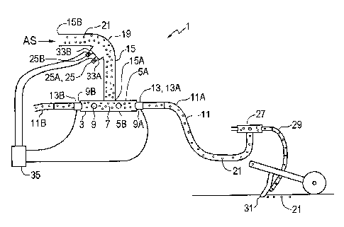
Figs. I and 2 schematically illustrate an embodiment of an air distribution
apparatus 1 of
the present invention. The apparatus I is shown as part of an air seeder
product
distribution network. The apparatus I comprises a manifold body 3 comprising
substantially circular top and bottom plates 5, as illustrated in Fig. 6,
oriented
substantially horizontally, and a substantially vertical body wall 7 extending
between the
top and bottom plates 5A, 5B. Ports 9 are defined through the body wall 7, and
a
delivery conduit I I is connected to each port 9.
A port valve 13 is configured such that when the port valve 13 is open, as
illustrated in
Fig. 1, the delivery conduit 11 is connected to the interior of the manifold
body 3 through
the port 9, and such that when the port valve 13 is closed, as illustrated in
Fig. 2, the
delivery conduit 11 is disconnected from the interior of the manifold body 3.
A substantially vertically oriented supply conduit 15 is connected at an
output end 15A
thereof to the interior of the manifold body 3 through an aperture 17 in the
top plate 5A.
The supply conduit 15 extends substantially vertically up from the manifold
body 3 to a
curved elbow 19 and then extends substantially horizontally from the elbow 19
to an
input end 15B thereof that is connected to receive a product air stream AS
with
agricultural products 21 entrained therein. The product air stream AS is
provided by a
conventional air seeder fan and metering system.
CA 02741267 2011-05-27
An exhaust orifice 33 is defined in the elbow 19 at an inner radius of the
elbow 19. An
exhaust valve 25 is configured such that when the exhaust valve 25 is open, as
schematically illustrated in Fig. 2, a selected flow of pressurized air PA
flows from an
interior of the supply conduit 15 through the exhaust orifice 33. When the
exhaust valve
25 is closed, as schematically illustrated in Fig. 1, pressurized air from the
interior of the
supply conduit 15 is prevented from flowing through the exhaust orifice 33.
The port
valve 13 and exhaust valve 25 are controlled such that when the port valve 13
closes, the
exhaust valve 25 opens.
In operation when seeding, agricultural products are carried in the air stream
AS from the
tanks carrying various seed, fertilizer, and/or mixtures of same or like
products. The air
stream AS and entrained products enter the manifold body 3 which is designed
so that
substantially equal portions of the air stream AS and agricultural products
exit through
each port 9 into the delivery conduits l 1 and, in the illustrated apparatus,
to a secondary
manifold 27 which again divides the air stream AS and entrained agricultural
products
substantially equally to each secondary delivery conduit 29 and then to the fu
row
openers 31.
When it is desired to turn off the flow of agricultural products 21 to the
secondary
manifold 27, the port valve 13 is closed, and one of the exhaust valves 25 is
opened by a
controller 35. The closing of the port valve 13 will typically be triggered by
an operator
who has visually determined that the furrow openers 31 fed by the secondary
manifold 27
are passing through previously seeded soil, or by a global positioning system
GPS which
has determined the same thing. The air flow in the delivery conduit 11 and
downstream
from there stops when the port valve 13 closes, and at the same time the
exhaust valve 25
opens.
11
.. ...............
CA 02741267 2011-05-27
The size of the exhaust orifice 33 is typically configured such that the
selected flow of
pressurized air PA flowing through the exhaust orifice 33 when the exhaust
valve 25 is
open is substantially the same as an amount of air flowing through the port 9
when the
port valve 13 is open. Thus the volume of air flow through the supply conduit
15
upstream from the elbow 19 is maintained at about the same amount whether the
port
valve 13 is open or closed, and critical velocity of the product air stream AS
will be
maintained to prevent agricultural products from falling out of the air
stream.
In the illustrated apparatus 1, the exhaust orifices 33 are defined in the
wall of the elbow
19 that forms the inner radius of the elbow 19. It has been found that a clean
air stream,
with substantially no agricultural products entrained therein, can be drawn
off the product
carrying air stream AS at the inner radius since the agricultural products 21
follow the
outer radius of the elbow 19 when making the turn from the horizontal to the
vertical
direction. Thus the selected flow of pressurized air PA can be drawn out of
the supply
conduit without losing any product 21.
In the illustrated apparatus 1 as well, the supply conduit 15 extends
vertically down from
the elbow 19 to the manifold body 3. It can be seen that as pressurized air is
drawn off at
the elbow 19 through one or more of the exhaust orifices 33, less air is
moving through
the vertical portion of the supply conduit 15. With the product air stream AS
moving
downward, the reduced volume of air in the air stream AS does not adversely
affect the
movement of the entrained product to the manifold 3 as same is drawn down by
gravity.
The apparatus I comprises first and second ports 9A, 9B, first and second
delivery
conduits 11A, 1113, and first and second port valves 13A, 13B connecting the
corresponding first and second delivery conduits I1A, 11B to the first and
second ports
9A, 9B. First and second exhaust orifices 33A, 33B are defined in the inner
radius of the
elbow 19, and corresponding first and second exhaust valves 25A, 25B for
stopping and
12
CA 02741267 2011-05-27
starting the flow of pressurized air flows from the interior of the supply
conduit 15
through the corresponding first and second exhaust orifices 33A, 33B.
The first port valve 13A and first exhaust valve 25A can be controlled such
that when the
first port valve 13A closes, the first exhaust valve 25A opens, and in the
same manner
when the second port valve 13B closes, the second exhaust valve 25B opens. The
selected flow of pressurized air PA flowing through the exhaust orifices 33A,
33B when
the first and second exhaust valves 25A, 25B are open is substantially the
same as an
amount of air flowing through the first and second ports 9A, 9B when the
corresponding
first and second port valves 13A, 13B are open.
Where, as is typical, a manifold includes six to eight ports, an exhaust
orifice and valve
can be provided for each port.
Alternatively a single adjustable exhaust valve 25' can be provided as
schematically
illustrated in Fig. 3. In a system with the exhaust valve 25', the first and
second port
valves 13A, 13B and the exhaust valve 25' are controlled such that when the
first or the
second port valve closes, the exhaust valve 25' opens to a first degree,
illustrated by the
dotted line Dl such that a first selected flow of pressurized air,
substantially equal to the
amount of air flowing through one of the ports when one port valve is open,
flows from
the inner radius of the elbow 19' of the supply conduit through the exhaust
orifice 33'.
When both the first and the second port valves 13A, 13B close, the exhaust
valve 25'
opens to a second degree, illustrated by dotted line D2, such that a second
selected flow
of pressurized air flows from the supply conduit through the exhaust orifice
33' that is
substantially the same as the amount of air flowing through the first and
second ports
when the first and second port valves 13A, 13B are open. Where further ports
are
provided, further opening of the exhaust valve 25' can be provided as well.
13
CA 02741267 2011-05-27
Thus the velocity of the air stream AS in the horizontal portion of the supply
conduit is
maintained above the critical velocity. In the apparatus 1, the exhaust
orifice 33 is open
to the atmosphere, such that pressurized air PA from the interior of the
supply conduit 15
flows through the exhaust orifice 33 into the atmosphere when the exhaust
valve 25 is
open.
As illustrated in the apparatus 1' of Figs. 4 and 5, an exhaust conduit 23 can
be connected
at an input end 23A thereof to the exhaust orifice 33 and with an output end
23B thereof
connected to an exhaust destination, such that the selected flow of
pressurized air PA
flows through the exhaust conduit 23. The exhaust destination can be selected
to suit the
particular circumstances, however beneficially in the apparatus 1', the
exhaust conduit 23
is connected at the output end 23B thereof to the delivery conduit 11 in
proximity to the
port 9. Although the exhaust valve could remain on the exhaust orifice 33 at
the input
end 23A of the exhaust conduit 23, in the illustrated apparatus 1', the
exhaust valve 25' is
moved to the output end of the exhaust conduit 23 to facilitate mounting the
port valve 13
and exhaust valve 25 in a valve assembly as described further below.
Thus when the port valve 13 is closed and the exhaust valve 25' is open, as
illustrated in
Fig. 5, the delivery conduit 11 is connected to the exhaust conduit 23 and the
selected
flow of pressurized air PA flows through the exhaust conduit 23 into the
delivery conduit
11. Thus instead of the air flow in the delivery conduit 11 and downstream
from there
immediately stopping as in the prior art gated manifold ports, when the port
valve 13
closes, the exhaust valve 25 opens such that a clean air stream, the
pressurized air PA
with substantially no agricultural products entrained therein, flows from the
inner radius
of the elbow 19 into the delivery conduit 11 and downstream through the
secondary
manifold 27 and secondary delivery conduits 29.
Thus the velocity of the air stream AS through the supply conduit 15 upstream
from the
elbow 19 is maintained and as well, agricultural products remaining in the
distribution
14
CA 02741267 2011-05-27
network downstream from the blocked port are pushed out to the furrow openers
31 so
that the products do not fall and block the conduits. When the exhaust valve
25' is
closed, as illustrated in Fig. 4, the delivery conduit 11 is disconnected from
the exhaust
conduit 23 and connected to the port to receive the product air stream AS.
Fig. 7 schematically illustrates a further alternative embodiment with a
manifold body
203, ports 209, port valves 213, delivery conduits 211, and supply conduit 215
where the
exhaust conduits 223 are connected to a clean air stream CAS that is drawn off
the
distribution network at some earlier point where a clean air stream might be
available,
such as directly off the fan output prior to the meter, or from a separate
pressurized air
source altogether. When the port valve closes, the exhaust valve 225 opens and
the clean
air stream CAS flows through the delivery conduit to clear agricultural
products from any
downstream conduits, manifolds, and the like.
Fig. 8 schematically illustrates a convenient configuration comprising a valve
assembly
337 connected to the port 309 of the manifold body 303, to the delivery
conduit 311, and
to the exhaust conduit 323. The port valve 313 and the exhaust valve 325 are
incorporated in the valve assembly 337 and are provided by butterfly type
valves oriented
at 90 degrees and connected to a vertical shaft 339 that rotates at the
command of the
controller 335. The port valve 313 and exhaust valve 325 are connected such
that when
the port valve 313 closes the exhaust valve 325 opens, which is the position
shown in Fig.
8. Then when the port valve 313 opens, the exhaust valve 325 closes. A known
plunger
type valve or other such valve as is known in the art could also be used to
provide a
connected valve that operates as described.
An alternate manifold body 403 is schematically illustrated in Fig. 10. The
manifold
body 403 is a flat fan type manifold body where the supply conduit 415 directs
the
product air stream AS into a first end of the a flat manifold body 403 which
divides the
product air stream AS into channels 461with the ports 409 at the ends of the
channels 461
CA 02741267 2011-05-27
on a second opposite end of the flat manifold body 403. An exhaust conduit 423
is
connected as described above to receive a clean air stream from an exhaust
orifice at an
upstream elbow, or from another source. A port valve 413 and exhaust valve 425
control
flow of either the product air stream AS or exhaust air stream PA to the
delivery conduit
411 as described above.
Thus the present invention provides an air stream exhaust to maintain air
speed in the
supply conduit above the critical velocity. The exhausted air can also be
directed into the
delivery conduit of the closed port to clear delivery conduits and manifolds
downstream,
or a separate clean air stream can he directed into the delivery conduit.
A method is provided of controlling delivery of an agricultural product to a
selected
section of furrow openers 31 of an air seeder 51. In a typical practice of the
method the
product air stream AS is provided by a conventional air seeder fan and
metering system
mounted on an air seeder cart 55.
In the embodiment illustrated in Fig. 9, each section of furrow openers
comprises a
secondary manifold 27 connected to a plurality of furrow openers 31. The
furrow
openers 31 are spaced laterally across a frame 53 such that all the furrow
openers fed by
one secondary manifold 27 are laterally spaced from the furrow openers fed by
an
adjacent secondary manifold 27 such that the furrow openers of one section
seed a field
strip F1, while the furrow openers fed by an adjacent secondary manifold 27
seed an
adjacent field strip F2. Thus as the strip of field area narrows to a width
less than the air
seeder 51, the flow of agricultural products is directed to selected sections
of furrow
openers 31 to seed any one or all of field strips Fl, F2, F3, F4.
Alternatively each "section" of furrow openers could comprise a single furrow
opener fed
from a secondary manifold with port and exhaust valves 13, 25 controlling the
flow of the
product air stream AS to each single furrow opener.
16
CA 02741267 2011-05-27
As shown in the accompanying drawings, the method comprises for each air
seeder
section providing a delivery conduit 11 connected at an output end thereof to
deliver the
agricultural product to the section of furrow openers 31, and connected at an
input end
thereof to a port 9 defined through a wall of a manifold body 3; connecting an
output end
of a supply conduit 15 to an interior of the manifold body 3, and directing a
product air
stream AS with the agricultural product 21 entrained therein into an input end
of the
supply conduit 15 such that the agricultural product moves through the supply
conduit 15,
the manifold body 3, the ports 9, and the delivery conduits 11 to each section
of furrow
openers 31; closing a selected port 9 to stop the delivery of the agricultural
product 21 to
a selected section of furrow openers 31 and exhausting a selected flow of
pressurized air
PA from the supply conduit 15; stopping exhausting the selected flow of
pressurized air
PA from the supply conduit 15 and opening the selected port 9 to restart the
delivery of
the agricultural product to the selected section of furrow openers 31.
To avoid exhausting agricultural products entrained in the product air stream,
the air
seeder is configured such that the supply conduit 15 extends substantially
vertically up
from the manifold body 3 to a curved elbow 19 and then extends substantially
horizontally from the elbow 19, and the selected flow of pressurized air PA is
exhausted
from the supply conduit 15 through an exhaust orifice 33 defined in the elbow
19 at an
inner radius of the elbow 19.
The selected port 9 is closed by providing a port valve 13 configured such
that when the
port valve 13 is open the delivery conduit 11 is connected to an interior of
the manifold
body 3 through the port 9, and such that when the port valve 13 is closed, the
delivery
conduit 11 is disconnected from the interior of the manifold body 3.
The delivery conduits may be cleared of agricultural products by connecting
the exhaust
orifice 33 to the delivery conduit l 1 in proximity to the input end thereof
such that the
17
CA 02741267 2011-05-27
selected flow of pressurized air PA from the supply conduit 15 passes through
the
delivery conduit 11.
Figs. 11 - 13 illustrate an air distribution manifold apparatus 501 that
comprises a
manifold body 503 with output ports 509, and a valve assembly 537 connected to
each
port 509. A substantially vertically oriented supply conduit 515 is connected
at an output
end 515A thereof to the interior of the manifold body 503. The supply conduit
515
extends substantially vertically up from the manifold body 503 to a curved
elbow 519 and
then extends substantially horizontally from the elbow 519 to an input end
515B thereof
that is connected to receive a product air stream AS with agricultural
products entrained
therein.
A delivery conduit 511, and an exhaust conduit 523 are connected to each valve
body
537. Only one of each is shown to allow for better illustration. The exhaust
conduits 523
are connected to exhaust orifices 533 at the inner radius of the elbow 519,
and the
delivery conduits 511 are connected to downstream manifolds or furrow openers.
The
port valve 513 and the exhaust valve 525 are incorporated in the valve
assembly 537 and
are provided by a plunger type valve where the valve element 541 provides both
the port
valve 513 and exhaust valve 525. When the valve element 541 is in the position
shown
in Fig. 12 the port 509 is blocked by the valve element 541 and the port valve
513 is thus
closed, and the exhaust conduit 523 is connected to the delivery conduit 511
and the
exhaust valve 525 is thus open. Then when, in response to a control signal,
the valve
element 541 moves to the position shown in Fig. 13, the port 509 is connected
to the
delivery conduit 511 and the port valve 513 is thus open, while the passage
from the
exhaust conduit 523 to the delivery conduit 511 is blocked by the valve
element and the
exhaust valve 525 is thus closed..
As described above, when the port valve 513 is closed, and the exhaust valve
525 is open,
as illustrated in Fig. 12, the delivery conduit 511 is disconnected from the
interior of the
18
CA 02741267 2011-05-27
manifold body 503 and is connected to the clean air stream from the exhaust
orifice 533
at the elbow 519, such that clean air flows through the delivery conduit 511.
When the
port valve 513 is open, and the exhaust valve 525 is closed, as illustrated in
Fig. 13, the
delivery conduit 511 is connected to the interior of the manifold body 503 and
the
product bearing air stream AS flows through the delivery conduit 511, and no
air flows
through the exhaust conduit 523.
As ports are opened and closed the rate of metering agricultural products into
the product
air stream is adjusted accordingly. The present invention maintains critical
velocity of
air flow through the distribution network and can also ensure that delivery
conduits
and/or manifolds downstream from a closed port are clear.
The foregoing is considered as illustrative only of the principles of the
invention.
Further, since numerous changes and modifications will readily occur to those
skilled in
the art, it is not desired to limit the invention to the exact construction
and operation
shown and described, and accordingly, all such suitable changes or
modifications in
structure or operation which may be resorted to are intended to fall within
the scope of
the claimed invention.
19