Note: Descriptions are shown in the official language in which they were submitted.
CA 02741278 2011-04-15
WO 2010/043860 PCT/GB2009/002458
FORCEPS
Background to the invention
The present invention relates to a forceps system for the measurement of
compression and traction forces, including the measurement of compression and
traction forces exerted upon a fetal head during instrumental delivery.
Forceps are well known for grasping objects by applying pressure to the object
to
retain it within the forceps then applying force in the desired direction of
movement of the object. For example, forceps are used to grasp crucibles of
molten metal in order to remove them from a furnace and the like. Similarly,
forceps are often used during difficult births to assist with the birthing
process by
grasping the head of the baby and applying a force in the birthing direction
to assist
with the delivery of the baby through the birthing canal.
Depending on the intended use of the forceps, the forceps blades are typically
designed to correspond to the contours of the object to be grasped. For
example,
the forceps for use in assisting childbirth have blades which are contoured
appropriately to receive a baby's head therebetween during use.
Conventional obstetrical forceps work by engaging the head of the baby whilst
still
inside the body of the mother. The forceps are then used to either turn the
baby's
head to a new position to allow natural childbirth to progress more easily,
and/or to
exert tractional or rotational force on the baby's head in order to pull the
baby
through the birth canal during delivery. The amount of traction or pressure
applied
to the skull of the baby during this delivery process is extremely important -
sufficient traction or pressure needs to be applied to achieve the desired
movement
of the baby however, too much traction or pressure can result in injuries to
the
baby, including brain, scalp and/or facial injuries. The amount of force
applied is
subject to the clinical judgement of the medical expert operating the forceps
and so
CA 02741278 2011-04-15
WO 2010/043860 PCT/GB2009/002458
2
there is no reliable way to ensure that excessive force is not applied and
that the
potential complications for the baby are avoided.
An alternative device which may be used to assist childbirth is the vacuum
extractor. With vacuum extrusion there is means available to measure the
operational forces used and exerted during the birthing process. These forces
are
then applied within `safe operating parameters' as a way of preventing
excessive
force application to the head of the baby during childbirth. However, vacuum
extrusion carries its own risks and complications, including but not limited
to
haematoma (a blood collection in the scalp). Although this type of injury is
typically resolved without further problems, occasionally life threatening
injuries
such as subgaleal (subaponeurotic) hematoma, retinal haemorrhages or
intracranial
haemorrhage may occur.
There is therefore a need for a device which is simple for a medical expert to
use,
but which allows the accurate measurement of the forces applied by the medical
expert to the baby's head during the birthing process in real time so that the
medical expert can avoid inflicting injuries on the baby during the assisted
delivery.
Summary of the Invention
The present invention seeks to address the problems of the prior art.
Accordingly, a first aspect of the present invention provides a forceps system
comprising a pair of forceps members; and force measurement means operable to
measure compressive and traction forces exerted by the forceps when in use,
and to
output measurement signals indicative of such forces.
By measuring both the compressive and traction forces in real time, it is
possible
for the operator of the forceps system to know at all times the forces being
applied
CA 02741278 2011-04-15
WO 2010/043860 PCT/GB2009/002458
3
and to adjust the applied forces to avoid the forces being applied from
becoming
excessive and resulting in damage to the object being held by the forceps
system.
This invention is particularly, although not exclusively, intended for use
during the
forceps-assisted childbirth. Thus, being able to monitor the forces being
applied to
the head of the baby in real time during this process assists in prevention of
potential injury to the head and neck of the baby during delivery.
In one embodiment, the forceps members are pivotally engaged with one another.
However, it will be appreciated that any other suitable inter-relationship
between
the forceps members allowing the desired relative movement may be used as an
alternative such as, but not limited to, hinged engagement, sliding engagement
or
rotational engagement.
In a further embodiment, at least one of the forceps members is provided with
a
pressure sensor operable to measure compressive forces.
Preferably, the pressure sensor is located on a surface of the forceps member
opposing the other forceps member. This way, the pressure sensors are located
in
such a manner so as to detect and measure the force applied by each forceps
member at the object being gripped therebetween, for example, the head of the
baby during delivery.
The pressure sensor may be selected from the group comprising
microelectromechanical (MEM) piezoresistive force sensors, quantum tunnelling
composite (QTC) sensors and force sensing resistors (FSRs).
The or each forceps member may comprise a blade portion and a handle portion
with a deformable O-ring located between the blade portion and the handle
portion.
CA 02741278 2011-04-15
WO 2010/043860 PCT/GB2009/002458
4
Thus, any deflection of the blade portion relative to the handle portion will
result in
deformation of the deformable O-ring.
Preferably, the forceps blade portions are mirror images of one another. As
the
contours of each forceps member mirror one another, this allows equal force to
be
applied through each forceps member to the object gripped there between.
Preferably, the O-ring is located adjacent the point of pivotal engagement of
the
two forceps members and may be further provided with a strain gauge mounted on
the deformable O-ring. In this way, any deformation of the O-ring will be
detected
by the strain gauge and thus the traction forces through the forceps system
may be
detected and measured. More preferably, the O-ring is located between the
point of
pivotal engagement and the forceps blade portions.
It is to be appreciated that although an embodiment of the present invention
utilises
a deformable O-ring in the measurement of traction forces through the forceps
system, any other suitable means of measuring such traction forces may be
employed in addition to or as an alternative to the deformable O-ring feature.
In a further embodiment, an array of strain gauges is mounted adjacent the
point of
pivotal engagement of the forceps members. By using an array of strain gauges,
a
more accurate measure of the traction forces through the forceps system may be
made.
Preferably, one or more of the strain gauges may be mounted on an external
cylindrical surface of the deformable O-ring. In this way, the or each strain
gauge
will be located at a region of the deformable O-ring that will experience the
most
deformation during the application of traction forces through the forceps
system
and thus the or each strain gauge will be located in a position that allows
the most
sensitive detection of force-induced deformation of the deformable O-ring.
CA 02741278 2011-04-15
WO 2010/043860 PCT/GB2009/002458
In a further embodiment, the forceps members are held together by magnetic
forces
at the point of pivotal engagement between the pair of forceps members. This
is
achieved by the provision of opposing magnets of opposite polarity, one
located on
each forceps member at the point of pivotal engagement. The provision of
5 magnetic inter-engagement facilitates smooth pivotable relative movement
between
the forceps members. Furthermore, the use of the magnetic inter-engagement
allows simple disengagement of the forceps members from one another when not
in use to facilitate cleaning and/or sterilisation of the forceps members. The
simple
separation of the forceps members means that the conventional problem of
cleaning
the forceps system at hinge points is avoided. A further advantage of the use
of
magnets is that the relative movement of forceps members is possible without
any
deformation of the deformable O-ring. Thus, any detected deformation of the
deformable O-ring is as a result of traction forces through the forceps system
and/or compressive forces through respective forceps handle portions.
A further advantage of the use of magnetic inter-engagement in a forceps
system
for use in forceps-assisted childbirth is that it assists with the reliable
inter-
engagement of the forceps members with one another during the engagement
process.
Preferably, the region of pivotal engagement of each forceps member is
provided
with contours to assist the separation of the forceps members from one another
during use. The contours preferably comprise a ramped region whereby rotation
of
the forceps members relative to one another causes each forceps member to rise
up
the ramp of the opposing forceps member, thereby separating the forceps
members
from one another at the point of pivotal engagement. This assists in
overcoming
the opposing magnetic forces and facilitating ease of separation of the
forceps
members from one another.
CA 02741278 2011-04-15
WO 2010/043860 PCT/GB2009/002458
6
Preferably, at least a portion of the forceps members comprise a resilient
material.
The resilient material may be an elastomeric polymer material, such as a
biocompatible elastomeric material, although it will be appreciated that any
other
suitable resilient material may be used in combination with, or as an
alternative to,
the elastomeric polymer material.
A further aspect of the present invention comprises a method of measuring the
compressive and traction forces exerted by a forceps system when in use, the
method comprising the steps of:
a. Providing a forceps system having a pair of forceps and force
measurement means operable to measure compressive and traction
forces exerted by the forceps;
b. Locating the forceps around an object and applying compression
and/or traction forces to the object via the forceps;
c. Transmitting the compressive and traction force measurements to a
controller;
d. Outputting said measurements to a user in real time during use of
the forceps.
The compression and/or traction forces applied at step b above may be in
addition
to additional forces applied to the object where the object is a foetal head
and the
forceps system is being used during forceps-assisted delivery.
The outputting of the measured force data may involve the transmission of the
data,
either by wireless technology (including but not restricted to Bluetooth
technology,
radio frequencies and infra red technology) or by cable transmission, to a
controller
such as a computer or the like. The received force data may be visualised by
means of a viewer or display unit such as but not restricted to a computer
screen or
the like. In addition, the controller may be provided with alarm means, such
as an
CA 02741278 2011-04-15
WO 2010/043860 PCT/GB2009/002458
7
audible and/ or visual alarm signal or the like, to indicate when the received
force
measurements fall outside of a predetermined range.
The controller may record the received force data over time during the
procedure of
use such that a record of the procedure is available for reference after the
event is
complete. The recorded force data may optionally be archived, analysed and
subsequently used to develop and implement pre-emptive warning systems for use
during future forceps system operations.
Brief Description of the Drawings
Embodiments of the present invention will now be described, by way of example
only, and with reference to the accompanying drawings, in which:
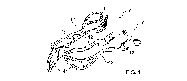
Figure 1 is a perspective view of an embodiment of two forceps systems;
one in an engaged configuration and one in an unengaged configuration; .
Figure 2 is a perspective view of an embodiment of the forceps system of
figure 1 together with an associated charging unit;
Figure 3 is an exploded view of a forceps member of the forceps system of
figure 1;
Figure 4A is a view of the electronic component of a forceps system of
figure 1;
Figure 4B is a view of a further component of the forceps system of figure
1;
Figure 5 is a graphical representation of a display output based on
measurements taken by sensors at various positions around the forceps blade of
a
forceps member of the forceps system of figure 1;
Figure 6 illustrates the forceps of figure 1 in use in an obstetric situation;
Figure 7 is a perspective view of the forceps system of figure 1 illustrating
the range of movement possible using magnetic forces to engage the pair of
forceps
members with one another in use;
CA 02741278 2011-04-15
WO 2010/043860 PCT/GB2009/002458
8
Figure 8 is a further view of the forceps system of figure 1 in the fully
closed position; and
Figure 9 is a partial perspective view of the embodiment of figure 1
showing the locations of the inter-engagement region at one of the pair of
forceps
members.
Detailed Description of the Invention
Figure 1 shows an embodiment of a forceps system 10 according to a first
aspect of
the present invention with the forceps members 12, 12' in an assembled state
and
also a further two forceps members 12, 12' in the unassembled state. Figures
4A
and 4B show components of forceps member 12. The forceps system 10 of figure
1 is intended for obstetric use during forceps delivery.
Each of forceps members 12, 12' comprises a blade portion 14 at a first end
thereof
and a respective handle portion 16 at an opposing end thereof, with a
respective
deformable element in the form of a deformable O-ring 20. The deformable O-
ring
is composed of a resilient material which deforms under applied force exerted
through the forceps system 10.
20 It will be appreciated that blade portion 14 of forceps member 12 is a
mirror image
of blade portion 14 of forceps member 12'. The opposing surfaces of respective
forceps blade portions 14, which contact and grip the object to be held
therebetween, are composed at least in part of an elastomeric polymer which
provides a resilient contact surface for gripping the head of a baby during
the
birthing process. However, it will be appreciated that any suitably resilient
material may be used in addition to, or as an alternative to, such an
elastomeric
material.
Deformable O-ring 20 is annular and an array of strain gauges 21 is provided
on
the external cylindrical surface of the deformable O-ring 20. Each strain
gauge 21
CA 02741278 2011-04-15
WO 2010/043860 PCT/GB2009/002458
9
within the array is position to detect deformation of the adjacent O-ring
region
when traction force is applied through the forceps system 10. Thus, the
provision
of such an array of strain gauges 21 on the outer cylindrical surface of the
deformable O-ring 20 allows for traction force identification and measurement
on a
plurality of planes.
In addition, the array of strain gauges 21 is also able to identify and
measure
compressive force applied across the handle portion 16 due to the resultant
deformation of the deformable O-ring on application of such compressive force
to
bring the blade portions 14 of respective forceps members 12, 12' towards one
another, in use.
When the forceps system 10 is assembled the two forceps members 12, 12' are
position such that respective blade portions 14 of forceps members 12 and 12'
are
facing one another and the two forceps members 12, 12' are pivotally engaged
with
one another at pivot point 18, such that respective deformable O-rings become
aligned.
Each of forceps members 12 and 12' are provided with a magnet 24, each magnet
being of opposite polarity such that respective magnets 24 are attracted to
one
another. In use, forceps members 12, 12' are held in engagement at pivot point
18
under the magnet attractive forces of opposing magnets 24.
Thus, in use, forceps members 12, 12' are pivotable relative to one another
about
pivot point 18 but are held together at pivot point 18 under magnetic forces.
Figure
7 shows the two forceps members 12, 12' being brought together such that the
magnets 24 are brought into contact with one another. The forceps members 12,
12' are brought together in the direction of the arrows shown in figure 7.
Disengagement of this pivot is through mechanical means and contrary to the
CA 02741278 2011-04-15
WO 2010/043860 PCT/GB2009/002458
magnetic engagement forces - ensuring definite and/or intended engagement and
disengagement of the forcep members.
Figure 3 shows an exploded view of forceps member 12 with each of the
5 component parts indicated. As can be seen, blade portion 14 is composed of
an
outer blade portion 26 and inner blade portion 28. The inner and outer blade
portions 26, 28 are metal substructure with a plastic over-moulding. When
located
in position relative to one another they create a hollow structure within
which is
housed the internal electronics, including sensors 34.
Inner and outer blade portions 26, 28 are ultrasonically welded together to
create
two separate forceps members 12, 12' which are mirror images of one another
with
the internal electronics (including sensors 34) securely located therebetween.
Sensors 34 are MEM sensors and are positioned to detect compression forces
exerted by the forceps blades on an object being gripped, during use. The
forceps
system shown in the figures is intended for use in the birthing process to
facilitate a
forceps delivery. Therefore, the forceps blade portions 14 are contoured to
correspond to the contours of a baby's skull. The sensors 34 are therefore
positioned to measure the compression forces applied by the forceps blade
portions
14 to the baby's skull during the forceps delivery process.
The compression and traction forces detected and measured by sensors 34 and
the
array of strain gauges are regulated and calibrated within the handle portion
16 of
the forceps system 10 by means of a processing card (not shown) through a
series
of amplification.
However, it will be appreciated that the signal amplification, calibration and
processing
may take place by any suitable means available to the skilled person. For
example, the
signal amplification, calibration and processing may occur on a small chip
board adapted
to be received within a conventional PCMCIA card slot or the like.
Alternatively, the
amplification and/or calibration/processing may take place on a PCI card
within a PC, in a
separate processing unit or even on a single chip housed within the forceps
system itself.
CA 02741278 2011-04-15
WO 2010/043860 PCT/GB2009/002458
11
The detected force data is then wirelessly transmitted to a controller such as
a computer or
the like using Bluetooth technology. It will be appreciated that alternative
wireless
communication technologies may be applied. Alternatively, wired communication
may be
used. A wireless embodiment of a forceps system 10 in accordance with the
present
invention is shown in figure 8. However, wireless communication methods have
the
advantage that the forceps system mobility is unhampered by the presence of
the tethered
connection to the controller which processes the detected force data.
However, the detection and amplification of the forces detected through the
forceps system
10 and the onward transmission of the collected data to a controller for
outputting and/or
visualising the data for real time viewing by a user requires an energy
source.
This may be achieved in several conventional ways. For example, the embodiment
of a
forceps system 10 shown in figure 1 is rechargeable and in figure 3 is shown
being
inserted into it accompanying recharger unit 32, the forceps system 10 being
moved into position relative to the charger in the direction of the arrow
shown.
Contacts provided on the outer surface of the handle portion16 of the forceps
system make contact with contacts provided at the recharger unit 32. The
recharger unit 32 may provide power to recharge a battery within the handle
portions 16 of the forceps members 12 of forceps system 10. The recharger unit
32
may be plugged in to the mains as a source of power. Alternatively, it will be
appreciated that the recharger unit may include a battery which donates power
to
the rechargeable battery in the forceps system. The recharger unit 32 acts as
a
docking station for the forceps system 10 when not in use, thus the docked
forceps
system 10 will be in a suitable state for use when required.
Figure 6 shows the forceps system 10 in use during a forceps delivery
procedure.
The forceps system 10 is guided into position such that opposing forceps blade
portions 14 are position on opposing sides of the head of the baby. Once in
position, compressive forces are applied by a use through the handle portions
16
CA 02741278 2011-04-15
WO 2010/043860 PCT/GB2009/002458
12
thereby gripping the head of the baby between the opposing forceps blade
portions
14. In addition, during the delivery process, cervical forces may be applied
from
the mother's cervical skeleton and as a result of the muscular contractions
which
result in compressive forces being application to the forceps system. These
forces
are independent of the forces applied by a user to the forceps system during
use.
However, these cervical forces will also be included within the measured
forces
detected by the forceps system during use due to their compressive effect on
the
deformable O-ring 20 and the compressive force on the MEM's sensors (or
other).
It is the collective value which is of primary importance with this system.
The compressive forces are detected by the sensors 34 located at the forceps
blade
portions 14, the measured force data being amplified then wirelessly
transmitted to
the controller where the data is visualised in real time for viewing by a
user. In this
way, the user may be aware at all times of the compressive forces being
applied to
the head of the baby and can therefore avoid the application of excessive
force that
may result in injury to the baby's skull.
Once the baby's head is gripped between the blade portions 14 of the forceps
system 10, the user applies traction force to the head of the user (in tandem
with
the natural contraction forces of the mother) in the direction of delivery.
Any
resistance to being pulled in the direction of delivery results in traction
forces being
applied through the forceps system 10 causing deformation of the deformable 0-
ring 20. The traction forces are detected and measured by the array of strain
gauges positioned at the deformable 0-ring 20, amplified, and then transmitted
wirelessly to the controller where the data is visualised in real time for
viewing by
the user. In this way, the user may be aware at all times of the traction
forces being
applied through the forceps system 10 and can therefore avoid the application
of
excessive force that could cause injury to the baby's skull. The inverse of
this is
also possible whereby a negative reading is generated when a pushing force is
applied upon the fetal head. This is of even greater danger than the primary
force or
CA 02741278 2011-04-15
WO 2010/043860 PCT/GB2009/002458
13
compressive/ traction force. The system also accommodates measurement and
warnings of this.
Thus, by detecting forces using both sensors 34 and the array of strain
gauges, the
forceps system 10 of the present invention measures both the traction (and
potential
pushing) force exerted by the user and the compressive forces exerted by the
combined traction force of the user, the contraction force of the mother and
the
natural resistance formed by the shape of the pelvis during the delivery
procedure.
The forceps system 10 may be provided with a movement switch (not shown)
which may be embedded in the handle portion 16 of one or each forceps member
12, 12' such that movement of the forceps system 10 activates force detection
view
the sensors 34 and strain gauge array 22. Alternatively, the forceps may
switch on
automatically if mains powered simply by being plugged into the mains. Where a
wireless version is used, a warning indicator, such as an LED display or the
like,
may be provided to indicate when battery power reaches a predetermined
threshold
level.
Finally, the handle portion 16 may be tailored ergonomically to suit the
requirements of a user by the selective use of a two-shot injection moulding
technique to provide ergonomic grip areas within the contours of the handle
portion
16 thereby increasing the comfort for the user and ultimately the ease of use
of the
forceps system 10 in practice.
Although aspects of the invention have been described with reference to the
embodiment shown in the accompanying drawings, it is to be understood that the
invention is not limited to the precise embodiment shown and that various
changes
and modifications may be effected without further inventive skill and effort.
For
example, it will be appreciated that although the exemplified forceps system
is
intended for forceps delivery during the birthing process, a forceps system in
CA 02741278 2011-04-15
WO 2010/043860 PCT/GB2009/002458
14
accordance with the present invention may be used for many other purposes
beyond human obstetrics and gynaecology, including but not restricted to
veterinary, medical, and surgical applications, and is not restricted to use
during the
delivery process. If desired, the contours of the blade portions may be
modified to
correspond to the object to be gripped therebetween such that the pressure
sensors
are located adjacent points of contact of the blade portions with the object
to be
gripped therebetween.