Language selection

Search

Patent 2741452 Summary

Third-party information liability

Some of the information on this Web page has been provided by external sources. The Government of Canada is not responsible for the accuracy, reliability or currency of the information supplied by external sources. Users wishing to rely upon this information should consult directly with the source of the information. Content provided by external sources is not subject to official languages, privacy and accessibility requirements.

Claims and Abstract availability

Any discrepancies in the text and image of the Claims and Abstract are due to differing posting times. Text of the Claims and Abstract are posted:

  • At the time the application is open to public inspection;
  • At the time of issue of the patent (grant).
(12) Patent: (11) CA 2741452
(54) English Title: SURGICAL LASER TIP APPARATUS WITH ALIGNMENT ASSEMBLY
(54) French Title: DISPOSITIF CHIRURGICAL A POINTE LASER AVEC ENSEMBLE D'ALIGNEMENT
Status: Deemed expired
Bibliographic Data
(51) International Patent Classification (IPC):
  • A61B 18/22 (2006.01)
(72) Inventors :
  • DI SESSEA, ALEXANDRE B. (United States of America)
  • BOITER, MIHAI (United States of America)
(73) Owners :
  • DEN-MAT HOLDINGS, LLC (United States of America)
(71) Applicants :
  • DISCUS DENTAL, LLC (United States of America)
(74) Agent: NELLIGAN O'BRIEN PAYNE LLP
(74) Associate agent:
(45) Issued: 2016-03-22
(86) PCT Filing Date: 2009-10-08
(87) Open to Public Inspection: 2010-04-29
Examination requested: 2011-10-11
Availability of licence: N/A
(25) Language of filing: English

Patent Cooperation Treaty (PCT): Yes
(86) PCT Filing Number: PCT/US2009/060014
(87) International Publication Number: WO2010/047967
(85) National Entry: 2011-04-21

(30) Application Priority Data:
Application No. Country/Territory Date
12/257,665 United States of America 2008-10-24

Abstracts

English Abstract


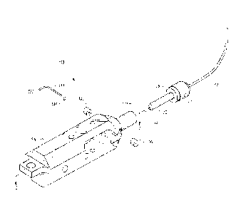
An assembly for alignment of a sterile, releasably locking optical tip
assembly housing an optical fiber connection
to a laser surgical device includes a conductive wire sensing element. A
second embodiment includes an emitter and a detector.


French Abstract

L'invention concerne un ensemble pour aligner un ensemble de pointe optique stérile à verrouillage détachable contenant une connexion à fibre optique avec un dispositif chirurgical à laser, comprenant un élément de détection de fil conducteur. Un deuxième mode de réalisation concerne un émetteur et un détecteur.

Claims

Note: Claims are shown in the official language in which they were submitted.


5
CLAIMS
We claim:
1. A tip apparatus for a reusable laser surgical device, the tip apparatus
comprising:
a) a disposable tip housing with a first end having a longitudinal axis and
adapted to
releasably fit on the distal end of the surgical device;
b) an optical fiber for delivery of light energy axially positioned within
the tip
housing from within the first end and extending beyond the tip housing;
c) means for releasably locking the tip housing first end to the surgical
device; and
d) a laser housing assembly that receives the first end of the tip housing,
wherein the
laser housing assembly includes a channel that is sized to receive the tip
housing first end
along the longitudinal axis, and a conductive wire sensor having two ends
positioned
transverse to the tip housing longitudinal axis, whereby the conductive wire
sensor contacts
the tip housing first end when ti is properly positioned within the channel,
and wherein
contact between the conductive wire sensor and the tip housing first end
closes an
electrical circuit.
2. The tip apparatus of claim 1, wherein the conductive wire sensor is
housed within
the laser housing assembly by insulated tubing.
3. The tip apparatus of claim 1, wherein the wire sensor comprises gold
plated
steel.
4. The tip apparatus of claim 1, wherein the laser housing assembly incudes
an emitter
element and a detector element positioned on either side of the channel,
whereby the
emitter and detector elements can detect whether the tip housing first end is
positioned in
the channel.

6
5. The tip apparatus of claim 1, wherein means for releasably locking the
first end to
the surgical device comprises at least one member of the group consisting of
means for
magnetic coupling, means for mechanical coupling, means for electro-mechanical

coupling, and means for electro-magnetic coupling.
6. The tip apparatus of claim 1, wherein the tip housing is made of at
least one
member of the group consisting of polyimide, polycarbon, stainless steel,
steel, iron,
plastic, and aluminum.
7. The tip apparatus of claim 1 packaged as a sterile assembly.

Description

Note: Descriptions are shown in the official language in which they were submitted.


CA 02741452 2011-04-21
WO 2010/047967
PCT/US2009/060014
1
SURGICAL LASER TIP APPARATUS WITH
ALIGNMENT ASSEMBLY
BACKGROUND OF THE INVENTION
This invention relates to surgical instruments for laser ablation procedures.
More
particularly, the invention relates to a tip apparatus having an assembly for
proper
optical fiber alignment with a laser diode for such surgical instruments.
BRIEF SUMMARY OF THE INVENTION
In practice, medical laser treatment using hand-held instruments has generally
been
developed for ophthalmic, dental, orthopedic, and similar surgical procedures
where the
treatment area is confined or particularly difficult to reach. Typically,
laser light is
transmitted from a laser source though an optical fiber to a treatment site.
The optical
fiber terminates proximally in a laser source connector for connection to the
laser
source and terminates distally in a handpiece manipulated by the surgeon.
With known systems, a handpiece used during one procedure often cannot be used
with another patient in a subsequent procedure unless some form of
sterilization is
performed. Types of sterilization techniques range from autoclaves to gas. Gas
procedures are time consuming and costly. Autoclave temperatures generally
have
proven too severe for laser surgical handpieces to withstand. These problems
could be
overcome using a sterile, disposable tip for use with a laser surgical device.
Use of
disposable tips, however, present optical alignment problems between the tips
and the
diode laser source in the surgical instrument.
Accordingly it would be useful to provide a sterile, disposable tip having a
quick and
easy to use alignment and connection assembly for use with a laser surgical
device,
such as our disposable surgical tip apparatus disclosed and claimed in pending
U.S.
Non-provisional Patent Application Serial No. 12/115,336, filed on May 5,2008
["the

CA 02741452 2015-03-12
Application No. 2,741,452
Attorney Docket No. 33226-32
2
'336 Application"].
It would be of further use if the sterile, disposable tip provided means for
precise
alignment of the optical fiber in the tip to the source of laser energy in the
surgical
device.
Yet another useful advantage would be for the sterile, disposable tip to be
releasably attached to the device with precise optical, mechanical, magnetic,
electro-
mechanical, or electro-magnetic locking and alignment assembly.
For a more complete understanding of the above and other features, advantages,

and objects of the invention, reference should be made to the following
detailed
description of a preferred embodiment, and to the accompanying drawings.
BRIEF DESCRIPTION OF DRAWINGS
Fig. us an exploded perspective view of an embodiment of disposable tip
apparatus 100 with alignment assembly adapted to a reusable surgical device
laser
housing 500.
Fig. 2 is a cut away perspective view of a first embodiment of an assembled
reusable surgical device laser housing 500 of Fig. 1 taken at "2 - 2" with the
disposable
tip apparatus 100 adapted thereto.
Fig, 3 is a cut away perspective view of a second embodiment of an assembled
reusable surgical device laser housing 500 with the disposable tip apparatus
100A with
alignment assembly adapted thereto.
DETAILED DESCRIPTION OF THE INVENTION
With reference to drawing Figs. 1 - 3, disposable tip apparatus 100 and 100A
for
optical alignment with reusable laser surgical device are presented. The
reference
numerals 100 and 100A designate generally typical apparatus for optical
alignment of a
disposable tip with a reusable laser surgical device.
Our disposable surgical tip apparatus is disclosed in the '336 Application.
An embodiment for apparatus 100 for optical alignment of a disposable tip with
a
reusable laser surgical device, includes the following combined elements: a
disposable

CA 02741452 2011-04-21
WO 2010/047967
PCT/US2009/060014
3
tip housing 10 with a first end 12 having a longitudinal axis 14 and adapted
to releasably
fit on the distal end 510 of the surgical device laser housing 500; optical
fiber means 30
for delivery of light energy axially positioned within the tip housing 10 from
within the
first end 14 and extending beyond the housing 10; assembly 16 for releasably
locking
the tip housing first end 14 to the surgical device laser housing assembly
500; and
assembly for aligning optical fiber means 30 within the tip housing 10 to a
source of
laser light energy, such as a diode laser, within the surgical device laser
housing
assembly 500 for surgical laser treatment.
The tip apparatus 100 provides a channel 520 within the surgical device laser
housing assembly 500 sized to receive the tip housing first end 12 along the
longitudinal
axis 14 for aligning the optical fiber means 30 within the tip housing 10 to
the surgical
device laser housing assembly 500. The surgical device laser housing assembly
500 is
adaptably sized and configured to direct diode laser light energy from within
the laser
housing assembly 500 to the optical fiber means 30 within the tip housing 10
once the
tip housing first end 12 is fully positioned within the surgical device
channel 520.
An embodiment of the tip apparatus 100 provides a conductive wire sensor 530
made from gold plated steel and having two ends, 532 and 534, within the
surgical
device laser housing assembly 500 positioned transverse to the tip housing
longitudinal
axis 14, whereby the conductive wire sensor 530 contacts the tip housing first
end 12
when it is fully positioned within the surgical device channel 520. Contact
between the
conductive wire sensor 530 and tip housing first end 12 causes the conductive
wire
sensor 630 to close an electrical circuit (not shown) within the surgical
device laser
housing assembly 500 and allows use of the tip apparatus 100, Figs. 1 and 2.
The conductive wire sensor 530 is housed within the surgical device housing
assembly 500 by insulated tubing 540.
An embodiment of the apparatus 100 provides an assembly 16 for releasably
locking the first end 12 to the laser housing channel 520 comprising at least
one
member of the group consisting of means for magnetic coupling, means for
mechanical
coupling, means for electro-mechanical coupling, and means for electro-
magnetic

CA 02741452 2011-04-21
WO 2010/047967
PCT/US2009/060014
4
coupling.
A second embodiment 100A includes an emitter element 50 and a detector
element 52 providing an optical sensing assembly, Fig. 3, to indicate when the
tip
housing first end 12 is fully positioned within the surgical device channel
520 and
properly aligned with the laser housing assembly 500. When the tip housing
first end
12 is properly positioned within the surgical device channel 520 and properly
aligned
with the laser housing assembly 500, the optical sensing assembly closes an
electrical
circuit (not shown) within the surgical device laser housing assembly 500 and
allows
use of the tip apparatus 100A.
An embodiment of the tip housing 10 is made of at least one member of the
group
consisting of polyimide, polycarbon, stainless steel, steel, iron, plastic,
and aluminum.
An embodiment of the tip apparatus 100 is packaged as a sterile assembly.
It should be understood, of course, that the specific forms of the invention
illustrated
herein and described are intended to be representative only, as certain
changes may be
made therein without departing from the clear teachings of the disclosure.
Accordingly,
reference should be made to the following appended claims in determining the
full
scope of the invention.

Representative Drawing
A single figure which represents the drawing illustrating the invention.
Administrative Status

For a clearer understanding of the status of the application/patent presented on this page, the site Disclaimer , as well as the definitions for Patent , Administrative Status , Maintenance Fee  and Payment History  should be consulted.

Administrative Status

Title Date
Forecasted Issue Date 2016-03-22
(86) PCT Filing Date 2009-10-08
(87) PCT Publication Date 2010-04-29
(85) National Entry 2011-04-21
Examination Requested 2011-10-11
(45) Issued 2016-03-22
Deemed Expired 2018-10-09

Abandonment History

There is no abandonment history.

Payment History

Fee Type Anniversary Year Due Date Amount Paid Paid Date
Registration of a document - section 124 $100.00 2011-04-21
Application Fee $400.00 2011-04-21
Request for Examination $800.00 2011-10-11
Maintenance Fee - Application - New Act 2 2011-10-11 $100.00 2011-10-11
Registration of a document - section 124 $100.00 2012-08-15
Maintenance Fee - Application - New Act 3 2012-10-09 $100.00 2012-10-02
Maintenance Fee - Application - New Act 4 2013-10-08 $100.00 2013-10-07
Registration of a document - section 124 $100.00 2014-02-21
Maintenance Fee - Application - New Act 5 2014-10-08 $200.00 2014-09-25
Maintenance Fee - Application - New Act 6 2015-10-08 $200.00 2015-10-02
Final Fee $300.00 2016-01-12
Maintenance Fee - Patent - New Act 7 2016-10-11 $200.00 2016-09-06
Owners on Record

Note: Records showing the ownership history in alphabetical order.

Current Owners on Record
DEN-MAT HOLDINGS, LLC
Past Owners on Record
DISCUS DENTAL, LLC
ZILA, INC.
Past Owners that do not appear in the "Owners on Record" listing will appear in other documentation within the application.
Documents

To view selected files, please enter reCAPTCHA code :


To view images, click a link in the Document Description column. To download the documents, select one or more checkboxes in the first column and then click the "Download Selected in PDF format (Zip Archive)" or the "Download Selected as Single PDF" button.

List of published and non-published patent-specific documents on the CPD .

If you have any difficulty accessing content, you can call the Client Service Centre at 1-866-997-1936 or send them an e-mail at CIPO Client Service Centre.


Document
Description 
Date
(yyyy-mm-dd) 
Number of pages   Size of Image (KB) 
Representative Drawing 2011-06-23 1 12
Cover Page 2011-06-23 1 37
Abstract 2011-04-21 1 60
Claims 2011-04-21 3 119
Drawings 2011-04-21 2 50
Description 2011-04-21 4 176
Representative Drawing 2016-02-11 1 9
Cover Page 2016-02-11 1 35
Description 2014-06-04 4 179
Claims 2014-06-04 2 55
Description 2015-03-12 4 176
PCT 2011-04-21 8 403
Assignment 2011-04-21 12 361
Prosecution-Amendment 2011-10-11 1 50
Assignment 2012-08-15 21 1,038
Correspondence 2012-08-15 2 72
Prosecution-Amendment 2013-12-16 2 74
Assignment 2014-02-21 10 334
Prosecution-Amendment 2015-02-25 3 190
Prosecution-Amendment 2014-06-04 6 228
Prosecution-Amendment 2015-03-12 3 106
Final Fee 2016-01-12 1 42