Note: Descriptions are shown in the official language in which they were submitted.
CA 02741506 2011-04-21
WO 2010/053768 PCT/US2009/062309
LOW MOUNT THREE POINT ENGINE AND PUMP MOUNTING
BACKGROUND
[0001] The present discussion is related to power machines, such
as a wheeled loader having an engine-powered drive system. The
present discussion is more particularly related to systems and
methods for mounting the engine-powered drive system to a frame
of the loader.
[0002] Power machines such as skid steer loaders, tracked
vehicles, mini-excavators, utility vehicles, wheel loaders and
the like have high utility in construction, landscaping,
agriculture, and many other types of applications. Power
machines of this type have engines that supply power to drive
systems, which transmit the supplied power to a form that can be
used to cause the power machine to move. Power systems such as
engines and drive systems are necessarily attached to the frame
of the machine. Such systems are known to vibrate due to the
activity required to generate the necessary power. It is
advantageous to attach the engine and drive systems to the frame
in such a way as to minimize the transfer of vibration between
the frame and the engine and drive systems.
SUMMARY
[0003] In one aspect, a loader is discussed. The loader has a
frame with a proximal end, a distal end, and first and second
opposing sides, an engine, and a drive system operably coupled
to the engine for causing the loader to move relative to a
support surface. The drive system includes an arrangement of
one or more hydraulic pumps attached to the engine to form, with
the engine, a power system. The power system is positioned
within the frame of the loader. The loader further includes an
1
CA 02741506 2011-04-21
WO 2010/053768 PCT/US2009/062309
attachment system to fasten the power system to the frame. The
attachment system has first and second connection points
positioned in close proximity to a center of gravity of the
power system relative to the direction between the proximal and
distal ends of the loader and a third connection point
positioned distally from the first and second connection points.
The positions of the first, second and third connection points
connect the power system to the frame to allow most of the
weight of the power system to be loaded onto the first and
second connection points.
[0004] In another aspect, an attachment system for attaching a
power system to a frame of a power machine is discussed. The
power machine has a proximal and a distal end, opposing first
and second sides, and a top and a bottom. The power system
includes an engine and one or more hydraulic pumps attached to
the engine. The center of gravity of the power system is
defined by the distribution of mass in the engine and the one or
more hydraulic pumps with respect to a proximal to distal
direction, a first to second side direction and a top to bottom
direction. The attachment system includes first, second, and
third connection points for connecting the power system to the
frame. Each of the first and second connection points are
positioned in close proximity to the center of gravity with
respect to the proximal to distal direction of the power system.
The third connection point is located away from the center of
gravity towards the distal end in the proximal to distal
direction.
[0005] In yet another aspect, a method of attaching a power
system to a frame of a loader is discussed. The method includes
positioning the power system, which includes an engine and one
2
CA 02741506 2011-04-21
WO 2010/053768 PCT/US2009/062309
or more hydraulic pumps coupled to the engine relative to the
frame so that the power system can be attached to the frame at
selected first, second, and third connection points on the power
system. The first and second connection points are positioned
in close proximity to a center of gravity of the power system as
it relates to a proximal to distal direction of the frame. The
third connection point is positioned toward a distal end of the
frame relative to the center of gravity of the power system.
The method further includes attaching the power system to the
frame at the first, second and third connection points.
BRIEF DESCRIPTION OF THE DRAWINGS
[0006] FIG. 1 is a side elevation view of a power machine of the
type in which a mounting system for an engine and related power
components discussed herein might be useful.
[0007] FIG. 2 is a block diagram that provides a schematic
illustration of a power system for the loader of FIG. 1.
[0008] FIG. 3 is a side elevation view of an outline of an
engine and hydraulic pump system illustrating connection points
for attaching the engine and hydraulic pumps to a frame of a
power machine according to one illustrative embodiment.
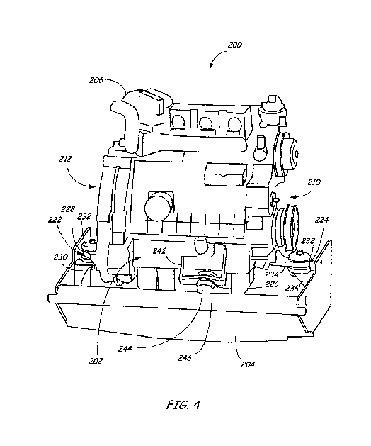
[0009] FIG. 4 is a perspective view of the outline of an engine
and hydraulic pump system taken from a distal end illustrating
connection points for attaching the engine and hydraulic pumps
to a frame of a power machine according to one illustrative
embodiment.
[0010] FIG. 5 is a flowchart illustrating a method of attaching
a power system to the frame of a loader according to one
illustrative embodiment.
3
CA 02741506 2011-04-21
WO 2010/053768 PCT/US2009/062309
[0011] While the above-identified figures set forth one or more
illustrative embodiments, other embodiments are also
contemplated, as noted herein. In all cases, concepts presented
herein describe the embodiments by way of representation and not
by limitation. It should be understood that numerous other
modifications and embodiments can be devised by those skilled in
the art which fall within the scope and spirit of the principles
of the discussion herein.
DETAILED DESCRIPTION
[0012] FIG. 1 illustrates a power machine 10 of the type in
which an engine and pump mounting arrangement of the type
discussed in the embodiments below can be usefully employed.
Power machine 10 includes a frame 12 that is supported by wheels
14. Power machine 10 has an engine (not shown in FIG. 1) that
applies power to a drive system (not shown in FIG. 1) , which in
turn supplies power to the wheels 14 causing power machine 10 to
move under the control of an operator. Examples of drive
systems for use in power machine 10 will be discussed in more
detail below. Frame 12 supports a cab 16, which defines an
operating compartment.
[0013] An operator can be located inside the cab 16 and control
the power machine 10 by manipulating control devices (not shown
in FIG. 1) located therein to send operator input signals to the
drive system. Although the power machine 10 is shown having a
plurality of wheels 14, it should be appreciated that power
machine 10 need not have wheels. As one alternative example,
power machine 10 can be equipped with one or more tracks that
are configured to engage a supporting surface, such as ground,
to propel the power machine over the supporting surface.
4
CA 02741506 2011-04-21
WO 2010/053768 PCT/US2009/062309
[0014] Power machine 10, as illustrated in FIG. 1, further
includes a lift arm 18. Lift arm 18 is coupled to frame 12 at
pivot point 26. Actuator 20 is coupled to the frame 12 at first
pivot point 22 and the lift arm at second pivot point 24.
Actuator 20, of the power machine 10 shown in FIG. 1 is a
hydraulic cylinder, although other suitable types of actuators
may be used. A single lift arm 18 is shown in FIG. 1, but it is
to be understood that a similar lift arm 18 and corresponding
actuator 20 may be positioned on the opposite side of the cab
and similarly attached to frame 12. Further, it should be
understood that such a lift arm may be coupled to the lift arm
18 shown in FIG. 1 via a cross-member (not shown) extending
between and attached to each of the lift arms 18.
[0015] Power machine 10 further includes an attachment interface
28, which is rotatably coupled to the lift arm 18 about
attachment point 30. One or more tilt actuators (not shown) are
coupled to the attachment interface 28 and the one or more lift
arms 18 (or the cross-member therebetween). Actuation of the
one or more tilt actuators causes the attachment interface 28 to
rotate about the attachment point 30 in a direction shown by
arrow 38. Attachment interface 28 is configured to engage and
be attached to a variety of different work implements such as a
bucket, a planer, a post-hole auger, and the like. By utilizing
the various attachments available to be connected to the power
machine 10 at attachment interface 28, the power machine 10
provides a desirable and suitable tool to accomplish a number of
different types of tasks. For example, by attaching a bucket
(not shown) to power machine 10, an operator is capable of
digging earth, moving material, and any number of tasks related
to landscaping, construction, material removal, or any number of
different types of applications.
CA 02741506 2011-04-21
WO 2010/053768 PCT/US2009/062309
[0016] The power machine 10 has a proximal end 40 and a distal
end 42. An accessible engine compartment is located toward the
distal end 42 of the power machine 10. The engine compartment
is accessible via an aperture normally covered by a tailgate 44.
The tailgate 44 is illustratively a latchable hinged door. The
power machine 10 has a first side 46 and an opposing second
side, not shown in FIG. 1. The power machine 10 has a top 48
and a bottom 50, which are defined for the purposes of this
discussion.
[0017] The power machine 10 illustrated in FIG. 1 is a skid
steer loader. A skid steer loader has rigid axles coupled to
each of the wheels 14. The wheels 14 on each side of the skid
steer loader are operably coupled to each so that they operate
in tandem. Each side of the skid steer loader has its own drive
system, which supplies power to the wheels on that particular
side. Steering is accomplished by controlling the drive system
of one or both sides of the machine to cause the machine to skid
on the supporting surface in a direction that is desired by the
operator.
[0018] As one illustrative example, an operator wishing to move
or turn power machine 10 to the right may cause the wheels 14 on
the left side of the power machine 10 to move in a forward
direction. In addition, the operator can cause the wheels 14 on
the right side to move in a reverse direction, not at all, or in
a forward direction at a lesser rate of speed than the left side
wheels 14. The net effect is a forward force applied to the
left side of the power machine 10 that is greater than the
forward force applied to the right hand side. As a result, the
power machine 10 will skid on its wheels 14 to the right. This
is just one non-limiting example of how a skid steer loader can
6
CA 02741506 2011-04-21
WO 2010/053768 PCT/US2009/062309
be operated. Other steering operations can be employed to
accomplish a right turn, for example. Although the illustrative
example of the power machine 10 in FIG. 1 is a skid steer
loader, the discussion provided in this document need not be
limited to skid steer loaders. Alternatively, and without
limitation, the discussion herein can be applied to other power
machines such as wheeled loaders with a front or rear steerable
axle, excavators, utility vehicles, all-wheel steer vehicles,
tracked loaders, or any other similar power machine.
[0019] FIG. 2 is a block diagram of a portion of a power system
100 for power machine 10 according to one illustrative
embodiment. Power system 100 includes an engine 102, which
generates power for various functions on power machine 10.
Power system 100 also includes a transmission package 104, which
is operably coupled to the engine 102. Transmission package 104
is powered by the engine 102 and illustratively provides power
to cause the power machine 10 to move when desired.
Transmission package 104, as is illustrated in FIG. 2 includes a
pair of hydrostatic drive pumps 106, each of which are capable
of providing power in the form of hydraulic fluid received from
a hydraulic reservoir 108 to hydraulic motors 110. Each of the
hydraulic motors 110 are, in turn, operably coupled to a pair of
axles 112 located on one side of power machine 10. Each axle
112 is coupled to a wheel 14. Hydraulic fluid provided to
either or both of the hydraulic motors 110 causes each of the
axles 112 to rotate the wheels 14 in one of a forward or reverse
direction.
[0020] Transmission package 104 also illustratively includes a
hydraulic pump 120, which is configured to receive hydraulic
fluid from hydraulic reservoir 108 and port it to a control
7
CA 02741506 2011-04-21
WO 2010/053768 PCT/US2009/062309
valve 122. The control valve 122 is capable of providing
hydraulic flow to actuators 20 and 124 in response to signals
provided by an operator of power machine 10. Actuator 20, as
discussed above, controls the position of lift arm 18 and can
include a pair of hydraulic cylinders one of which is disposed
on either side of the power machine 10. Actuator 124, in one
embodiment represents one or more hydraulic cylinders that, when
actuated, cause the attachment interface 28 to rotate about the
attachment point 30. The control valve 122, in one embodiment
is capable of providing hydraulic fluid to a port 126 in
response to user signals. Port 126 can be connected to one or
more external devices to the power machine 10 so that an
operator can control such external devices. One type of
external device is an attachment such as a planer or posthole
auger that can be coupled to the attachment interface 28. There
are any number of different attachments that can be coupled to
the attachment interface 28 and planers and posthole augers are
but two non-limiting examples.
[0021] It should be appreciated that the power system 100
illustrated in FIG. 2 is but one arrangement of a power system
that can benefit from the embodiments discussed herein.
Different arrangements of hydraulic motors, such as an
individual hydraulic motor for each wheel, different traction
devices such as tracks, different steering arrangements such as
a steerable axle or all wheel steer are all contemplated, as
well as many other arrangements. The embodiments discussed
herein are for illustrative purposes only.
[0022] The power system diagrammed in FIG. 2 is illustratively
coupled to the frame of a power machine. FIG. 3 is a side
elevation view of an exemplary power system 200 according to one
8
CA 02741506 2011-04-21
WO 2010/053768 PCT/US2009/062309
embodiment and FIG. 4 is a perspective view of the power system
200 taken from generally a distal end 202 of the power system
200. The power system 200 is coupled to a frame 204, which
corresponds to the frame 12 discussed in FIG. 1. The power
system 200 includes an engine 206 and a transmission system 208.
The orientation of the power system 200 with respect to the
frame 204 is such that the transmission system 208 is positioned
towards a proximal end 203 and the engine 206 is positioned
towards the distal end 202. A second side 210, which opposes a
first side 212 of the power system 200 is shown in the side
elevation view. It should be appreciated that the description
of the orientation of power system 200 herein describes how the
power system 200 is intended to be positioned within a power
machine such as power machine 10 illustrated in FIG. 1.
[0023] The power system 200 has a center of gravity 220. The
center of gravity 220 is illustratively the center point of the
mass of the power system 200, including the engine 206 and the
transmission system 208.
[0024] The power system 200 is illustratively attached to the
frame 204 at first, second, and third connection points, 222,
224, and 226, respectively. The first connection point 222
includes a bracket 228 extending from, and attached to, the
engine 206 and a bracket 230 extending from, and attached to,
the frame 204 on the first side 212 of the frame 204. An engine
isolation mount 232 is positioned between and attached to each
of brackets 228 and 230. Any suitable isolation mount may be
used between the two brackets 228 and 230. The second
connection point 224 includes a bracket 234 extending from, and
attached to, the engine 206 and a bracket 236 extending from,
and attached to, the frame 204 on the second side 210 of the
9
CA 02741506 2011-04-21
WO 2010/053768 PCT/US2009/062309
frame 204. An engine isolation mount 238 is positioned between
and attached to each of brackets 232 and 234. Isolation mount
238 is illustratively similar to the isolation mount 232.
[0025] The first connection point 222 and the second connection
point 224 are illustratively positioned on opposing sides of the
center of gravity 220. In addition, each of the first
connection points 222 and 224 are positioned nearly directly
beneath the center of gravity 220, but just slightly proximal of
the center of gravity 220. In one illustrative embodiment, the
first and second connection points 222 and 224 are located so
that they are each substantially the same distance proximal from
the center of gravity 220. Thus, the majority of the weight of
the power system 200 is distributed onto the first and second
connection points 222 and 224. The connection points 222 and
224 are also positioned lower than the center of gravity 220.
By lower than the center of gravity, it is to be understood that
the first and second connection points 222 and 224 are
positioned closer to the bottom 48 of a power machine 10 as the
term bottom is discussed above.
[0026] The third connection point 226 is illustratively located
toward a distal end 202 of the power system 200. The third
connection point 226 includes a bracket 242 extending from, and
attached to, the engine 206 at a distal end 202 of the power
system 200. In addition, a connection interface 244 is located
on the frame 204. The third connection point 226 further
includes an isolation mount 246 located between the bracket 242
and the connection interface 244. The third connection point
226 is located distally from and below the center of gravity
220. A relatively small amount of the weight of the power
system 200 is borne by the third connection point 226.
CA 02741506 2011-04-21
WO 2010/053768 PCT/US2009/062309
[0027] FIG. 5 is a flowchart illustrating a method 300 of
securing a power system to the frame of a power machine. The
method includes positioning the power system (such as power
system 200) in a desired location. This is illustrated at block
302. As discussed above, the desired location is one where the
power system is capable of being secured to the frame of the
power machine at two connection points that are nearly directly
in line with, but slightly proximal to, the center of gravity of
the power system. Once the power system is properly positioned,
the power system is secured to the frame. This is illustrated
at block 304. In one illustrative embodiment, securing the
power system to the frame includes attaching the power system to
the frame at the two connection points that are slightly
proximal to the center of gravity and at a third connection
point distal to the center of gravity of the power system.
Further, attaching the power system to the frame at each of
three connection points includes attaching at three connection
points located below the center of gravity. Further still,
attaching the power system to the frame at each of three
connection points includes attaching the power system at
locations on the engine. By attaching the power system to the
frame at these three connection points, the transmission system
is attached to the frame only through its direct attachment to
the engine.
[0028] The embodiments discussed above provide important
advantages. By providing attachment arrangements and methods as
discussed above, the power package will be more isolated from
the frame and therefore less susceptible to the effects of shock
from any impacts that might power machine might undergo.
Conversely, the vibrations created by the operation of the power
system will be more thoroughly isolated from other components on
11
CA 02741506 2011-04-21
WO 2010/053768 PCT/US2009/062309
the power machine. Although specific embodiments are disclosed
above, it should be understood that the embodiments are
illustrative in nature. Other embodiments that are within the
spirit and similar to those presented here will be apparent to
those skilled in the art.
12