Note: Descriptions are shown in the official language in which they were submitted.
CA 02742024 2011-06-03
TITLE OF THE INVENTION
100011 Pressure Reversing Valve Assembly For a Down-the-Hole
Percussive Drilling
Apparatus
BACKGROUND OF THE INVENTION
[0002] The present invention relates to a down-the-hole drill ("DHD")
hammer. In particular,
the present invention relates to a percussive DHD hammer having a pressure
sensitive valve for
controlling a drive chamber of the DHD hammer.
[0003] Conventional pressure sensitive valves are designed to provide
for the efficient use of
working fluids to actuate the DHD hammer. However, such conventional pressure
sensitive
valves are typically complicated by the need for a complex porting system
within a distributor of
the DHD hammer. Thus, there is still a need for a pressure sensitive valve
that can efficiently use
working fluids without the need for a compatible complex distributor. The
present invention
satisfies such deficiencies in conventional pressure sensitive valves.
BRIEF SUMMARY OF THE INVENTION
[0004] In accordance with a first preferred embodiment, the present
invention provides a
pressure reversing valve for a down-the-hole drilling apparatus. The apparatus
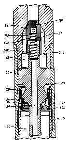
includes a first, a
second and a third valve pressure surface. The first valve pressure surface
engages an internal
surface of a housing of the down-the-hole drilling apparatus and is in
communication with a drive
chamber of the down-the-hole drilling apparatus. The second valve pressure
surface is in
communication with a high pressure port of the down-the-hole drilling
apparatus. The third valve
pressure surface is in communication with a passageway extending through a
distributor within
the housing. The apparatus also includes a valve passageway extending through
the pressure
reversing valve which is in communication with a first volume of the down-the-
hole drilling
apparatus. The first volume is formed by surfaces of the distributor and the
third valve pressure
surface.
[0005] In accordance with a second preferred embodiment, the present
invention provides a
pressure reversing valve assembly for a down-the-hole drilling apparatus
comprising a housing, a
distributor and a valve. The distributor is housed within the housing and
includes an exhaust
stem, a central bore extending axially through the distributor, and a
plurality of apertures
1
CA 02742024 2011-06-03
extending radially through the exhaust stem. The valve is sealingly engaged
with the exhaust
stem and movable between an open position and a closed position. In the open
position, a high
pressure port is in communication with a drive chamber. In the closed
position, the high pressure
port is sealed off from the drive chamber. The valve includes a first valve
pressure surface, a
second valve pressure surface, a third valve pressure surface, and a valve
passageway that extends
through the valve and is in communication with a first volume of the down-the-
hole drilling
apparatus. The first volume is formed by surfaces of the distributor and at
least one of the first,
second and third valve pressure surfaces.
[0006] In accordance with a third preferred embodiment, the present
invention provides a
pressure reversing valve assembly for a down-the-hole drilling apparatus
comprising a distributor
and a valve. The distributor includes an upper body portion, a lower body
portion having a side
wall, and an exhaust stem extending distally from the lower body portion. The
valve includes a
base, a side wall and a valve passageway. The base has a proximal surface, a
distal surface and a
thru hole for receiving the exhaust stem. The side wall extends from the base
and has an inner
side surface and an outer side surface. The valve passageway extends through
the valve and is in
communication with an area formed by the distributor and the proximal surface
of the base.
BRIEF DESCRIPTION OF THE SEVERAL VIEWS OF THE DRAWINGS
[0007] The foregoing summary, as well as the following detailed
description of the invention,
will be better understood when read in conjunction with the appended drawings.
For the purpose
of illustrating the invention, there are shown in the drawings embodiments
which are presently
preferred. It should be understood, however, that the invention is not limited
to the precise
arrangements and instrumentalities shown.
[0008] In the drawings:
[0009] Fig. 1 is a perspective view of a DHD hammer in accordance
with a first preferred
embodiment of the present invention;
[0010] Fig. 2 is an enlarged perspective view of a backhead of the
DHD hammer of Fig. 1;
[0011] Fig. 3 is a cross-sectional, elevational view of the backhead
of Fig. 2;
[0012] Fig. 4 is a perspective view of a check valve of the DHD
hammer of Fig. 1;
[0013] Fig. 5 is a cross-sectional, elevational view of the check
valve of Fig. 4;
[0014] Fig. 6 is a perspective view of a distributor of the DHD hammer of
Fig. 1;
[0015] Fig. 7 is a cross-sectional, elevational view of the
distributor of Fig. 6;
2
CA 02742024 2011-06-03
[0016] Fig. 8 is a cross-sectional, elevational view of the
distributor of Fig. 6 with the cross-
section taken through the through holes of the distributor;
[0017] Fig. 9 is an enlarged perspective view of a valve of the DHD
hammer of Fig. 1;
[0018] Fig. 10 is a cross-sectional, elevational view of the valve of
Fig. 9;
[0019] Fig. ills a partial, cross-sectional, elevational view of the DHD
hammer of Fig. 1
with the check valve in the closed position and a valve in the open position;
[0020] Fig. 12 is an enlarged, partial, cross-sectional, elevational
view of the DHD hammer of
Fig. 11 with the valve in the open position and the cross-section taken
through the through holes
of the distributor;
[0021] Fig. 13 is a partial, cross-sectional, elevational view of the DHD
hammer of Fig. 1
with the valve in a closed position and the cross-section taken through the
through holes of the
distributor;
[0022] Fig. 14 is an enlarged, partial, cross-sectional, elevational
view of the DHD hammer of
Fig. 13 with the valve in the closed position and the cross-section taken
through the distributor;
[0023] Fig. 14A is a greatly enlarged partial view of the valve/distributor
interface of Fig. 14;
[0024] Fig. 15 is an enlarged, partial, cross-sectional, elevational
view of a valve and a
distributor of a DHD hammer in accordance with a second preferred embodiment;
and
[0025] Fig. 16 is a enlarged, partial, cross-sectional, elevational
view of a valve and a
distributor of a DHD hammer in accordance with third preferred embodiment of
the present
invention.
DETAILED DESCRIPTION OF THE INVENTION
[0026] Certain terminology is used in the following description for
convenience only and is
not limiting. The words "right," "left," "upper," and "lower" designate
directions in the drawings
to which reference is made. For purposes of convenience, "distal" is generally
referred to as
toward the drill bit end of the DHD hammer, and "proximal" is generally
referred to as toward the
backhead end of the DHD hammer as illustrated in Fig. 1. Additionally, the
term "a," as used in
the specification, means "at least one." The terminology includes the words
above specifically
mentioned, derivatives thereof, and words of similar import.
[0027] In a first preferred embodiment, the present invention
provides a DHD hammer 10, as
best shown in Figs. 1-14. The DHD hammer 10 generally includes a housing 12,
drill bit 13, a
piston 14, a backhead 16 and a check valve assembly 18, as best shown in Figs.
1, 11 and 13. The
3
CA 02742024 2011-06-03
backhead 16 and the piston 14 are assembled to the housing 12 in a
conventional manner that is
well known to those skilled in the art. As such, a detailed discussion of the
assembly of the
backhead 16 and the piston 14 to the DHD hammer 10 is not necessary for
complete
understanding of the present invention.
[0028] However, the backhead 16 is configured as shown in Figs. 2 and 3
with a tool-joint
connection for connecting to a drill string (not shown). The tool-joint
connection includes male
threads 16a. The backhead 16 also includes threads 16b for threadedly
connecting to the housing
12 (Fig. 11). A supply port 20 extends through the backhead 16 and is in
communication with an
interior 16c of the backhead 16 (Fig. 3).
[0029] The check valve assembly 18 (Fig. 11) includes a check valve 19, a
biasing member
21, and a distributor 22. The check valve 19 is configured, as best shown in
Figs. 4 and 5, and is
operatively assembled to the distributor 22, as best shown in Fig. 11. The
check valve 19
includes a closed proximal end 19a and an open distal end 19b. The check valve
19 also includes
an interior 19c having a radially inwardly extending distal surface 19d about
a proximal end of
the interior 19c. The check valve 19 can also optionally include a gland 19e
for receiving a seal
19f (Fig. 11).
[0030] The distributor 22 is configured, as best shown in Figs. 6-8,
and is positioned within
the housing 12, as best shown in Fig. 11. The distributor 22 includes a stem
24, an upper body
portion 26, a lower body portion 28, and an exhaust stem 32. The distributor
22 also includes a
central bore 34 and a plurality of apertures 36. The central bore 34 extends
axially through the
distributor 22 about a central axis of the distributor 22. The plurality of
apertures 36 are
circumferentially spaced apart and extend in the radial direction from an
interior surface of the
central bore 34 to an outer surface of the exhaust stem 32 about its proximal
end. The plurality of
apertures 36 allow for fluid communication radially through the exhaust stem
32.
[0031] The stem 24 extends proximally from the upper body portion 26. The
stem 24 has an
outside diameter that is smaller than the outside diameter of the upper body
portion 26. The stem
24 also includes a radially inwardly extending flange 24a about a mid portion
along the length of
the stem 24.
[0032] The upper body portion 26 has an outside diameter that is
slightly undersized
compared to the inside diameter of the housing 12, to fit within the housing
12 without significant
play. The upper body portion 26 includes a through hole 26a (Fig. 8) extending
axially through
the upper body portion 26 from a proximal surface 26b to a distal surface 26c
of the upper body
4
CA 02742024 2011-06-03
portion 26. Preferably, the upper body portion 26 includes a plurality of
circumferentially spaced
through holes 26a and more preferably, six (6) through holes 26a that are
circumferentially and
evenly spaced apart. The through holes 26a allow for fluid communication from
a region above
the upper body portion 26 to a region below the upper body portion 26. The
distal surface 26c of
the upper body portion 26 also engages a proximal end 12d of an inner housing
12a (also known
as and referred to as a cylinder), while the proximal surface 26b engages a
distal end 16d of the
backhead 16, when assembled within the housing 12 (Fig. 11). The assembly of
the distributor 22
between the proximal end 12d of the inner housing 12a and the distal end 16d
of the backhead 16
secures the position of the distributor 22 within the housing 12.
[0033] The inner housing 12a is a preferably a separate component of the
housing 12 that is
assembled to the housing 12 in a conventional manner known in the art.
However, the inner
housing 12a can be integrally formed as part of the housing 12 instead of
being a separate
component assembled thereto.
[0034] The lower body portion 28 of the distributor 22 is configured
to be substantially
frustroconical with a side wall 30 that extends downwardly from a distal
surface 28a of the
frustroconical portion of the lower body portion 28. The lower body portion 28
also includes a
distal surface 28b that extends radially inwardly from the side wall 30.
[0035] The exhaust stem 32 extends distally from a bottom portion of
the lower body portion
28. The apertures 36 are located about the proximal end of the exhaust stem
32. Preferably, the
exhaust stem 32 includes a plurality of apertures 36 and more preferably, four
(4) apertures 36
that are circumferentially and evenly spaced apart.
[0036] Referring to Fig. 11, when assembled, the check valve 19
slidingly engages with the
stem 24 of the distributor 22. The check valve 19 is biased to a closed
position (Fig. 11) to seal
off the supply port 20 extending through the backhead 16. The check valve 19
is biased to the
closed position by the biasing member 21, such as a compression spring. The
biasing member 21
is positioned between the check valve 19 and the stem 24 within an interior
19c of the check
valve 19 and an interior 24b of the stem 24. Specifically, the biasing member
21 has a proximal
end that engages the distal surface 19d of the check valve 19 and a distal end
that engages the
radially inwardly extending flange 24a.
[0037] The DHD hammer 10 also includes a valve 38, as best shown in Figs. 9-
11. The valve
38 is generally configured as an inverted cap, as shown in Fig. 9 having a
substantially "U"
shaped cross-section, as shown in Fig. 10. The valve 38 includes a base 48 and
a side wall 50
5
CA 02742024 2011-06-03
extending from the base 48. The side wall 50 has an inner side surface 50a and
an outer side
surface 50b. The base 48 includes a through hole 48c that extends through a
central portion of the
base 48. The valve 38 also includes a first valve pressure surface 40, a
second valve pressure
surface 42, a third valve pressure surface 44, and a valve passageway 46.
[0038] The base 48 can be configured with an overall outside diameter
ODbase that is
substantially the same as the overall outside diameter of the side wall 50
Opside wall- The base 48,
however, is preferably configured with an overall outside diameter ODbase that
is larger than the
overall outside diameter of the side wall 50 Opside wall. The larger ODbase
advantageously provides
a means to control the rate of flow passing through the first passageway
without restricting the
flow of working fluids to other areas of the DHD hammer 10 in communication
with a volume
bounded by the side wall 50.
[0039] The first valve pressure surface 40 is a distal surface of the
base 48. The first valve
pressure surface 40 is also configured to be in communication with the drive
chamber 58. The
second valve pressure surface 42 is a proximal surface of the side wall 50.
The second valve
pressure surface 42 is also configured to be in communication with a high
pressure port of the
DHD hammer 10, as further described below. The third valve pressure surface 44
is a proximal
surface of the base 48. The third valve pressure surface 44 is also configured
to be in
communication with a passageway formed by and extending through the central
bore 34 that
extends through the distributor 22 via aperture 36 that extends radially
through the exhaust stem
32, as further described below.
[0040] The valve passageway 46 is generally configured as a through
hole that extends from
at least one of an inner side surface 50a of the side wall 50 and the third
valve pressure surface 44,
to the first valve pressure surface 40. That is, the valve passageway 46
includes a proximal end,
and a distal end that extends radially outwardly and distally from its
proximal end. The distal end
of the valve passageway 46 is configured to completely engage with an upper
surface 12c of the
annular rib 12b when the valve 38 is in a closed position (Fig. 14). The upper
surface 12c is an
internal surface of the housing 12. Preferably, the valve 38 includes a
plurality of valve
passageways 46 and more preferably, four (4) valve passageways 46 that are
circumferentially
and equally spaced apart.
[0041] The valve 38 can optionally include a gland 53 about the through
hole 48c and a gland
55 about an inner side surface 50a of the side wall 50. The glands 53 and 55
are configured to
receive seals 54, 56 respectively, as shown in Fig. 11. The seals 54, 56 can
be e.g., an 0-ring seal
6
CA 02742024 2011-06-03
made from an elastomeric material or any other material readily known in the
art suitable for its
intended purpose. As shown in Fig. 11, the seal 54 is positioned between the
exhaust stem 32 and
the base 48 to provide sealing engagement between the base 48 and the exhaust
stem 32. The seal
56 is positioned between the side wall 30 of the lower body portion 28 and the
side wall 58 of the
valve 38 to provide sealing engagement between the side wall 30 and the side
wall 58.
[0042] The valve 38 is assembled within the DHD hammer 10 and to the
distributor 22, as
best shown in Fig. 11. The valve 38 and the distributor 22 are located within
the housing 12. The
housing 12 includes an inner housing 12a that receives the lower body portion
28 of the
distributor 22 and the valve 38. The inner housing 12a includes an annular rib
12b that extends
radially inwardly from about an upper region of the inner housing 12a. The
inner housing 12a
can e.g., be a cylinder with porting features, as readily known in the art.
[0043] The valve 38 is assembled to the distributor 22 such that the
through hole 48c receives
the exhaust stem 32 while the side wall 50 receives the lower body portion 28
of the distributor
22. In the assembled state, the valve 38 is located above the annular rib 12b.
[0044] The valve 38 is configured to sealingly engage with the exhaust stem
32 and is
movable between an open position (Fig. 11) and a closed position (Fig. 13). In
the open position,
as best shown in Fig. 12, the drive chamber 58 is in communication with the
supply port 20. That
is, the valve 38 allows working fluids to flow through the supply port 20,
around the check valve
assembly 18, down through the through hole 26a of the distributor 22 and
around the valve 38,
passing between the first valve pressure surface 40 and the upper surface 12c
of the annular rib
12b and into the drive chamber 58. The flow path just described represents a
first passageway
leading from the supply port 20 to the drive chamber 58. The first passageway
is also referred to
as a high pressure port of the DHD hammer 10, because high pressure working
fluids are fed to
the DHD hammer 10 therethrough.
[0045] Furthermore, in the open position, the valve 38 is sealingly engaged
with the exhaust
stem 32 such that an upper portion of the inner side surface 48d sealingly
engages apertures 36 of
the exhaust stem 32. That is, the inner side surface 48d completely covers the
plurality of
apertures 36.
[0046] The assembly of the valve 38 to the distributor 22 also forms
a first volume 52 that is
bounded by the valve 38 and a distal surface 28b of the distributor 22. The
first volume 52 is in
communication with the valve passageway 46. Further, in the open position, the
first volume 52
is in communication with the drive chamber 58 via the valve passageway 46.
7
CA 02742024 2011-06-03
[0047] The first volume 52 and cross-sectional flow area through the
valve passageway 46 is
preferably configured to have a ratio of [volume (inches3)]:[area (inches2)]
of about 20 to 40. It is
this ratio that advantageously allows a user to adjust and control the timing
of the opening and
closing of the valve 38 and therefore, control and adjust the overall
efficiency of the DHD
hammer 10. The cross-sectional flow area through the valve passageway 46 can
be adjusted, for
example, by increasing the number of valve passageways 46 formed through the
valve 38 or by
adjusting the overall diameter of an individual valve passageway 46.
[0048] When in the closed position, as best shown in Fig. 14, the
high pressure port is sealed
off from the drive chamber 58. That is, the valve 38 moves distally until the
first valve pressure
surface 40 engages with the upper surface 12c of the annular rib 12b i.e., an
internal surface of the
housing 12. In this position, the first passageway is closed off and the
distal end of the valve
passageway 46 is sealed off by the upper surface 12c. Furthermore, the
proximal end of the base
48 moves distally to partially expose the apertures 36, thereby allowing
communication between
the first volume 52 and the central bore 34 of the distributor 22. That is,
the second passageway
permits communication between the first volume 52 and the drive chamber 58
when the valve 38
is in the closed position. The apertures 36 advantageously allow for the
release of pressurized
working volumes within the first volume 52 to be discharged through the
distributor 22, such that
the valve 38 can be moved proximally and repositioned to the open position, as
further described
below.
[0049] The assembly of the valve 38 and the distributor 22 provides the
first passageway
permitting fluid communication between the high pressure port and the drive
chamber 58, as
described above. The assembly of the valve 38 and the distributor 22 also
provides a second
passageway permitting fluid communication between the first volume 52 and the
drive chamber
58 when the valve 38 is in the open position. The second passageway extends
through the valve
passageway 46. Lastly, the assembly of the valve 38 and the distributor 22
provides for a third
passageway permitting fluid communication between the first volume 52 and the
central bore 34
of the distributor 22, when the valve 38 is in the closed position. The third
passageway extends
through the aperture 36.
[0050] In operation, the piston 14 (as best shown in Fig. 13) moves
reciprocatively within the
DHD hammer 10, as a result of the operation of the valve 38 and working fluid
volumes supplied
to the DHD hammer 10 via the supply port 20 and first passageway.
Specifically, the piston 14
cycles between a return position, wherein the piston 14 is at its most
proximal position within the
8
CA 02742024 2011-06-03
DHD hammer 10, and an impact position, wherein the distal end of the piston 14
impacts the drill
bit 13. The movement of the piston 14 from the impact position to the return
position is referred
to as the return cycle. The movement of the piston 14 from the return position
to the impact
position is referred to as the drive cycle.
100511 During the return cycle, the vale 38 is in the closed position.
However, as the piston
14 reaches the return position during the return cycle, the pressure within
the drive chamber 58
builds up owing to the decreased volume or volume contraction of the drive
chamber 58 during
the return cycle. This pressure build up applies forces on the first valve
pressure surface 40 to
move the valve 38 to the open position.
[0052] When the valve 38 moves to the open position, the first passageway
opens up to
provide high pressure working volumes to the drive chamber 58 and drive the
piston 14 towards
the impact position (i.e., initiation of the drive cycle). As the piston 14
moves distally during the
drive cycle, the drive chamber 58 is pressurized via the first passageway and
the first volume 52
is pressurized via the second passageway. However, the first volume 52 is
significantly smaller
than the drive chamber 58 volume and thus pressurizes at a faster rate than
the drive chamber 58.
Moreover, as the piston 14 moves distally, the drive chamber 58 volume
expands, and once the
piston 14 moves past the distal end of the exhaust stem 32, the pressure
within the drive chamber
58 exhausts through the piston's central bore. The resulting combination of
the expanding drive
chamber 58 volume and subsequent exhausting of the drive chamber 58 fluids
results in a
pressure differential between the pressure within the first volume 52 and the
pressure within the
drive chamber 58 to move the valve 38 from the open position to the closed
position (Fig. 13).
Owing to the configuration of the first volume 52, the rate of flow through
the valve passageway
46 or the overall cross-sectional flow area through the valve passageway 46,
and the drive cycle
of the piston 14, the valve 38 closes after the piston 14 moves distally about
50 % to 90 %, and
preferably, about 70 % to 80 % of the total drive cycle length. Then, after
the piston 14 reaches
the impact position, the drive and return cycles repeat with the foregoing
described opening and
closing of the valve 38.
[00531 Fig. 15 illustrates a valve 138 in accordance with a second
preferred embodiment of
the present invention. The valve 138 is configured substantially the same as
the valve 38 of the
first preferred embodiment, except for a valve passageway 146. The valve
passageway 146 is
configured to extend from at least one of the third valve pressure surface 144
and an inner side
surface 150a of side wall 150 to an outer side surface 150b of the valve 138.
Preferably, the valve
9
CA 02742024 2013-01-11
passageway 146 is a substantially horizontal valve passageway. The valve
passageway 146
allows fluid communication between a first volume 152 and the high pressure
port when the valve
138 is in either a closed or open position.
[0054] Fig. 16 illustrates a valve 238 in accordance with a third
preferred embodiment of the
present invention. The valve 238 is configured substantially the same as the
valve 38 and the
valve 138 of the first and second preferred embodiments, except for a valve
passageway 246. The
valve passageway 246 is configured to extend from at least one of a third
valve pressure surface
244 and an inner side surface 250a of the valve 238 and a distal end of the
valve 238. That is, the
valve passageway 246 extends to the first valve pressure surface 240.
Preferably, the valve
passageway 246 is a substantially vertical passageway or parallel to the
central bore 34 of the
distributor 22. As such, the valve passageway 246 allows for fluid
communication between a first
volume 252 to the drive chamber 58 when the valve 238 is in either in a closed
or an open
position. That is, the distal end of the valve passageway 246 is positioned
spaced apart from the
upper surface 12c of the annular rib 12b, such that the valve passageway 246
is not sealed or
covered by the inner housing 12a when in the closed position.
[0055] The operation of the valves 138, 238 of the second and third
preferred embodiments
operates substantially the same as the valve 38 of the first preferred
embodiment.
[0056] The scope of the claims should not be limited by the preferred
embodiment set forth in
the examples, but should be given the broadest interpretation consistent with
the description as a
whole.