Language selection

Search

Patent 2742250 Summary

Third-party information liability

Some of the information on this Web page has been provided by external sources. The Government of Canada is not responsible for the accuracy, reliability or currency of the information supplied by external sources. Users wishing to rely upon this information should consult directly with the source of the information. Content provided by external sources is not subject to official languages, privacy and accessibility requirements.

Claims and Abstract availability

Any discrepancies in the text and image of the Claims and Abstract are due to differing posting times. Text of the Claims and Abstract are posted:

  • At the time the application is open to public inspection;
  • At the time of issue of the patent (grant).
(12) Patent: (11) CA 2742250
(54) English Title: MOUSE HOLE DAMPER DEVICE
(54) French Title: DISPOSITIF D'AMORTISSEMENT DE TROU DE SOURIS
Status: Granted and Issued
Bibliographic Data
(51) International Patent Classification (IPC):
  • E21B 19/14 (2006.01)
  • E21B 19/00 (2006.01)
(72) Inventors :
  • PEDERSEN, JAN ERIK (Norway)
(73) Owners :
  • GRANT PRIDECO, INC.
(71) Applicants :
  • GRANT PRIDECO, INC. (United States of America)
(74) Agent: SMART & BIGGAR LP
(74) Associate agent:
(45) Issued: 2016-11-08
(86) PCT Filing Date: 2009-10-26
(87) Open to Public Inspection: 2010-05-06
Examination requested: 2014-07-04
Availability of licence: N/A
Dedicated to the Public: N/A
(25) Language of filing: English

Patent Cooperation Treaty (PCT): Yes
(86) PCT Filing Number: PCT/NO2009/000369
(87) International Publication Number: WO 2010050821
(85) National Entry: 2011-04-29

(30) Application Priority Data:
Application No. Country/Territory Date
20084569 (Norway) 2008-10-30

Abstracts

English Abstract


A mouse hole damper device (1) positioned at the bottom portion (4) of a
mouse hole pipe (2), the mouse hole damper (1) being arranged to dampen an
impact
from an object (28) falling in the mouse hole pipe (2), and the mouse hole
damper (1) including
a material (36) which has been worked into forming walls around elongated
openings (34), and the material (36) being arranged in such a way that the
openings (34)
are, in the main, parallel to the longitudinal axis (13) of the mouse hole
pipe (2).


French Abstract

L'invention porte sur un dispositif d'amortissement de trou de souris (1), positionné à la partie inférieure (4) d'un tuyau de trou de souris (2), l'amortisseur de trou de souris (1) étant agencé de façon à amortir un impact à partir d'un objet (28) tombant dans le tuyau de trou de souris (2), et l'amortisseur de trou de souris (1) renfermant un matériau (36) qui a été travaillé sous la forme de parois de formation autour d'ouvertures allongées (34), et le matériau (36) étant agencé d'une telle manière que les ouvertures (34) sont principalement parallèles à l'axe longitudinal (13) du tuyau de trou de souris (2).

Claims

Note: Claims are shown in the official language in which they were submitted.

Claims:
1. A mouse hole damper device positioned at the bottom portion of a mouse
hole pipe, the mouse hole damper device being arranged to dampen an impact
from an object which is falling in the mouse hole pipe, the mouse hole damper
device comprising:
a material which has been worked into forming walls around elongated
openings, the material being arranged in such a way that the openings are
substantially parallel to the longitudinal axis of the mouse hole pipe;
a guide configured to guide the object toward a centre axis of the mouse hole
damper device; and
a distributor configured to distribute forces applied to the mouse hole damper
device, wherein the distributor includes an upper plate, a lower plate, and an
intermediate piece extending between the upper plate and the lower plate.
2. The device according to claim 1, wherein a wall thickness of the worked
material is smaller than 0.1 times the width of an adjacent opening.
3. The device according to claim 1, wherein a wall thickness of the worked
material is less than 0.05 times the width of an adjacent opening.
4. The device according to claim 1, wherein the worked material is formed
as a
damper element with a plurality of elongated openings.
5. The device according to claim 1, wherein at least two damper elements
are
placed on top of each other in the direction of the longitudinal axis of the
mouse
hole pipe.
6. The device according to claim 1, wherein the at least two damper
elements
which are placed on top of each other are dissimilar with respect to
retardation
6

properdes.
7. The device according to claim 1, wherein a cross section of the worked
material has at least a honeycomb structure or a round core which is made of
corrugated aluminum.
8. The device according to claim 1, wherein the worked material is rolled
up into
a roll forming a damper element.
9. The device according to claim 1, wherein the worked material is encased
in a
casing material.
10. The device according to claim 9, wherein the casing material is para-
aramid
fiber.
11. A mouse hole pipe, the mouse hole damper device being arranged to
dampen
an impact from an object which is falling in the mouse hole pipe, the mouse
hole
damper device comprising:
a plurality of damper elements comprising a material which has been worked
into forming walls around elongated openings, wherein each of the openings is
substantially parallel to the mouse hole pipe: a guide configured to guide the
object
toward the damper elements; and
a distributor configured to distribute forces applied to the damper elements;
wherein the plurality of damper elements are arranged one on top of the
other;
wherein the distributor comprises an upper plate, a lower plate, and an
intermediate piece extending between the upper and lower plates.
12. The device according to claim 11, wherein the guide is configured to
guide
the object toward a centre axis of the mouse hole damper.
7

13. The device according to claim 11, wherein a wall thickness of the
worked
material is smaller than 0.1 times the width of an adjacent opening.
14. The device according to claim 11, wherein a wall thickness of the
worked
material is less than 0.05 times the width of an adjacent opening.
15. The device according to claim 11, wherein the at least two of the
plurality of
damper elements are dissimilar with respect to retardation properties.
16. The device according to claim 11, wherein a cross section of the worked
material has at least a honeycomb structure or a round core which is made of
corrugated aluminum.
17. The device according to claim 11, wherein at least one damper element
is
formed from rolling the worked material into a roll.
18. The device according to claim 11, wherein the worked material is
encased in
a casing material.
19. The device according to claim 18, wherein the casing material is para-
aramid
fiber.
8

Description

Note: Descriptions are shown in the official language in which they were submitted.


CA 02742250 2011-04-29
WO 2010/050821 PCT/N02009/000369
1
MOUSE HOLE DAMPER DEVICE
This invention relates to a mouse hole damper. More particu-
larly, it relates to a mouse hole damper positioned in the
lower portion of a mouse hole, the mouse hole damper being
arranged to dampen the impact from an object falling in the
mouse hole.
So-called mouse holes, which are often arranged in a drilling
floor, are used when adding and removing pipe sections. The
mouse hole typically includes a mouse hole pipe extending
io downwards from an opening in the drilling floor, the mouse
hole pipe being arranged to guide and also intermediately
store a pipe which is in the mouse hole. Several coordinate
mouse hole pipes may be arranged for a common mouse hole
opening, the mouse hole pipes being arranged to be moved into
position below the actual mouse hole opening.
If a pipe is dropped during work in the mouse hole, there may
be a risk that the impact energy, as the bottom portion of
the mouse hole pipe is hit, is sufficient for the falling
pipe to break through the bottom portion and continue fal-
ling.
It is known to arrange a mouse hole damper at the lower por-
tion of the mouse hole, that is to say at the bottom portion
of the mouse hole pipe. According to the prior art, a mouse
hole damper includes a relatively complicated and expensive

CA 02742250 2011-04-29
WO 2010/050821 2 PCT/N02009/000369
structure which must be replaced after having been activated.
The invention has for its object to remedy or reduce at least
one of the drawbacks of the prior art.
The object is achieved according to the invention through the
features which are specified in the description below and in
the claims that follow.
A mouse hole damper has been provided, which is located at
the bottom portion of a mouse hole pipe, the mouse hole
damper being arranged to dampen an impact from an object fal-
io ling in the mouse hole. The mouse hole damper is character-
ized by including a material which has been worked into form-
ing walls around elongated openings, the material being
arranged in such a way that the openings are, in the main,
parallel to the longitudinal axis of the mouse hole.
A falling object striking against the worked material is re-
tarded by the velocity energy deforming the worked material.
The wall thickness of the worked material may be less than
0.1 times the width of opening of an adjacent opening. If de-
sirable, the wall thickness of the worked material may be
less than 0.05 times the width of opening of an adjacent
opening.
The worked material may be formed as a damper element with a
plurality of elongated openings.
A damper element may be designed to provide a desired retar-
dation profile. By retardation profile is meant the energy
absorbed as a function of length of deformation. The retarda-
tion profile is dependent on, inter alia, the wall thickness
of the worked material, the proportion of the cross-sectional
area of the damper element filled with worked material, and

CA 02742250 2011-04-29
WO 2010/050821 3 PCT/N02009/000369
the firmness and deformation properties of the worked mate-
rial. As is known, a worked material with relatively thin
walls will have a longer way of deformation when absorbing a
certain amount of energy than a material with thicker walls.
s A damper element may include several different worked materi-
als.
At least two damper elements may be placed on top of each
other in the direction of the longitudinal axis of the mouse
hole. By choosing worked materials with different deformation
properties for the different damper elements, the deformation
profile may be controlled in form and value within a rela-
tively wide range.
The worked material may be rolled up into forming a damper
element, for example from a sheet, in which two layers of
worked material in a corrugated form constitute the surface
of the plate. The elongated openings are between the layers.
Other manufacturing methods may include extrusion, for exam-
ple.
The worked material may have a honeycomb structure in cross
section. Materials having a honeycomb structure are rela-
tively easily available and well suited for the purpose.
Among other possible cross-sectional shapes, curved cross
sections may be mentioned, such as circular or oval ones, or
other polygonal cross sections such as quadrilateral or oc-
tagonal ones. It is also relevant to have a round core of
corrugated aluminium.
The mouse hole damper may include a load distributor, for ex-
ample in the form of a plate which is placed over the damper
element and which is arranged to distribute the force from a
falling object over as much of the cross section of the
damper element as possible.

CA 02742250 2011-04-29
WO 2010/050821 4 PCT/N02009/000369
The mouse hole damper may be provided with a guide which is
arranged to guide the object in towards the centre axis of
the damper element before the object gets into contact with
the load distributor.
The load distributor and guide may form part of a lift in the
mouse hole pipe. This lift, which is often arranged to adjust
the height of a bottom stop in the mouse hole pipe, is often
termed a "rabbit".
The device according to the invention provides a relatively
cost-effective mouse hole damper in which the deformation
profile of the damper can easily be adjusted to the prevail-
ing conditions.
In what follows is described an example of a preferred em-
bodiment which is visualized in the accompanying drawings, in
which:
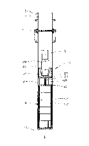
Figure 1 shows a mouse hole damper in accordance with the
invention;
Figure 2 shows a section I-I of figure 1;
Figure 3 shows, on a larger scale and in perspective, a
damper element; and
Figure 4 shows, on a still larger scale, a section of figure
3.
In the drawings, the reference numeral 1 indicates a mouse
hole damper which is connected to the bottom portion 4 of a
mouse hole 2 by means of a flange connection 6.
The mouse hold damper 1 includes a pipe portion 8 which is
connected to the flange connection 6 and provided, at its op-
posite end portion, with an end cover 10.

CA 02742250 2011-04-29
WO 2010/050821 5 PCT/N02009/000369
A number of damper elements 12 are placed on top of each
other parallel to the common centre axis 13 of the damper 1
and mouse hole pipe 2. The damper elements 12 are placed in a
sleeve-shaped holder 14, thus forming an easily replaceable
cartridge 16.
A distributor 18 is disposed above the cartridge 16, the dis-
tributor 18, which includes two disc-shaped plates 20 with an
intermediate piece 22, being arranged to distribute a force
over the cross section of the cartridge 16 and thereby over
the cross section of the damper elements 12.
A guide 24 with a centric conical opening 26 is placed above
the distributor 18 and arranged to guide a falling object 28,
here in the form of a drill pipe, in towards the centre axis
13.
In this preferred embodiment, the damper element 12 is rolled
up from a plate 30, see figure 3, and the damper element 12
is then enveloped in a casing material 32, here in the form
of kevlar.
In figure 4 is shown each layer in which elongated openings
34 are surrounded by worked material 36.
If an object 28 falls into the mouse hole pipe 2, the object
28 is guided by means of the guide 24 in towards the centre
axis 13 before impacting. The force from the impact is trans-
mitted via the distributor 18 to the cartridge 16 with the
damper elements 12. The damper elements 12 deform to differ-
ent extents according to their resistance to deformation.
The energy from the impact is thereby absorbed by the damper
elements 12. The falling object 28 is stopped without causing
any harm to other equipment or personnel.

Representative Drawing
A single figure which represents the drawing illustrating the invention.
Administrative Status

2024-08-01:As part of the Next Generation Patents (NGP) transition, the Canadian Patents Database (CPD) now contains a more detailed Event History, which replicates the Event Log of our new back-office solution.

Please note that "Inactive:" events refers to events no longer in use in our new back-office solution.

For a clearer understanding of the status of the application/patent presented on this page, the site Disclaimer , as well as the definitions for Patent , Event History , Maintenance Fee  and Payment History  should be consulted.

Event History

Description Date
Maintenance Request Received 2024-09-04
Maintenance Fee Payment Determined Compliant 2024-09-04
Inactive: Recording certificate (Transfer) 2023-02-16
Inactive: Recording certificate (Transfer) 2023-01-16
Inactive: Multiple transfers 2022-12-06
Common Representative Appointed 2019-10-30
Change of Address or Method of Correspondence Request Received 2018-01-12
Grant by Issuance 2016-11-08
Inactive: Cover page published 2016-11-07
Pre-grant 2016-09-21
Inactive: Final fee received 2016-09-21
Letter Sent 2016-04-07
Notice of Allowance is Issued 2016-04-07
Inactive: Approved for allowance (AFA) 2016-03-31
Inactive: QS passed 2016-03-31
Amendment Received - Voluntary Amendment 2015-10-01
Inactive: S.30(2) Rules - Examiner requisition 2015-06-04
Inactive: Report - No QC 2015-05-29
Letter Sent 2014-07-14
Request for Examination Received 2014-07-04
All Requirements for Examination Determined Compliant 2014-07-04
Request for Examination Requirements Determined Compliant 2014-07-04
Amendment Received - Voluntary Amendment 2014-07-04
Inactive: Cover page published 2011-07-05
Inactive: Notice - National entry - No RFE 2011-06-21
Application Received - PCT 2011-06-20
Inactive: IPC assigned 2011-06-20
Inactive: First IPC assigned 2011-06-20
National Entry Requirements Determined Compliant 2011-04-29
Application Published (Open to Public Inspection) 2010-05-06

Abandonment History

There is no abandonment history.

Maintenance Fee

The last payment was received on 2016-09-30

Note : If the full payment has not been received on or before the date indicated, a further fee may be required which may be one of the following

  • the reinstatement fee;
  • the late payment fee; or
  • additional fee to reverse deemed expiry.

Please refer to the CIPO Patent Fees web page to see all current fee amounts.

Owners on Record

Note: Records showing the ownership history in alphabetical order.

Current Owners on Record
GRANT PRIDECO, INC.
Past Owners on Record
JAN ERIK PEDERSEN
Past Owners that do not appear in the "Owners on Record" listing will appear in other documentation within the application.
Documents

To view selected files, please enter reCAPTCHA code :


To view images, click a link in the Document Description column. To download the documents, select one or more checkboxes in the first column and then click the "Download Selected in PDF format (Zip Archive)" or the "Download Selected as Single PDF" button.

List of published and non-published patent-specific documents on the CPD .

If you have any difficulty accessing content, you can call the Client Service Centre at 1-866-997-1936 or send them an e-mail at CIPO Client Service Centre.


Document
Description 
Date
(yyyy-mm-dd) 
Number of pages   Size of Image (KB) 
Claims 2015-10-01 3 91
Representative drawing 2011-06-22 1 5
Description 2011-04-29 5 181
Drawings 2011-04-29 2 72
Claims 2011-04-29 2 50
Abstract 2011-04-29 2 61
Cover Page 2011-07-05 2 37
Representative drawing 2016-10-24 1 5
Cover Page 2016-10-24 1 35
Confirmation of electronic submission 2024-09-04 3 80
Notice of National Entry 2011-06-21 1 196
Reminder - Request for Examination 2014-06-30 1 116
Acknowledgement of Request for Examination 2014-07-14 1 175
Commissioner's Notice - Application Found Allowable 2016-04-07 1 161
PCT 2011-04-29 8 338
Amendment / response to report 2015-10-01 10 391
Final fee 2016-09-21 1 51