Note: Descriptions are shown in the official language in which they were submitted.
CA 02742353 2012-12-03
1
DESCRIPTION
Title of Invention
CONTINUOUS CASTING APPARATUS FOR STEEL
TECHNICAL FIELD
[0001]
The present invention relates to a continuous casting apparatus for steel
which
supplies molten steel into a casting mold to manufacture a cast.
15 BACKGROUND ART
[0002]
In a continuous casting process for steel, for example, application of a
direct
current magnetic field to molten steel discharged into a casting mold is
performed for the
purpose of quality improvement of a cast. It is known that a counterflow
toward the
direction opposite to a main stream is generated around a discharge flow of
molten steel
in this direct current magnetic field.
[0003]
In normal continuous casting of molten steel, as shown in FIG. 7 for example,
a
submerged entry nozzle 102 which discharges molten steel 100 into a casting
mold 101 is
used. Discharge holes 103 which are pointed downward with respect to the
horizontal
direction are formed at two locations in the vicinity of a lower end of a side
face of the
CA 02742353 2011-04-29
2
submerged entry nozzle 102. Also, in order to clean the inside of the
submerged entry
nozzle 102, the molten steel 100 is discharged into the casting mold 101 from
the
discharge holes 103 while blowing non-oxidized gas such as Ar gas (argon gas).
In a
case where a direct current magnetic field is applied to a discharge flow 104
of the
molten steel 100 discharged from the discharge holes 103 by for example an
electromagnetic brake device (not shown), a counterflow 105 in the opposite
direction is
generated around the discharge flow 104. As a result, Ar gas bubbles 106
contained in
the discharge flow 104 do not easily deeply enter the molten steel 100 within
the casting
mold 101 due to this counterflow 105. As a result, the number of the Ar gas
bubbles
106 can be reduced inside a cast obtained by casting the molten steel 100.
[0004]
However, since the Ar gas bubbles 106 flow on the counterflow 105 which rises
along the submerged entry nozzle 102, is concentrated around the submerged
entry
nozzle 102 and floats to a meniscus 107, the bubbles may not be removed by the
meniscus 107. In this case, some of the Ar gas bubbles 106 are trapped by a
solidified
shell 108 formed on the internal surface of the casting mold 101. As a result,
the
number of the Ar gas bubbles 106 in the surface layer of a cast obtained by
casting the
molten steel 100 is increased.
[0005]
Thus, in order to prevent the Ar gas bubbles 106 from being trapped by the
solidified shell 108 of the casting mold 101, electromagnetically stirring the
molten steel
100 in the vicinity of the meniscus 107 in the upper part of the casting mold
101 is
proposed. With this electromagnetic stirring, a stirring flow 109 is formed as
shown in
FIG 8 for example, in the molten steel 100 in the vicinity of the meniscus
107; therefore,
the Ar gas bubbles 106 trapped by the solidified shell 108 can be reduced
(refer to Patent
CA 02742353 2011-04-29
3
Document 1).
[Prior Art Documents]
[Patent Documents]
[0006]
[Patent Document 1] Japanese Unexamined Patent Application, First Publication
No. 2000-271710
[Summary of Invention]
[Problems to be Solved by the Invention]
[0007]
However, even in a case where the electromagnetic stirring is used together as
described above, the number of the Ar gas bubbles 106 in the surface layer of
the cast
could not be sufficiently reduced. When the present inventors studied the
cause of this,
it was found that the Ar gas bubbles 106 are trapped by the solidified shell
108 formed on
a long side wall 101a in an area 110 between the long side wall 101a of the
casting mold
101, and the submerged entry nozzle 102. As described above, although the Ar
gas
bubbles 106 rise along the submerged entry nozzle 102 while flowing on the
counterflow
105, some of the Ar gas bubbles 106 are diffused while rising. As a result, as
shown in
FIG 9 for example, since the space between the long side wall 101a and the
submerged
entry nozzle 102 is narrow, the Ar gas bubbles 106 will be trapped by the
solidified shell
108 on the long side wall 101a. Additionally, as shown in FIG 8, since the
space
between the long side wall 101a and the submerged entry nozzle 102 is narrow,
even
when the stirring flow 109 is formed by the electromagnetic stirring, the
molten steel 100
will not easily flow through the area 110. As a result, the Ar gas bubbles 106
in the
molten steel 100 in the area 110 tend to be trapped by the solidified shell
108 on the long
CA 02742353 2012-12-03
4
side wall 101a.
[0008]
Since the Ar gas bubbles 106 in the area 110 remain on the surface layer of a
cast in this way and causes degradation in the strength of the cast or surface
roughness in
the cast, there is a demand of improvement in the quality of the cast.
[0009]
The present invention has been made in view of the above circumstances, and
has an object of providing a continuous casting apparatus for steel which can
reduce Ar
gas bubbles contained in a cast made by continuous casting, and can improve
the quality
of the cast.
DISCLOSURE OF INVENTION
[0010]
In order to solve the above problems and achieve the relevant object, the
present
invention adopted the following measures. That is,
(1) a continuous casting apparatus for steel of the present invention
includes: a casting
mold for casting a molten steel, having a pair of long side walls and a pair
of short side
walls; a submerged entry nozzle which discharges the molten steel into the
casting mold;
an electromagnetic stirring device arranged along each of the long side walls
to stir an
upper part of the molten steel within the casting mold; and an electromagnetic
brake
device arranged below the electromagnetic stirring device to impart a direct
current
magnetic field in a casting mold thickness direction which is along the short
side walls,
the direct current magnetic field having a flux density distribution which is
uniform in a
casting mold width direction which is along each of the long side walls. A
curved
portion which is curved toward the electromagnetic stirring device is formed
at least at a
position where the curved portion faces the submerged entry nozzle on each of
CA 02742353 2013-04-05
the long side walls. The horizontal distance between a top of the curved
portion and the
submerged entry nozzle in plan view is equal to or more than 35 mm and less
than 50
mm. The curved portion is formed in an internal surface of each of the long
side walls.
The external surface of each of the long side walls is a flat surface. And the
curved
5 portion is formed at a top central position of the internal surface of
each of the long side
walls.
[0011]
According to the continuous casting apparatus for steel as described in the
above
(1), the curved portion is formed at least at a position where the curved
portion faces the
submerged entry nozzle on each of the long side walls of the casting mold.
Thus,
curved regions can be formed between the curved portions and the submerged
entry
nozzle. Since the curved regions can be made wider than conventional regions
formed
between flat walls and a submerged entry nozzle due to formation of the curved
portion,
a region where the Ar gas bubbles in the molten steel rising along the outer
periphery of
the submerged entry nozzle and being diffused can be wider.
Meanwhile, when the present inventors carried out an investigation, it was
found
that trapping of Ar gas bubbles by the solidified shell formed on the long
side walls of
the casting mold catmot be suppressed only by forming the curved region.
Specifically,
when the horizontal distance between the top of the curved portion and the
submerged
entry nozzle in plan view is less than 35 mm, the flow of the molten steel
flows less
easily in the curved region, and the Ar gas bubbles in the molten steel tend
to be trapped
by the solidified shell. Additionally, when the horizontal distance is equal
to or greater
than 50 mm, it would be difficult to secure the uniform flow of the molten
steel in the
curved region, and the Ar gas bubbles in the molten steel tend to be trapped
by the
solidified shell in a region where the flow velocity of the molten steel is
slow. In this
CA 02742353 2013-04-05
6
point, according to the present invention, the curved regions are formed such
that the
horizontal distance becomes equal to or more than 35 mm and less than 50 mm.
Therefore, even when the Ar gas bubbles in the molten steel which rise along
the
submerged entry nozzle are diffused, the Ar gas bubbles can float to a
meniscus.
Accordingly, the Ar gas bubbles can be inhibited from being trapped by the
solidified
shell formed on the long side wall of the casting mold. Additionally, since
the
horizontal distance can be secured by the curved regions, a stirring flow of
the molten
steel formed by the electromagnetic stirring device easily flows through this
curved
regions. As a result, the Ar gas bubbles are stirred in the upper part of the
casting mold,
and can be further inhibited from being trapped by the solidified shell. In
this way,
since trapping of the Ar gas bubbles in the solidified shell can be inhibited,
the Ar gas
bubbles contained in the cast can be reduced, and the quality of the cast can
be improved.
[0012]
In the continuous casting apparatus for steel as described in the above (1),
the
curved portion may be formed by curving each of the long side walls outward in
the
entirety thereof. Alternatively, it is preferable that the curved portion be
formed in an
internal surface of each of the long side walls, and the external surface of
each of the
long side walls be a flat surface.
Also in the continuous casting appearatus as described the above (1), in a
case
where the curved portion is formed at the internal surface of each of the long
side walls,
the distance between the curved portion and the electromagnetic stirring
device becomes
shorter than the distance between portions other than the curved portion of
the long side
wall, and the electromagnetic stirring device. Then, the molten steel in the
curved
region between the curved portion and the submerged entry nozzle can be easily
stirred.
Accordingly, since the Ar gas bubbles in the molten steel in the curved region
can be
CA 02742353 2013-04-05
6a
sufficiently stirred, even if the Ar gas bubbles float along the outer
periphery of a
submerged entry nozzle, the Ar gas bubbles in the curved region can be further
inhibited
from being trapped by the solidified shell.
[Effect of the Invention]
CA 02742353 2011-04-29
7
[0013]
According to the present invention, Ar gas bubbles contained in the cast can
be
reduced, and the quality of the cast can be improved.
BRIEF DESCRIPTION OF THE DRAWINGS
[0014]
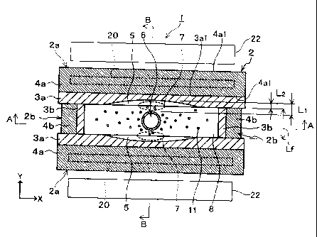
FIG 1 is a plan sectional view showing a schematic configuration in the
vicinity
of a casting mold of a continuous casting apparatus related to one embodiment
of the
present invention.
FIG 2 is a view showing the schematic configuration in the vicinity of the
casting mold of the continuous casting apparatus, and is also a vertical
sectional view
along an arrow A-A of FIG 1.
FIG 3 is a view showing the schematic configuration in the vicinity of the
casting mold of the continuous casting apparatus, and is also a vertical
sectional view
along an arrow B-B of FIG. 1.
FIG 4 is a view illustrating the flow of molten steel in a casting mold upper
part
when an electromagnetic stirring device of the continuous casting apparatus is
operated,
and is also a plan sectional view equivalent to FIG 1.
FIG 5 is a view illustrating a direct current magnetic field when an
electromagnetic brake device of the continuous casting apparatus is operated,
and is also
a plan sectional view equivalent to FIG 1.
FIG 6 is a view illustrating the flow of a direct current magnetic field,
induced
current, and counterflow when the electromagnetic brake device is operated,
and is also a
sectional view equivalent to an upper portion of FIG 2.
FIG. 7 is a vertical sectional view showing a schematic configuration in the
CA 02742353 2011-04-29
8
vicinity of a casting mold of a conventional continuous casting apparatus.
FIG 8 is a view showing the schematic configuration in the vicinity of the
casting mold, and is a plan sectional view along an arrow C-C of FIG 7.
FIG 9 is a view showing the schematic configuration in the vicinity of the
casting mold, and is a vertical sectional view along an arrow D-D of FIG 7.
BEST MODE FOR CARRYING OUT THE INVENTION
[0015]
Hereinafter, one embodiment of a continuous casting apparatus for steel of the
present invention will be described.
FIG 1 is a plan sectional view showing a schematic configuration in the
vicinity
of a casting mold of a continuous casting apparatus 1 related to one
embodiment of the
present invention, and FIGS. 2 and 3 are vertical sectional views showing the
configuration in the vicinity of the casting mold of the continuous casting
apparatus 1.
As shown in FIG 1, the continuous casting apparatus 1 has a casting mold 2
whose plan cross-sectional shape is rectangular. The casting mold 2 has a pair
of long
side walls 2a and a pair of short side walls 2b. Each of the long side walls
2a is fonned
by a copper plate 3a provided on the inside and a stainless steel box 4a
provided on the
outside. Additionally, each of the short side walls 2b is formed by a copper
plate 3b
provided on the inside and a stainless steel box 4b provided on the outside.
In addition,
in the present embodiment, the length Lf (casting thickness) of the short side
wall 2b is,
for example, 50 mm to about 300 mm.
Meanwhile, the required width of casts is, about 50 mm to 80 mm for a cast
having a thin width, is about 80 mm to 150 mm for a cast having a middle
width, and is
about 150 mm to 300 mm for a cast having a normal width.
CA 02742353 2011-04-29
9
Additionally, the horizontal direction (X direction in FIGS. 1 to 3) along the
long side wall 2a is referred to as a casting mold width direction, and the
horizontal
direction (Y direction in FIGS. 1 to 3) along the short side wall 2b is
referred to as a
casting mold thickness direction.
[0016]
A curved portion 5 which is curved toward the stainless steel box 4a (outside
of
the casting mold 2) is formed at a center position in the casting mold width
direction, in
the internal surface of the copper plate 3a of the long side wall 2a.
The curved portion 5 is formed at a position where the curved portion faces a
submerged entry nozzle 6 (to be described leter) provided within the casting
mold 2.
Additionally, when it is seen in vertical sectional views shown in FIGS. 2 and
3, the
curved portion 5 is formed so as to overlap with the submerged entry nozzle 6
and
extends downward from an upper end of the copper plate 3a. The position of the
lower
end of the curved portion 5 may be the same height as the position of the
lower end of the
submerged entry nozzle 6, or may be a position lower than the position of the
lower end
of the submerged entry nozzle 6. In addition, the curved portion 5 is formed,
for
example, by shaving off the internal surface of the copper plate 3a in the
shape of a
concave curve. Also, a curved region 7, as shown in FIG 1, is formed between
the
curved portion 5 and the submerged entry nozzle 6.
In addition, it is recommended that the horizontal distance L1 between the
curved top of the curved portion 5 and the submerged entry nozzle 6, when the
casting
mold 2 is seen in plan view, is preferably equal to or more than a
predetermined distance,
for example, equal to or more than 35 mm, in a viewpoint of securing a
distance such that
the Ar gas bubbles 11 which will be described below are not trapped by
solidified shells
26. This is because, if the horizontal distance L1 is less than 35 mm, the
flow of the
CA 02742353 2011-04-29
molten steel 8 flows less easily in the curved region 7, and the Ar gas
bubbles 11 within
the molten steel 8 tend to be trapped by the solidified shells 26.
Additionally, it is
recommended that the horizontal distance L1 is less than 50 mm. This is
because, if the
horizontal distance L1 is equal to or more than 50 mm, it would be difficult
to secure the
5 uniform flow of the molten steel 8 in the curved region 7, the flow
velocity of the molten
steel 8 would be slow, and the Ar gas bubbles 11 in the molten steel 8 twould
be trapped
easily by the solidified shells 26.
Additionally, the curving distance L2 (the shortest horizontal distance
between
the curved top and both ends in the curved portion 5, and also the shave-off
depth to form
10 the curved portion 5) of the curved portion 5 is not particularly
specified if a
predetermined distance can be secured for the horizontal distance L1, and is
appropriately
determined according to the external diameter of the submerged entry nozzle 6
or the
thickness of the casting mold 2. Here, it is preferable that the curving
distance L2 of the
curved portion 5 be smaller in a viewpoint of preventing distortion while
drawing a cast.
In addition, in the present embodiment, the difference (L1-L2) between the
horizontal
distance L1 and the curving distance L2 becomes less than a predetermined
distance (for
example, less than 40 mm). Additionally, an external surface 3a1 of the copper
plate 3a
of the long side wall 2a and both surfaces 4a1 of the stainless steel box 4a
are formed
flat.
[0017]
As shown in FIGS. 2 and 3, the submerged entry nozzle 6 is provided in an
upper position within the casting mold 2. A lower part of the submerged entry
nozzle 6
is submerged within the molten steel 8 within the casting mold 2. Discharge
holes 9
which discharge the molten steel 8 obliquely downward into the casting mold 2
are
formed in two places in the vicinity of a lower end of the lateral side of the
submerged
CA 02742353 2011-04-29
11
entry nozzle 6. The discharge holes 9 are formed so as to face the short side
walls 2b of
the casting mold 2. The Ar gas bubbles 11 or the like for cleaning the inside
of the
submerged entry nozzle 6 are contained in a discharge flow 10 discharged from
each of
the discharge holes 9.
[0018]
As shown in FIGS. 1 to 3, a pair of electromagnetic stirring devices 20 such
as
electromagnetic stirring coils, is provided at the height in the vicinity of
the height of the
meniscus 12, within the stainless steel boxes 4a of the long side walls 2a of
the casting
mold 2. Each electromagnetic stirring device 20 is arranged so as to be
parallel to both
the surfaces 4a1 of the stainless steel box 4a.
As shown in FIG 4, the molten steel 8 in the vicinity of the meniscus 12
within
the casting mold 2 can be circulated (i.e., the molten steel 8 in plan view is
circulated
about the submerged entry nozzle 6) in the horizontal direction by the
electromagnetic
stirring of the electromagnetic stirring device 20 to form a stirring flow 21.
Meanwhile,
the curved region 7 is formed so as to be wider than a conventional region
formed by a
flat wall which forms a linear shape in plan view, as much as the curved
portion.
Therefore, the flow of the molten steel will not stagnate between each long
side wall and
the submerged entry nozzle unlike the related art, and the stirring flow 21 is
circulated
around the submerged entry nozzle 6 along the internal surfaces of the long
side wall 2a
and the short side wall 2b. Additionally, the distance D1 between the curved
top of the
curved portion 5 and the electromagnetic stirring device 20 when the casting
mold 2 is
seen in a plan sectional view becomes shorter than the distance D2 between
portions
other than the curved portion 5 of the internal surface of the copper plate
3a, and the
electromagnetic stirring device 20. As a result, since the molten steel 8 in
the curved
region 7 is close to the electromagnetic stirring device 20 in addition to the
fact that the
CA 02742353 2011-04-29
12
curved region 7 will not be narrow as a flow channel for the stirring flow 21,
the molten
steel tends to be stirred more compared to the related art.
[0019]
As shown in FIG 2, a pair of electromagnetic brake devices 22, such as
electromagnets, is provided below the electromagnetic stirring devices 20. The
position
of the centerline of each electromagnetic brake device 22 (position of a
maximum
magnetic flux density) is located below the discharge holes 9 of the submerged
entry
nozzle 6.
As shown in FIG 5, the electromagnetic brake device 22 is provided outside the
long side wall 2a of the casting mold 2. As shown in FIGS. 5 and 6, the
electromagnetic brake device 22 applies a direct current magnetic field 23,
which has a
flux density distribution which is substantially uniforni in the casting mold
width
direction (the X direction in FIG 5) along the internal surface of the long
side wall 2a of
the casting mold 2, to the discharge flow 10 of the molten steel 8 immediately
after being
discharged from the discharge holes 9, in the casting mold thickness direction
(the Y
direction in FIG 5) along the internal surface of the short side 2b of the
casting mold 2.
An induced current 24, as shown in FIG 6, is generated in the casting mold
width
direction (the X direction in FIG 6) along the internal surface of the long
side wall 2a of
the casting mold 2 by the direct current magnetic field 23 and the discharge
flow 10 of
the molten steel 8 discharged from the discharge holes 9. In addition, a
counterflow 25
is formed in the direction opposite to the discharge flow 10, in the vicinity
of the
discharge flow 10 by the induced current 24 and the direct current magnetic
field 23.
The counterflow 25 moves toward and collides with the submerged entry nozzle 6
at
almost the same angle as the discharge angle of the discharge flow 10, and
rises to the
meniscus 12 along the outer peripheral surface of the submerged entry nozzle
6.
CA 02742353 2011-04-29
13
[0020]
In addition, as shown in FIGS. 2 and 3, the solidified shell 26 is formed on
the
internal surface of the casting mold 2, in which the molten steel 8 was cooled
and
solidified.
[0021]
The continuous casting apparatus 1 related to the present embodiment is
configured as described above. Next, a continuous casting method for the
molten steel
8 using the continuous casting apparatus 1 will be described.
[0022]
First, the molten steel 8 is discharged into the casting mold 2 from the
discharge
holes 9 of the submerged entry nozzle 6 while blowing Ar gas into the
submerged entry
nozzle 6. Since the molten steel 8 is discharged obliquely downward from the
discharge
holes 9, the discharge flow 10 is formed which heads from the discharge holes
9 toward
the short side wall 2b of the casting mold 2. The Ar gas bubbles 11 are
contained in the
discharge flow 10, and the Ar gas bubbles 11 float in the molten steel 8
within the casting
mold 2.
[0023]
The molten steel 8 is discharged from the submerged entry nozzle 6, and
simultaneously, the electromagnetic brake device 22 is operated. The
counterflow 25 in
the direction opposite to the flow of the discharge flow 10 is formed by the
direct current
magnetic field 23 formed by the electromagnetic brake device 22. The
counterflow 25
rises toward the meniscus 12 after colliding with the submerged entry nozzle
6. Also,
the Ar gas bubbles 11 which are floating in the molten steel 8 also flow on
the
counterflow 25, and float to the vicinity of the meniscus 12.
[0024]
CA 02742353 2011-04-29
14
Simultaneously with the operation of the above-described electromagnetic brake
device 22, the electromagnetic stirring device 20 is also operated. The
stirring flow 21
is formed in the molten steel 8 in the vicinity of the meniscus 12 within the
casting mold
2 by the electromagnetic stirring by the electromagnetic stirring device 20.
Then, the Ar
gas bubbles 11 which have flowed on the counterflow 25 and have floated to the
vicinity
of the meniscus 12 are circulated around the submerged entry nozzle 6 by the
stirring
flow 21, and are incorporated and removed into continuous casting powder (not
shown)
which has melting oxides for example, without being trapped by the solidified
shell 26
on the casting mold 2.
[0025]
Thereafter, the molten steel 8 from which the Ar gas bubbles 11 have been
removed in this way is solidified and is casted into a cast.
[0026]
According to the present embodiment described above, the curved region 7 is
formed between the curved portion 5 and the submerged entry nozzle 6 by
forming the
curved portion 5 at the top central position of the long side wall 2a of the
casting mold 2.
Since the horizontal distance L1 is secured by the curved region 7, even when
the Ar gas
bubbles 11 which flow on the counterflow 25 and rise along with the submerged
entry
nozzle 6 are diffused, the Ar gas bubbles 11 can float to the meniscus 12.
Accordingly,
the Ar gas bubbles 11 can be kept away from the solidified shell 26 formed on
the
internal surfaces of the long side wall 2a of the casting mold 2, and can be
inhibited from
being trapped by the solidified shell 26. That is, as shown in FIGS. 2 and 3,
since the
curved portion 5 forms a curved concave surface which spreads vertically
upward from
the lower position of the submerged entry nozzle 6, two curved regions 7 which
spread
vertically upward from the lower position of the submerged entry nozzle 6 are
formed
CA 02742353 2011-04-29
between the submerged entry nozzle 6 and the respective long side walls 2a.
Also, since the horizontal distance L1 is secured by the formation of the
curved
regions 7, the stirring flow 21 formed by the electromagnetic stirring device
20 tends to
flow easily in the curved regions 7. As a result, the Ar gas bubbles 11 are
stirred in the
5 upper part of the casting mold 2, and can be further inhibited from being
trapped by the
solidified shell 26. Since the Ar gas bubbles 11 can be inhibited from being
trapped by
the solidified shell 26 in this way, the Ar gas bubbles 11 contained in a cast
can be
reduced, and the quality of the cast can be improved.
[0027]
10 Additionally, since the curved portion 5 is formed in the internal
surface of the
copper plate 3a of the long side wall 2a, and the external surface of the
copper plate 3a is
formed as a flat surface, the distance DI between the curved top of the curved
portion 5
and the electromagnetic stirring device 20 becomes shorter than the distance
D2 between
the internal surface of the copper plate 2a outside the curved portion 5 and
the
15 electromagnetic stirring device 20. As a result, although the molten
steel 8 in the
curved region 7 has to pass through a narrow channel as for the stirring flow
21, the
molten steel can be simultaneously stirred easily. Accordingly, since the Ar
gas bubbles
11 in the molten steel 8 in the curved region 7 can be sufficiently stirred
within the
casting mold 2, even when the Ar gas bubbles 11 float along the outer
peripheral surface
of the submerged entry nozzle 6, the Ar gas bubbles 11 of the curved region 7
can be
further inhibited from being trapped by the solidified shell 26.
[0028]
Additionally, with the direct current magnetic field 23 applied by the
electromagnetic brake device 22, the counterflow 25 in the direction opposite
to the
discharge flow 10 discharged from the discharge holes 9 into the casting mold
2 is
CA 02742353 2011-04-29
16
formed in the vicinity of the discharge flow 10. Thereby, the Ar gas bubbles
11 in the
discharge flow 10 do not enter the molten steel 8 in the casting mold 2
deeply. As a
result, the Ar gas bubbles 11 contained inside a cast can be reduced.
[Example 1]
[0029]
Hereinafter, the effects of removing Ar gas bubbles contained in molten steel
when the continuous casting apparatus for steel of the present invention is
used will be
described. In the present example, the continuous casting apparatus 1
previously shown
in FIGS. 1 to 3 is used as the continuous casting apparatus for steel. In
addition, in the
present example, the effects of removing inclusions contained in molten steel
in addition
to the Ar gas bubbles were also evaluated.
[0030]
As for the casting mold 2 of the continuous casting apparatus 1, a casting
mold
having the width of 1200 mm, the height of 900 mm, and the thickness of 250 mm
was
used. A vertical portion (not shown) whose length is 2.5 m and a bent portion
(not
shown) whose bending radius is 7.5 m are provided in this order from the top
below the
casting mold 2.
The electromagnetic stirring device 20 is 150 mm in the height and is 100 mmFe
in thrust, and the upper end thereof is provided at the same height position
as the
meniscus 12.
The electromagnetic brake device 22 is provided such that the centerline
position thereof (namely, a position for a maximum magnetic flux density) is
set to a
position where is 500 mm depth from the meniscus 12.
Low-carbon aluminum-killed steel was used as the molten steel 8, and casting
of
steel was performed under the conditions that casting velocity is 2 rn/min
(0.033 in/sec).
CA 02742353 2011-04-29
17
A nozzle having the external diameter of 150 mm and the internal diameter of
90
mm was used as the submerged entry nozzle 6. The center positions of the
discharge
holes 9 of the submerged entry nozzle 6 are provided at the same depth
position of 300
mm from the meniscus 12. Two circular discharge holes 9 are formed in the
submerged
entry nozzle 6 so as to face the short side walls 2b of the casting mold 2.
The diameter
of the discharge holes 9 is 60 mm, and the discharge angle 0 of the discharge
holes 9 is
30 degrees downward from the horizontal surface as seen in the vertical
section of FIG 2.
Additionally, when the discharge holes are seen in plan view, the discharge
directions of
the two discharge holes 9 are mutually opposite directions of 180 degrees
around the
centerline of the submerged entry nozzle 6.
[0031]
In the continuous casting apparatus 1 described above, casting of steel was
conducted under five conditions where the horizontal distances L1 between the
curved
top of the curved portion 5 of the casting mold 2, and the submerged entry
nozzle 6 are
30 mm, 35 mm, 40 mm, 45mm, and 50 mm.
Additionally, in a case where the horizontal distance L1 is 30 mm, the curving
distance L2 of the curved portion 5 was changed between 0 mm and 5 mm; and in
a case
where the horizontal distance L1 is equal to or more than 35 min, the curving
distance L2
was changed to 5 mm, 10 mm, 15 mm, and 20 mm in correspondence with changes in
the
horizontal distance LI. Moreover, the curving distance L2 of 0 mm indicates a
state
where the curved portion 5 is not formed in the long side wall 2a of the
casting mold 2.
Also, in the casted casts, the number of the Ar gas bubbles 11 and inclusions
which have a diameter of 100 im or more and are contained in a surface layer
with a
depth of 50 mm from each surface was counted. This counting is perfoimed to
confirm
the influence on the quality of the casts, of the Ar gas bubbles and
inclusions which have
CA 02742353 2011-04-29
18
a diameter of 100 p.m or more contained in the surface layer with a depth of
50 mm from
the surface of each cast.
[0032]
The results when casting was performed under the above conditions are shown
in Table 1. In Table 1, the index of the number of the Ar gas bubbles shows
the ratio of
the number of Ar gas bubbles under the respective conditions when the number
of Ar gas
bubbles in a case where the horizontal distance L1 is 30 mm and the curving
distance L2
is 0 mm (that is, the curved portion 5 is not formed) is defined as 1.
Additionally, the
index of number of inclusions shows the ratios of the number of inclusions
under the
respective conditions when the number of inclusions in a case where the
horizontal
distance L1 is 30 mm and the curving distance L2 is 0 MM is defined as 1.
[0033]
As shown in Table 1, in a case where the horizontal distance L1 is 30 mm, it
was
found that, even when the curved portion 5 is formed with the curving distance
L2 being
5 mm, both the index of the number of Ar gas bubbles and the index of number
of
inclusions are still 1, and the number of Ar gas bubbles and inclusions cannot
be reduced.
Additionally, in a case where the horizontal distance L1 is 50 mm, even when
the
curved portion 5 is formed with the curving distance L2 being 20 mm, the index
of the
number of Ar gas bubbles becomes very close to 1, and the index of the number
of
inclusions becomes larger than 1. Hence, it was found that the number of Ar
gas
bubbles and inclusions cannot be sufficiently reduced.
[0034]
On the other hand, in a case where the horizontal distance L1 is 35 mm, 40 mm,
and 45 mm, and the curved portion 5 is ft:allied, it was confirmed that the
index of the
number of Ar gas bubbles and the index of number of inclusions become less
than 1 and
CA 02742353 2011-04-29
19
the number of Ar gas bubbles and inclusions is reduced. Accordingly, it was
found that,
when molten steel was casted using the continuous casting apparatus of the
present
invention, Ar gas bubbles and inclusions can be appropriately removed, and the
quality of
a cast can be improved.
[0035]
[Table 1]
Distance betvveen
Curving Distance of
Curved Portion and Index of Number of Index of Number of
Curved Portion L2,
Submerged entry mm Ar Gas Bubbles Inclusions
nozzle, L1 (mm) ( )
30 0 1 1
30 5 1 1
35 5 0.5 0.6
40 10 0.2 0.3
45 15 0.1 0.2
50 20 0.9 1.1
[0036]
The technical scope of the present invention is not limited to the
above-described embodiment only, and various modifications of the above-
described
embodiment may be made without departing from the concept of the present
invention.
That is, the specific processing and configurations mentioned in the present
embodiment
are no more than examples and can be appropriately changed.
For example, in the continuous casting apparatus for steel of the present
invention, each of the long side walls 2a may be curved to the outside of the
casting mold
2 in the entirety thereof, thereby forming the curved portion 5.
INDUSTRIAL APPLICABILITY
[0037]
According to the present invention, it is possible to provide a continuous
casting
CA 02742353 2011-04-29
apparatus for steel which can reduce Ar gas bubbles contained in a cast which
has been
continuously casted, and can improve the quality of the cast.
[Description of Reference Symbols]
[0038]
5 1: CONTINUOUS CASTING APPARATUS
2: CASTING MOLD
2a: LONG SIDE WALL
2b: SHORT SIDE WALL
3a, 3b: COPPER PLATE
10 4a, 4b: STAINLESS STEEL BOX
5: CURVED PORTION
6: SUBMERGED ENTRY NOZZLE
7: CURVED REGION
8: MOLTEN STEEL
15 9: DISCHARGE HOLE
10: DISCHARGE FLOW
11: Ar GAS BUBBLE
12: MENISCUS
20: ELECTROMAGNETIC STIRRING DEVICE
20 21: STIRRING FLOW
22: ELECTROMAGNETIC BRAKE DEVICE
23: DIRECT CURRENT MAGNETIC FIELD
24: INDUCED CURRENT
25: COUNTERFLOW
26: SOLIDIFIED SHELL