Language selection

Search

Patent 2742371 Summary

Third-party information liability

Some of the information on this Web page has been provided by external sources. The Government of Canada is not responsible for the accuracy, reliability or currency of the information supplied by external sources. Users wishing to rely upon this information should consult directly with the source of the information. Content provided by external sources is not subject to official languages, privacy and accessibility requirements.

Claims and Abstract availability

Any discrepancies in the text and image of the Claims and Abstract are due to differing posting times. Text of the Claims and Abstract are posted:

  • At the time the application is open to public inspection;
  • At the time of issue of the patent (grant).
(12) Patent: (11) CA 2742371
(54) English Title: MOUNTING ARRANGEMENT FOR A V-ROD IN A VEHICLE SUSPENSION
(54) French Title: AMENAGEMENT DE MONTAGE POUR UNE TIGE EN V DANS UNE SUSPENSION DE VEHICULE
Status: Deemed Expired
Bibliographic Data
(51) International Patent Classification (IPC):
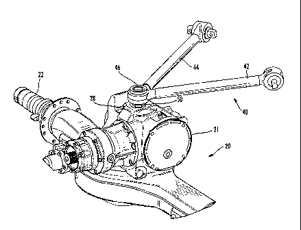
  • B60G 9/00 (2006.01)
(72) Inventors :
  • ELLIOTT, MATT T. (United States of America)
  • WINDERS, MARK (United States of America)
(73) Owners :
  • VOLVO TRUCK CORPORATION
(71) Applicants :
  • VOLVO TRUCK CORPORATION (Sweden)
(74) Agent: NORTON ROSE FULBRIGHT CANADA LLP/S.E.N.C.R.L., S.R.L.
(74) Associate agent:
(45) Issued: 2016-02-23
(86) PCT Filing Date: 2008-11-05
(87) Open to Public Inspection: 2010-05-14
Examination requested: 2013-10-23
Availability of licence: N/A
Dedicated to the Public: N/A
(25) Language of filing: English

Patent Cooperation Treaty (PCT): Yes
(86) PCT Filing Number: PCT/US2008/012493
(87) International Publication Number: US2008012493
(85) National Entry: 2011-05-02

(30) Application Priority Data: None

Abstracts

English Abstract


A mounting arrangement for a V-rod in a vehicle suspension includes an axle
housing having a mounting cavity
formed thereon and a joint member installed in the mounting cavity so that a
joint coupling extends outward from the axle
housing. The joint member may include a ball joint mounted on a post mountable
in the mounting cavity. The mounting cavity may be
formed in a boss provided on the axle housing.


French Abstract

Un aménagement de montage destiné à une tige en V dans une suspension de véhicule comprend un carter dessieux sur lequel est formée une cavité de montage et qui comporte un élément darticulation installé dans la cavité de montage de sorte quun accouplement par articulation sétende vers lextérieur depuis le carter dessieux. Lélément darticulation peut comprendre une articulation sphérique montée dans un montant pouvant être monté dans la cavité de montage. La cavité de montage peut être formée dans un bossage situé sur le carter dessieux.

Claims

Note: Claims are shown in the official language in which they were submitted.

What is claimed is:
1. A mounting arrangement for a V-rod in a vehicle suspension, comprising:
an axle
housing having a mounting cavity formed thereon, wherein the mounting cavity
is provided
with a threaded lower part and an unthreaded upper part, the upper part being
wider than the
lower part;
a ball joint post installed in the mounting cavity so that a joint coupling
extends outward
from the axle housing, wherein the ball joint post includes a threaded end
portion and an
unthreaded portion, the unthreaded portion being wider than the threaded
portion, the
threaded portion being engageable in the threaded lower part of the mounting
cavity; and
a bolt that secures the joint coupling to the ball joint post.
2. The mounting arrangement as recited in claim 1, wherein: the unthreaded
portion of
the ball joint post and the upper part of the mounting cavity are sized for an
interference fit.
3. The mounting arrangement as recited in claim 1, wherein: the joint
coupling is a joint
ball mounted on the post.
4. The mounting arrangement as recited in claim 1, wherein: the cavity is
formed on an
upper surface of the axle housing.
5. The mounting arrangement as recited in claim 1, wherein: the axle
housing further
comprises a differential carrier, and the cavity is formed on an upper surface
of the differential
carrier.
6. The mounting arrangement as recited in claim 5, wherein: the
differential carrier
comprises a boss to accommodate the cavity.

Description

Note: Descriptions are shown in the official language in which they were submitted.


CA 02742371 2011-05-02
WO 2010/053466 PCT/US2008/012493
MOUNTING ARRANGEMENT FOR A V-ROD IN A VEHICLE SUSPENSION
Field of the invention
[0m] The invention relates to vehicle suspensions, and more particularly, to
suspensions including V-rods, that is, V-shaped structures connected between
the
vehicle frame and axle.
Background and Summary
[002] In vehicle suspensions, particularly those with air springs, it is known
to use V-
rods (also known as V-stays and V-bars) mounted between the frame and the axle
to
stabilize the axle in the lateral and fore-and-aft directions, while allowing
vertical travel.
A prior arrangement for mounting the V-rod to the axle, as disclosed in US
Patent No.
6,439,588 to Svensson, includes a plate structure mounted with four bolts on
the axle
housing. The plate supports a joint member to which the point end or vertex of
the V-
rod is attached.
[ow] When the axle is a drive axle housing, the plate is typically mounted to
the
differential carrier, that is, the portion of the axle housing containing the
gearing that
distributes driving torque from the drive shaft to the wheels.
[004] The arrangement of a mounting plate to the axle housing or differential
carrier to
support a V-rod presents difficulties. The mounting plate is a separate part,
increasing
weight and cost to the assembly. In addition, the mounting plate positions the
V-rod
joint at a height relative to the frame that may interfere with vertical
suspension travel.
[005] The invention overcomes these problems in the art with a mounting
arrangement
for a V-rod that includes a joint member mounted directly to the axle housing
in a cavity
formed therein.
[006] According to the invention, a mounting arrangement for a V-rod in a
vehicle
suspension includes an axle housing having a mounting cavity formed thereon
and a
joint member installed in the mounting cavity so that a joint coupling extends
outward
from the axle housing.

CA 02742371 2011-05-02
WO 2010/053466 PCT/US2008/012493
[007] According to an embodiment of the invention, the joint member comprises
a post
or stud installable in the mounting cavity and a joint coupling mounted on the
post.
[008] According to the invention, the mounting cavity is formed with a
threaded lower
part and an unthreaded upper part, the upper part being wider than the lower
part, and
the post includes a first threaded portion and a second unthreaded portion or
pilot, the
pilot being wider than the first threaded portion. The second portion of the
post and the
upper part of the mounting cavity are sized for an interference fit. Thus, the
threaded
portion of the post and the threaded part of the cavity align and draw the
post into the
cavity to engage the pilot and upper cavity part.
[009] According to an embodiment, the cavity is formed on an upper surface of
the axle
housing. If a differential carrier is part of the axle, the cavity is formed
on an upper
surface of the differential carrier.
[010] According to one embodiment, the joint member is a joint ball mounted on
the
post.
[011] Alternatively, the joint member is a socket member to receive a ball
joint of a V-
rod.
[012] In yet another alternative, the joint member is a bracket to receive a
bushing
member of a V-rod.
Brief Description of the Drawings
[013] The invention will be better understood by reference to the following
detailed
description read in conjunction with the appended drawings, in which:
[014] Figure 1 is a perspective view of a truck frame and axle showing a V-rod
attached between the frame and axle according to the prior art;
[015] Figure 2 is a perspective view of an axle housing with a V-rod mounting
structure
in accordance with an embodiment of the invention;
[016] Figure 3 is an exploded view of an embodiment of a joint member; and,
[017] Figure 4 is a section view of the axle housing of Figure 2 showing
internal
structure of a mounting cavity with a joint member according to the invention
installed
therein.
2

CA 02742371 2015-07-23
Detailed Description
[018] Figure 1 is a perspective view of a rear end portion of a truck frame
illustrating a
V-rod connection of the prior art. The truck frame has side rails 1 and 2
joined by a
cross members 3 and 4. An axle 11 is connected to the frame to extend
laterally
relative to the frame rails 1, 2 by a suspension apparatus including control
arms 10 and
support arms 6, 7. The support arms 6, 7 include seats 8 for air springs (not
illustrated)
which may be disposed between the support arms 6, 7 and frame rails 1, 2. The
suspension apparatus is not fully illustrated as air suspensions are familiar
to those
skilled in the art and many examples are available. The invention, while
particularly
suitable for air suspensions, is not limited to any particular air suspension,
and may be
used for other types of suspensions as well.
[019] A single axle 11 is shown in Figure 1 for simplicity; of course, a
vehicle rear axle
set up may have two or three axles.
[020] The axle 11 includes an axle housing 12 which houses the gearing that
receives
driving torque from the drive shaft (not illustrated) and distributes it to
the wheel spindles
12A, 12B for driving the wheels. A V-rod 13 is formed by two legs 15, 16
joined to form a
vertex 17. The V-rod 13 is connected at the vertex 17 to the axle housing 12
and by the
legs to the frame rails 1, 2. As is known, a V-rod provides lateral and
longitudinal
stability to the axle.
[021] The vertex 17 of the V-rod is attached to a plate 14 mounted to a
differential
carrier 18 itself mounted on the axle housing 12. The arms 15, 16 of the V-rod
are
attached by brackets 21 (one bracket is visible) to the frame rails 1, 2.
[022] Figure 2 shows in perspective view a mounting arrangement for the V-rod
to the
axle housing 20 in accordance with an embodiment of the invention. In Figure
2, the
axle housing 20 includes a differential carrier 21 mounted to an upper side of
the axle
housing. The axle housing 20 terminates with spindles 22 (only one is shown,
the
opposite end being sectioned) to support the wheels (not shown in this view).
According to the invention, a joint member 50 for the V-rod is mounted
directly to the
axle housing 20, which, in the illustrated embodiment, is directly to the
carrier 21. The
carrier 21 includes a boss or protrusion 28 formed on an outer surface to
accommodate
3

CA 02742371 2011-05-02
WO 2010/053466 PCT/US2008/012493
a mounting cavity for the joint member 50. The boss and cavity may be provided
on an
upper surface as shown in Figure 2.
[023] Figure 3 is an exploded view of a joint member 50 in accordance with the
invention. The joint member 50 includes a post 52 and a joint ball 54. The
post 52
includes a lower portion 55 having a pilot 56 and a threaded shaft 58. The
pilot 56 is
wider than the threaded shaft 58, that is, has a diameter greater than the
diameter of
the threaded shaft.
[024] An upper portion or neck 60 of the post 52 supports the joint ball 54.
The post 52
also includes a hex shaped collar 62 which allows the post to be rotated by a
tool for
installing in the boss 28, as described below. A bolt 64 inserted through a
hole 66 in the
joint ball 54 mates with a threaded hole 68 in the neck 60 to secure the joint
ball to the
post 52.
[025] Figure 4 shows the mounting arrangement of the invention in section
view. The
carrier 21 boss 28 includes a mounting cavity 70 formed as a stepped hole
having a
threaded lower part 72 and a relatively wider, unthreaded upper part 74. The
lower part
72 is sized and the threads are formed to mate with the threaded shaft 58 of
the post
52. The upper part 74 is sized to have a diameter slightly less than a
diameter of the
pilot 56 to provide an interference fit between the upper part 74 and pilot
56. As the
shaft 52 is screwed into the mounting cavity 70, the pilot 56 is drawn into
and pressed
into the upper part 74.
[026] As shown in Figure 4, the V-rod (one arm 44 being shown) is mounted to
the joint
ball 54 by a socket 80 carried on the vertex 46 of the V-rod.
[027] Alternatively, a socket can be mounted to the post and the joint ball
mounted on
the V-rod.
[028] According to yet another alternative, a bracket can be formed or mounted
on the
shaft to receive a bushing assembly mounted on the V-rod.
[029] The invention has been described in terms of preferred principles,
structure and
embodiments; however, those skilled in the art will understand that
substitutions may be
made of components described here without departing from the scope of the
invention
as recited in the following claims.
4

Representative Drawing
A single figure which represents the drawing illustrating the invention.
Administrative Status

2024-08-01:As part of the Next Generation Patents (NGP) transition, the Canadian Patents Database (CPD) now contains a more detailed Event History, which replicates the Event Log of our new back-office solution.

Please note that "Inactive:" events refers to events no longer in use in our new back-office solution.

For a clearer understanding of the status of the application/patent presented on this page, the site Disclaimer , as well as the definitions for Patent , Event History , Maintenance Fee  and Payment History  should be consulted.

Event History

Description Date
Letter Sent 2024-05-06
Letter Sent 2023-11-06
Inactive: Recording certificate (Transfer) 2022-07-20
Inactive: Multiple transfers 2022-06-14
Common Representative Appointed 2019-10-30
Grant by Issuance 2016-02-23
Inactive: Cover page published 2016-02-22
Inactive: Final fee received 2015-12-10
Pre-grant 2015-12-10
Notice of Allowance is Issued 2015-10-21
Letter Sent 2015-10-21
4 2015-10-21
Notice of Allowance is Issued 2015-10-21
Inactive: Approved for allowance (AFA) 2015-10-16
Inactive: Q2 passed 2015-10-16
Amendment Received - Voluntary Amendment 2015-07-23
Inactive: S.30(2) Rules - Examiner requisition 2015-01-27
Inactive: Report - No QC 2015-01-13
Letter Sent 2013-11-07
Request for Examination Received 2013-10-23
Request for Examination Requirements Determined Compliant 2013-10-23
All Requirements for Examination Determined Compliant 2013-10-23
Inactive: Cover page published 2011-07-06
Inactive: Notice - National entry - No RFE 2011-06-27
Inactive: First IPC assigned 2011-06-21
Inactive: IPC assigned 2011-06-21
Application Received - PCT 2011-06-21
National Entry Requirements Determined Compliant 2011-05-02
Application Published (Open to Public Inspection) 2010-05-14

Abandonment History

There is no abandonment history.

Maintenance Fee

The last payment was received on 2015-10-09

Note : If the full payment has not been received on or before the date indicated, a further fee may be required which may be one of the following

  • the reinstatement fee;
  • the late payment fee; or
  • additional fee to reverse deemed expiry.

Patent fees are adjusted on the 1st of January every year. The amounts above are the current amounts if received by December 31 of the current year.
Please refer to the CIPO Patent Fees web page to see all current fee amounts.

Owners on Record

Note: Records showing the ownership history in alphabetical order.

Current Owners on Record
VOLVO TRUCK CORPORATION
Past Owners on Record
MARK WINDERS
MATT T. ELLIOTT
Past Owners that do not appear in the "Owners on Record" listing will appear in other documentation within the application.
Documents

To view selected files, please enter reCAPTCHA code :


To view images, click a link in the Document Description column (Temporarily unavailable). To download the documents, select one or more checkboxes in the first column and then click the "Download Selected in PDF format (Zip Archive)" or the "Download Selected as Single PDF" button.

List of published and non-published patent-specific documents on the CPD .

If you have any difficulty accessing content, you can call the Client Service Centre at 1-866-997-1936 or send them an e-mail at CIPO Client Service Centre.


Document
Description 
Date
(yyyy-mm-dd) 
Number of pages   Size of Image (KB) 
Description 2011-05-01 4 189
Abstract 2011-05-01 1 67
Claims 2011-05-01 2 85
Representative drawing 2011-05-01 1 29
Drawings 2011-05-01 4 102
Cover Page 2011-07-05 2 51
Description 2015-07-22 4 185
Claims 2015-07-22 1 30
Drawings 2015-07-22 4 98
Cover Page 2016-01-28 1 48
Representative drawing 2016-02-09 1 20
Courtesy - Patent Term Deemed Expired 2024-06-16 1 530
Notice of National Entry 2011-06-26 1 196
Reminder - Request for Examination 2013-07-07 1 117
Acknowledgement of Request for Examination 2013-11-06 1 176
Commissioner's Notice - Application Found Allowable 2015-10-20 1 161
Commissioner's Notice - Maintenance Fee for a Patent Not Paid 2023-12-17 1 542
PCT 2011-05-01 11 397
Amendment / response to report 2015-07-22 5 186
Final fee 2015-12-09 2 66