Language selection

Search

Patent 2742434 Summary

Third-party information liability

Some of the information on this Web page has been provided by external sources. The Government of Canada is not responsible for the accuracy, reliability or currency of the information supplied by external sources. Users wishing to rely upon this information should consult directly with the source of the information. Content provided by external sources is not subject to official languages, privacy and accessibility requirements.

Claims and Abstract availability

Any discrepancies in the text and image of the Claims and Abstract are due to differing posting times. Text of the Claims and Abstract are posted:

  • At the time the application is open to public inspection;
  • At the time of issue of the patent (grant).
(12) Patent: (11) CA 2742434
(54) English Title: END PIECE FOR ARCUATE VOID FORMS
(54) French Title: PIECECD'EXTREMITE POUR COFFRAGES ARQUES VIDES
Status: Expired and beyond the Period of Reversal
Bibliographic Data
(51) International Patent Classification (IPC):
  • E02D 5/00 (2006.01)
(72) Inventors :
  • TURNER, MICHAEL L. (United States of America)
  • GATES, JOHN W. (United States of America)
(73) Owners :
  • MICHAEL L. TURNER
  • JOHN W. GATES
(71) Applicants :
  • MICHAEL L. TURNER (United States of America)
  • JOHN W. GATES (United States of America)
(74) Agent: PARLEE MCLAWS LLP
(74) Associate agent:
(45) Issued: 2014-01-28
(22) Filed Date: 2011-06-07
(41) Open to Public Inspection: 2011-12-11
Examination requested: 2011-06-07
Availability of licence: N/A
Dedicated to the Public: N/A
(25) Language of filing: English

Patent Cooperation Treaty (PCT): No

(30) Application Priority Data:
Application No. Country/Territory Date
12/814,287 (United States of America) 2010-06-11

Abstracts

English Abstract

A universal end wall component for closing the open side of an arcuate end or circular void form, used for creating space between expansive soils and a concrete structure, comprising, an elongated panel having crenellated upper and lower edges forming a plurality of spaced apart tabs that are bendable to form fastening surfaces for attaching the end wall component to the upper and lower panels of the void form.


French Abstract

Un composant de paroi d'extrémité universel permettant de fermer le côté ouvert d'une extrémité arquée ou d'une forme vide circulaire utilisée pour créer un espace entre des sols sujets à gonflement et une structure en béton. Il comporte un panneau allongé pourvu d'un bord supérieur et d'un bord inférieur crénelés formant une pluralité de pattes espacées qui peuvent être pliées pour former des surfaces de fixation afin de fixer le composant de paroi d'extrémité aux panneaux supérieurs et inférieurs de la forme vide.

Claims

Note: Claims are shown in the official language in which they were submitted.

CLAIMS
What is claimed is:
1. A universal end wall component for closing the open side of a
void form structure comprising,
an elongated panel having a longitudinal axis and opposed
facing surfaces, and
crenellated upper and lower edges that are parallel to the
longitudinal axis.
2. The end wall component of claim 1 and including a plurality of
spaced apart scores in one of the facing surfaces that are perpendicular to
the longitudinal axis.
3. The end wall component of claim 2 where the panel is
constructed of corrugated paper.
4. An arcuate form void for creating a space beneath a concrete
structure adjacent a curved pier, comprising,
a rectangular shell having,
a planar top member having an arcuately shaped first
edge and a plurality of second edges ,
a planar base member having an arcuately shaped first
edge and a plurality of second edges,
a plurality of side members interconnecting the mutually
parallel top and base members along their second edges,
a substantially arcuately shaped end panel having a body
portion with inside facing and outside facing surfaces and top and bottom

6
edges, said end panel disposed between the top and base members in a
position interconnecting the arcuate edges of the top and base members and
spaced inwardly therefrom, said end panel having,
a plurality of spaced apart opposing tab pairs extending
from the top and bottom edges of the end panel in a direction parallel
to the top and base panels,
means affixing said tabs to the top and bottom panels for
securing the end panel to the top and bottom members.
5. The form void of claim 4 where the end panel is scored along
spaced apart lines that are perpendicular to the top and bottom edges of the
panel.
6. The form void of claim 4 where the tabs are integral with the
body portion of the end panel.
7. The form void of claim 4 where each pair of opposing tabs
comprise an elongated strip having a longitudinal axis and terminal ends and
where each strip is attached to one of the surfaces of the arcuately shaped
panel in a position where the longitudinal axis of the strip is perpendicular
to
the top and bottom edges of the panel and the terminal ends of the strip
extend outwardly from the top and bottom edges of the panel.

Description

Note: Descriptions are shown in the official language in which they were submitted.


CA 02742434 2011-06-07
1
END PIECE FOR ARCUATE VOID FORMS
FIELD OF THE INVENTION
The present invention relates generally to void forms that create a
space between expansive soils and concrete structures that are poured in
positions over such soils. The present invention constitutes an improvement
on the arcuate end corrugated form void that is the subject matter of U.S.
Patent No. 5,915,884.
BACKGROUND OF THE INVENTION
In concrete construction where walls and slabs must be separated
from expansive soils it is necessary to support these structures with
laterally
spaced apart concrete piers that are poured in place into holes in the ground.
If the void forms for walls and slabs are put in place before the piers are
poured it is necessary that the void forms that surround the pier position be
shaped to act as a form for the portion of the pier that may extend above the
level of the ground on which the void forms are placed. Where void forms that
are intended to create a void under a poured concrete wall, grade beam or
floor slab are placed after a pier has been poured it is necessary that the
void
forms be shaped so that they correctly void the circular edge of a drilled
pier,
that is, they abut and are flush with the surface of the pier in order to
prevent
the concrete that is poured for the wall or slab from leaking into the space
between the pier and the void form.
In both cases it is essential that the void form have the same contour
as the pier to which it abuts. In the case of beam void that creates a space
between the ground and a wall the abutting void form must be arcuate in
shape. In the case of creating a void beneath a floor slab, the pier abutting
void form must be circular to surround the pier.
In practice, it is not always known, when acquiring the form void for a
construction project, what the size of the piers will be. Accordingly, the
large
area void forms for creating space beneath a floor slab and the elongated
void forms for placement under a wall to be poured must be field cut to

CA 02742434 2011-06-07
2
accommodate the particular piers encountered at the job site. Cutting an
arcuate pattern in the pre-manufactured void forms requires that a normal
side wall of the void be cut away creating an opening into the interior of the
form. Such an opening is unacceptable for several reasons. The open
unsupported cut end of the form will not adequately support the weight of the
concrete that is poured on top of the form. Further, concrete may run into the
interior of the form which negates the purpose of the void form by eliminating
the space between the wall or slab and the ground. It is therefore necessary
to create an arcuate or circular end piece that will cover the opening in the
form created by cutting the form to match the contour of the pier. Creating
and properly attaching such an end piece in the field is usually done with
scrap material and is unsatisfactory at best.
It is therefore the principal object of the invention to provide a vertically
supported radial sealed edge structure for a void form.
Another object of the invention is to provide a universal end piece that
can be custom fit in the field to any perimetric length of open ended void
form
and can be affixed to the void form easily and in a manner that will create
the
necessary loading strength for the arcuate edge of the void form.
SUMMARY OF THE INVENTION
The present invention is a universal end wall component for closing the
open side of an arcuate or circular void form structure comprising an
elongated panel of bendable material where the lengthwise top and bottom
mutually parallel edges of the panel are crenellated, forming a plurality of
integral tastening tabs projecting from the top and bottom edges of the panel.
The panel also has a plurality of spaced apart scores in one of the facing
surfaces of the panel that are perpendicular to the top and bottom edges. The
scores in the surface of the panel facilitate forming the panel into a
geometric
arc (substantially arcuate) or a convex polygonal shape. The panel is cut to a
length appropriate to the perimetric length of the open end of the void form,
whether an arc or an entire circle. At the time the end wall panel is inserted
between the flat upper and lower plates of the void form the fastening tabs

CA 02742434 2011-06-07
3
are bent ninety degrees to be parallel with the upper and lower panel
members of the void form and flush with the inside surfaces of those panels.
The tabs are then affixed to the respective panels with staples, glue or other
means.
DESCRIPTION OF THE DRAWINGS
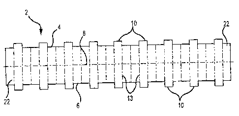
Figure 1 is a top view of the crenellated end piece panel.
Figure 2 is a perspective view of a typical beam void form with an
arcuately cut end. The interior bracing is not shown.
Figure 3 is an enlarged fragmentary perspective view of a typical beam
void form with the end piece of the present invention affixed to the arcuate
end of the void form forming an end piece closure for the void form.
DETAILED DESCRIPTION OF PREFERRED EMBODIMENT
Referring to the drawings, Figure 1 illustrates the end piece panel 2 of
the present invention. The top and bottom edges 4 and 6 are mutually parallel
and are parallel to the longitudinal axis 8 of the panel. Crenellations in the
top
and bottom edges of the panel form a plurality of projecting tabsl0.
Preferably the panel is constructed from the same material as the void form
into which it will be inserted, namely corrugated paper or plastic.
In an alternative embodiment the fastening tabs are constructed from a
plurality of elongated strips of corrugated paper or plastic material which
are
attached to the rectangularly shaped end piece panel in spaced apart and
mutually parallel configuration. The terminal ends of each strip constitute a
pair of tabs that respectively extend beyond the top and bottom edges of the
end piece panel.
An exemplary beam void form 12 for creating space between a
concrete beam or wall is shown in Figures 2 and 3. The illustrated section of
beam void is a section intended to be positioned flush with the arcuate side
of
a drilled pier. The interior of the void form comprises supporting members,
such as a honeycomb structure, as shown in U.S. Patent No. 5,915,884, but

CA 02742434 2011-06-07
4
the supporting structure forms no part of the present invention and is not
shown for clarity purposes.
In operation, the panel 2 is cut to a length that will span the perimetric
dimension 15 of the opening 16 between the upper panel member 17 and the
lower base panel membe r19 of the void form 12. The end piece panel 2 is
formed into a convex polygon or a substantially arcuate sector of such a
polygon by bending the end panel at each of a plurality of score lines 13. The
substantially arcuately formed geometric panel is inserted into the opening 16
of the void form 12 and the tabs 10 are bent ninety degrees to be flush with
the inside surfaces of the top and bottom void form panel members 17 and
19. Preferably, the tabs are attached to the upper and lower panels with
staples 20, but gluing or other forms of securement may be used. The
longitudinal ends 22 of the end panel 2 are bent along a score line 13 to be
flush with the inside surface of the respective side walls 23 and 24 of the
void
form and are secured thereto with staples 25 or other means of securement.
In addition to sealing the arcuate end of the void form against the
intrusion of concrete into the interior of the form, the tabbed end piece
provides structural support for the arcuate end edge portion of the form that
resists the load of poured concrete that comes in contact with the form.

Representative Drawing
A single figure which represents the drawing illustrating the invention.
Administrative Status

2024-08-01:As part of the Next Generation Patents (NGP) transition, the Canadian Patents Database (CPD) now contains a more detailed Event History, which replicates the Event Log of our new back-office solution.

Please note that "Inactive:" events refers to events no longer in use in our new back-office solution.

For a clearer understanding of the status of the application/patent presented on this page, the site Disclaimer , as well as the definitions for Patent , Event History , Maintenance Fee  and Payment History  should be consulted.

Event History

Description Date
Time Limit for Reversal Expired 2017-06-07
Letter Sent 2016-06-07
Grant by Issuance 2014-01-28
Inactive: Cover page published 2014-01-27
Letter Sent 2013-11-26
Final Fee Paid and Application Reinstated 2013-11-25
Deemed Abandoned - Failure to Respond to Maintenance Fee Notice 2013-06-07
Pre-grant 2013-04-18
Inactive: Final fee received 2013-04-18
Notice of Allowance is Issued 2012-10-18
Letter Sent 2012-10-18
Inactive: Approved for allowance (AFA) 2012-10-16
Inactive: Cover page published 2011-12-11
Application Published (Open to Public Inspection) 2011-12-11
Inactive: IPC assigned 2011-09-12
Inactive: First IPC assigned 2011-09-12
Application Received - Regular National 2011-06-22
Filing Requirements Determined Compliant 2011-06-22
Letter Sent 2011-06-22
Inactive: Filing certificate - RFE (English) 2011-06-22
Request for Examination Requirements Determined Compliant 2011-06-07
All Requirements for Examination Determined Compliant 2011-06-07

Abandonment History

Abandonment Date Reason Reinstatement Date
2013-06-07

Maintenance Fee

The last payment was received on 2013-11-25

Note : If the full payment has not been received on or before the date indicated, a further fee may be required which may be one of the following

  • the reinstatement fee;
  • the late payment fee; or
  • additional fee to reverse deemed expiry.

Please refer to the CIPO Patent Fees web page to see all current fee amounts.

Fee History

Fee Type Anniversary Year Due Date Paid Date
Application fee - standard 2011-06-07
Request for examination - standard 2011-06-07
Final fee - standard 2013-04-18
MF (application, 2nd anniv.) - standard 02 2013-06-07 2013-11-25
Reinstatement 2013-11-25
MF (patent, 3rd anniv.) - standard 2014-06-09 2014-06-06
MF (patent, 4th anniv.) - standard 2015-06-08 2015-05-22
Owners on Record

Note: Records showing the ownership history in alphabetical order.

Current Owners on Record
MICHAEL L. TURNER
JOHN W. GATES
Past Owners on Record
None
Past Owners that do not appear in the "Owners on Record" listing will appear in other documentation within the application.
Documents

To view selected files, please enter reCAPTCHA code :


To view images, click a link in the Document Description column. To download the documents, select one or more checkboxes in the first column and then click the "Download Selected in PDF format (Zip Archive)" or the "Download Selected as Single PDF" button.

List of published and non-published patent-specific documents on the CPD .

If you have any difficulty accessing content, you can call the Client Service Centre at 1-866-997-1936 or send them an e-mail at CIPO Client Service Centre.


Document
Description 
Date
(yyyy-mm-dd) 
Number of pages   Size of Image (KB) 
Description 2011-06-07 4 178
Claims 2011-06-07 2 55
Abstract 2011-06-07 1 11
Drawings 2011-06-07 2 24
Representative drawing 2011-10-26 1 8
Cover Page 2011-11-22 1 32
Cover Page 2014-01-03 1 32
Acknowledgement of Request for Examination 2011-06-22 1 178
Filing Certificate (English) 2011-06-22 1 157
Commissioner's Notice - Application Found Allowable 2012-10-18 1 162
Reminder of maintenance fee due 2013-02-11 1 112
Courtesy - Abandonment Letter (Maintenance Fee) 2013-08-02 1 172
Notice of Reinstatement 2013-11-26 1 163
Maintenance Fee Notice 2016-07-19 1 180
Correspondence 2013-04-18 1 36
Fees 2013-11-25 1 24
Fees 2014-06-06 1 24