Note: Descriptions are shown in the official language in which they were submitted.
CA 02742691 2011-05-03
Apparatus and Method for Picking Up Particles from the Surface of a Water
System
The invention relates to an apparatus and a method for picking up particles,
in particular oil,
algae or dirt particles, from the surface of a water system.
Background of the Invention
There is often a demand for cleaning surfaces of bodies of water such as lakes
or oceans to
remove pollutants. In the past, ship accidents, for example, have ended with
disastrous conse-
quences for the marine fauna and flora and have also entailed an economic
catastrophe for the
fishing and tourism industries located in the contaminated regions. The result
of a shipwreck
may be pollution due to the leaking oil in particular.
However, the causes for oil pollution of the surfaces of bodies of water are
not limited to
shipping accidents. Oil contamination also occurs due to industry in coastal
regions, leaking
pipes at the site of oil delivery itself, natural oil contamination at the
ocean bottom as well as
deliberate oil contamination by ship crews. To eliminate the layer of oil
formed in various
ways in the area of the surface of a water system, oil combating systems, in
particular oil
combating ships are used. In conjunction with the process of skimming the oil
that has leaked,
there is often the problem that oil control measures must be interrupted
because of high seas.
Such interruptions have negative consequences for the entire oil fighting
crew, in particular
the oil leakage may spread out as a thin layer of oil over a large area of the
surface of water.
In addition, at high seas the layer of oil is broken up into small lakes of
oil, which are difficult
to locate as part of the oil-fighting measure. In addition, the oil becomes
emulsified, i.e., it
combines with water and air and thus becomes increasingly more viscous, which
makes the
separation of oil from the surface of the water as well as the subsequent
separation onboard
the oil-fighting ships much more difficult.
The document DE 21 21 646 Al describes a marine vessel for fighting oil
layers. With this
marine vessel, an opening is provided in the area of the bow section, through
which water
contaminated with particles of dirt, in particular oil particles, enters the
hold as the marine
vessel travels over the surface of the water and then the particles of dirt
can be removed from
CA 02742691 2011-05-03
-2-
this hold with the help of a suction device. After passing through the opening
in the bow sec-
tion, the water laden with particles of dirt flows past by an edge into the
hold.
The document DE 102 21 069 B4 describes a device for picking up particles from
the surface
of a water system by utilizing hydrodynamic separation. In skimming an oil
film from a water
system, it flows along the underside of the bow of the oil-collecting device
up to a separation
blade, which separates the oil film from the main flow and introduces it into
a particle separa-
tion chamber, which is also referred to as the moonpool. An eddy is formed at
a breakaway
edge of the separation blade which accelerates the oil being picked up toward
the free water
surface in the particle separation space. The particle-laden water entering
the particle separa-
tion space in this way is processed further in that the particles of oil pass
out of the particle
separation space over a ramp and into the particle-collecting space. The
particle-collecting
space serves to concentrate the particles thereby separated. The particles are
then pumped
from there into storage tanks.
One key for efficient utilization of such a device is to minimize the water
passing over the
ramp into the particle collection space. To achieve this and at the same time
to compensate for
the dynamically changing low position of the ship because of the continuous
uptake of oil, it
has been proposed that height-adjustable embankments be used between the
particle separa-
tion space and the particle collecting space. The use of ballast systems would
also be conceiv-
able. However, these measures require a relatively great technological effort
and take up a
great deal of space onboard the carrier ship accommodating the device. This is
to the detri-
ment of the storage volume available for the particles to be taken up.
CA 02742691 2011-05-03
-3-
Summary of the invention
The object of the present invention is to create an apparatus and a method for
picking up par-
ticles from the surface of a water system in which the efficiency of the
particle uptake and
particle separation are optimized in particular at high sea.
This object is achieved according to the invention by an apparatus for picking
up particles
from the surface of a water system according to independent claim 1 as well as
a method for
picking up particles from the surface of a water system according to
independent claim 8.
Advantageous embodiments of the invention are the subject matter of dependent
subsidiary
claims.
The invention comprises the idea of an apparatus for picking up particles, in
particular oil,
algae or dirt particles, from the surface of a water system, having a particle
separation space
which is connected to an inflow opening through which water that contains
particles can enter
the particle separation space, a particle collecting space in which particles
separated from the
water that contains particles pass from the particle separation space through
a separation
mechanism, and an adjustment mechanism which is configured to regulate the
filling level of
the water that contains particles in the particle separation space.
According to another aspect of the invention, a method for picking up
particles, in particular
oil, algae or dirt particles, from the surface of a water system is provided,
such that the
method comprises the following steps: picking up water that contains particles
from the sur-
face of the water system through an inflow opening in a particle separation
space and separat-
ing particles from the water that contains particles by passing the particles
from the particle
separation space into a particle-collecting space by way of a separation
mechanism such that
when the particles are separated the filling level of the water that contains
particles in the par-
ticle separation space is regulated by means of an adjustment mechanism.
The apparatus utilizes a hydrodynamic separation technique. With the help of
the adjustment
mechanism it is possible to adjust the filling level of the water that
contains particles in an
optimized manner after it flows in through the inflow opening in the particle
separation
chamber, so that the separation of the particles from the water that contains
particles in the
CA 02742691 2011-05-03
-4-
particle-collecting space can be optimized in accordance with the prevailing
conditions, for
example high seas. With the help of the filling level adjustment, the upper
edge of the filling
level of the water that contains particles in the particle separation space
can be adjusted rela-
tive to the separation mechanism, which serves to minimize the water content
in the particle-
collecting space and thus enables efficient utilization of the onboard storage
tanks. In contrast
with the state of the art, it is not necessary here to store the separation
mechanism itself, al-
though in one embodiment of the invention it may be provided as a
supplementary measure.
Regardless of such an adjustment of the separation mechanism, the separation
process can
thus be optimized for collecting the particles in the particle-collecting
space.
In one embodiment, one or more particle-collecting spaces are formed on
multiple sides or
even on all sides of the particle separation space such that one or more
separation mechanisms
which are formed for example with ramp or embankment elements separate the
spaces.
The apparatus for picking up the particles from the surface of the water
system may prefera-
bly be designed for a self-propelled marine vessel having its own drive
mechanism or a push
unit, which is moved by a barge or marine vessel over the surface of the
water.
A preferred embodiment of the invention provides that the adjustment mechanism
has a pres-
sure-regulating device, which is configured to adjust the filling level of the
water that contains
particles by means of an internal pressure regulation. Since the particle
separation space and
the particle-collecting space(s) are connected in one embodiment, the internal
pressure regula-
tion in this case is performed for a hermetically sealed total space
comprising the particle
separation space and the particle-collecting space(s). By increasing the
internal pressure in the
particle separation space, for example, with the help of a compressor, the
water level in the
interior of the ship drops. At the same time the draft of the carrier ship is
also reduced and the
order of magnitude of this change depends on the design of the carrier ship.
Conversely, the
water level inside the ship rises when there is a drop in the air pressure in
the particle separa-
tion space.
In a preferred embodiment of the invention, it is possible to provide for the
particle separation
space to be formed as space which is a hermetically sealed with respect to the
environment
during operation. A seal with respect to the ambient air pressure may be
provided in particu-
CA 02742691 2011-05-03
-5-
lar. The sealed space preferably includes one or more particle-collecting
spaces in addition to
the particle separation space.
An advantageous embodiment of the invention provides that the separation
mechanism is
formed with an embankment element. An embankment element may be provided
either on the
aft side or on the bow side between the particle separation space and the
particle collection
space, for example. A combined aft and bow design may also be provided.
A further embodiment of the invention preferably provides that the adjustment
mechanism is
coupled to a regulating device which is configured to process measurement data
based on
rough seas and/or draft and to derive control data for the adjustment
mechanism therefrom. In
one embodiment it is possible to provide that the sealed space as well as the
adjustment me-
chanism will be monitored and controlled by the crew via an automatic water
level control
device and/or optically from the bridge of a carrier ship. It is possible in
this way to respond
to changes in the device based on rough seas and draft as it moves over the
surface of the wa-
ter system in order to be able to optimize the separation of particles in
accordance with the
situation. The draft of the device on the water system to be cleaned can be
influenced in this
way.
In an advantageous embodiment of the invention, a separation blade assigned to
the inflow
opening may be provided.
An advantageous embodiment of the invention provides for at least one eddy-
stabilizing form
element in the particle-collecting space.
In conjunction with advantageous embodiments of the method for picking up
particles from
the surface of a water system, the statements made in conjunction with the
respective em-
bodiments of the device for picking up particles from the surface of a water
system are appli-
cable accordingly.
CA 02742691 2011-05-03
-6-
Description of preferred embodiments of the invention
In the following, the invention is described in greater detail by way of
exemplary embodi-
ments with reference to figures, in which:
Fig. 1 shows an apparatus for picking up particles from the surface of water
system in cross
section, and
Fig. 2 shows a vertical section of a perspective view of the device from Fig.
1.
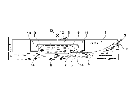
Fig. 1 shows a device for picking up particles from the surface of a water
system. A hull body
1 is moved over a surface 2 of a water system to clean the surface 2 of the
water system. As
the hull body 1 moves over the surface 2 of water system, waves are calmed by
means of a
bow section 3 of the hull body 1. Particles of dirt floating on the surface 2
of the water system
are displaced by the movement of the hull body 1 over the surface 2 of the
water system into a
flow which flows along a lower surface 4 of the hull body 1. The flow with the
dirt particles
flows beneath the hull body 1 into an inflow area 5, where an inflow or inlet
opening 7 is
formed next to a separation blade 6, so that water containing particles then
passes through this
inlet opening into a particle separation space 8. Downstream from the inlet or
inflow opening
7, an eddy current is formed, so that the dirt particles float to the top in
the particle separation
space 8, i.e., to the surface of the water. A second eddy develops above the
outlet opening of
the particle separation space 8. Special form elements 14 serve to stabilize
the eddies in the
particle separation space 8. In this way, a pulsation of the eddies, for
example, can be mini-
mized or even entirely prevented.
A separation of the particles to be separated from the particle separation
space takes place in
particle-collecting spaces 10, 11, which are arranged next to one another and
in which the
particles are concentrated, the separation being accomplished by means of
embankment ele-
ments or ramp elements 9, which belong to a separation mechanism for
separating the parti-
cles. The separation method used corresponds to the principle of hydrodynamic
separation.
During operation of the device shown in Figure 1 for picking up particles from
the surface 2
of the water system, a closed space 12 is formed, including the particle
separation space 8 and
the particle-collecting spaces 10, 11 and is hermetically sealed with respect
to the environ-
ment in the embodiment shown here, in particular by means of an airtight
design. With the
CA 02742691 2011-05-03
-7-
help of a pressure-regulating device 13, an internal pressure in the closed
space 12 is adjusted
to thereby establish a filling level of the water that contains particles in
the particle separation
space 8 in this way so that the filling level is adjusted in relation to the
embankment or ramp
elements 9, which in turn influences the separation of the dirt particles from
the particle sepa-
ration space 8 into the particle-collecting spaces 10, 11. With the help of
the internal pressure
regulation, it is possible to respond to changes relevant to rough seas or the
draft of the ship
for the device in order to ensure optimal separation of particles in
accordance with the situa-
tion. For this purpose, an automatic water level control device and/or an
optical monitoring of
the closed space 12 may be provided. The internal pressure can be increased
and the water
level can be lowered and/or the internal pressure lowered and the water level
raised by com-
pressors.
Fig. 2 shows a perspective diagram of the device from Fig. 1 in a sectional
view. For the same
features, Fig. 2 uses the same reference numerals as those used in Fig. 1.
The features of the invention disclosed in the preceding description, the
claims and the figures
may be important either individually or in any combination for the realization
of the invention
in its different embodiments.