Language selection

Search

Patent 2742795 Summary

Third-party information liability

Some of the information on this Web page has been provided by external sources. The Government of Canada is not responsible for the accuracy, reliability or currency of the information supplied by external sources. Users wishing to rely upon this information should consult directly with the source of the information. Content provided by external sources is not subject to official languages, privacy and accessibility requirements.

Claims and Abstract availability

Any discrepancies in the text and image of the Claims and Abstract are due to differing posting times. Text of the Claims and Abstract are posted:

  • At the time the application is open to public inspection;
  • At the time of issue of the patent (grant).
(12) Patent: (11) CA 2742795
(54) English Title: EMBEDDED WIRELESS ANTENNA FOR NETWORK TV
(54) French Title: ANTENNE SANS FIL INTEGREE POUR TELEVISEUR EN RESEAU
Status: Expired and beyond the Period of Reversal
Bibliographic Data
(51) International Patent Classification (IPC):
  • H04N 05/44 (2011.01)
  • H04B 07/24 (2006.01)
(72) Inventors :
  • JING, XIANGPENG (United States of America)
  • LIU, AIXIN (United States of America)
  • NGUYEN, DJUNG (United States of America)
  • PATIL, ABHISHEK (United States of America)
(73) Owners :
  • SONY ELECTRONICS INC.
  • SONY CORPORATION
(71) Applicants :
  • SONY ELECTRONICS INC. (United States of America)
  • SONY CORPORATION (Japan)
(74) Agent: GOWLING WLG (CANADA) LLP
(74) Associate agent:
(45) Issued: 2013-12-17
(86) PCT Filing Date: 2009-10-13
(87) Open to Public Inspection: 2010-05-27
Examination requested: 2011-05-04
Availability of licence: N/A
Dedicated to the Public: N/A
(25) Language of filing: English

Patent Cooperation Treaty (PCT): Yes
(86) PCT Filing Number: PCT/US2009/060479
(87) International Publication Number: US2009060479
(85) National Entry: 2011-05-04

(30) Application Priority Data:
Application No. Country/Territory Date
12/273,771 (United States of America) 2008-11-19

Abstracts

English Abstract


A WiFi chipset (38) is integrated into a TV chassis (13) as are wireless audio-
video signal antennas (42, 46) that
feed the chipset (38). The TV processor (40) causes signals from home network
components received through the antennas (42,
46) and chipset (38) to be displayed on the TV.


French Abstract

Chipset WiFi (38) incorporé à un châssis (13) de téléviseur conjointement avec des antennes (42, 46) pour signaux audio/vidéo sans fil transmis au chipset (38). Un processeur (40) de téléviseur permet l'affichage sur le téléviseur des signaux issus de composants de réseau domestique reçus via les antennes (42, 46) et le chipset (38).

Claims

Note: Claims are shown in the official language in which they were submitted.


WHAT IS CLAIMED IS:
1. TV comprising:
a chassis;
a TV display screen on a front of the chassis;
a TV signal processing board supported on the chassis;
a wireless module on the signal processing board configured to receive at
least audio and
video signals;
a TV processor on the signal processing board and communicating with the
wireless
module, the audio-video signals being presentable on the TV display under the
control of the TV
processor;
a TV tuner receiving TV signals from a TV signal source;
one or more antenna elements inside the chassis and sending at least audio and
video
signals received from a home network to the wireless module;
a bezel surrounding the chassis, and
a display shield in the chassis and disposed between the TV display and the
signal
processing board, the display shield defining an outer periphery, the one or
more antenna
elements being juxtaposed with the bezel beyond the outer periphery of the
display shield.
2. The TV of Claim 1, wherein an electrical lead connecting the antenna
element to the
wireless module is disposed between the bezel and the outer periphery of the
display shield.
3. The TV of Claim 1 or 2, wherein the one or more antenna elements
comprise a first
antenna element and a second antenna element located separately.
4. The TV of Claim 3, wherein the first antenna element is disposed
parallel to a first edge
of the chassis, the second antenna element being disposed parallel to a second
edge of the
chassis, the first and second edges being substantially perpendicular to each
other.
8

5. The TV of Claim 3, wherein the signal processing board defines first
through fourth
edges respectively facing first through fourth edges of the chassis, the TV
tuner being juxtaposed
with the third and fourth edges of the signal processing board, the first and
second antenna
elements being juxtaposed with the first and second edges of the chassis.
6. Apparatus, comprising:
wireless chipset integrated into a TV chassis;
one or more wireless audio-video signal antenna elements in the chassis and
feeding the
chipset;
a TV processor in the chassis causing signals from home network components
received
through the one or more antenna elements and chipset to be displayed on the
TV; and
a TV signal processing board supported on the chassis, the chipset and TV
processor
being mounted on the signal processing board.
7. The apparatus of Claim 6, wherein the chipset is a WiFi chipset.
8. The apparatus of Claim 6 or 7, further comprising a TV tuner in the
chassis receiving TV
signals from a source of TV signals.
9. The apparatus of any one of Claim 6-8, compressing a bezel surrounding
the chassis and
a display shield in the chassis and disposed between a TV display screen and
the signal
processing board, the display shield defining an outer periphery, the antenna
element being
juxtaposed with the bezel beyond the outer periphery of the display shield .
10. The apparatus of any one of Claims 6-10, wherein an electrical lead
connecting the
antenna element to the chipset is juxtaposed with the bezel beyond the outer
periphery of the
display shield.
11. The apparatus of Claims 6-11, wherein the one or more antenna elements
comprise a first
antenna element and a second antenna element.
9

12. The apparatus of Claim 11, wherein the first antenna element is
disposed parallel to a
first edge of the chassis, the second antenna element being disposed parallel
to a second edge of
the chassis, the first and second edges being substantially perpendicular to
each other.
13. The apparatus of Claim 11, wherein the signal processing board defines
first through
fourth edges respectively facing first through fourth edges of the chassis, a
TV tuner being
juxtaposed with the third and fourth edges of the signal processing board, the
first and second
antenna elements being juxtaposed with the first and second edges of the
chassis.
14. System for facilitating presentation on a TV in a home network audio-
video content
wirelessly received from the home network without requiring antenna wires
extending outside
the TV to receive the content, comprising:
means for displaying video content, the means for displaying including a TV
display
screen;
means for holding the means for displaying, the means for holding including a
TV
chassis;
one or more antenna elements inside the means for holding and configured for
wirelessly
receiving the audio-video content from the home network;
a TV signal processing board supported on the TV chassis;
a wireless module receiving signals from the one or more antenna elements;
a TV processor communicating with the wireless module; and
a TV tuner receiving TV signals from a TV signal source.
15. The system of Claim 14, comprising a bezel surrounding the chassis and
a display shield
in the chassis and disposed between the TV display screen and the signal
processing board, the
display shield defining an outer periphery, the one or more antenna elements
being located at the
bezel and distanced from the outer periphery of the display shield.
16. The system of Claim 15, wherein an electrical lead connecting the one
or more antenna
elements to the wireless module is juxtaposed with the bezel and distanced
from the outer
periphery of the display shield.
10

17. The system of any one of Claims 14-16, wherein the one or more antenna
elements
comprise a first antenna element and a second antenna element.
18. The system of Claim 17, wherein the first antenna element is disposed
parallel to a first
edge of the chassis, the second antenna element being disposed parallel to a
second edge of the
chassis, the first and second edges being substantially perpendicular to each
other.
19. The system of Claim 17, wherein the signal processing board defines
first through fourth
edges respectively facing first through fourth edges of the chassis, the TV
tuner being juxtaposed
with the third and fourth edges of the signal processing board, the first and
second antenna
elements being juxtaposed with the first and second edges of the chassis.
20. Apparatus, comprising:
wireless chipset integrated into a TV chassis;
one or more wireless audio-video signal antenna elements in the chassis and
feeding the
chipset;
a TV processor in the chassis causing signals from home network components
received
through the one or more antenna elements and chipset to be displayed on the
TV;
a bezel surrounding the chassis and a display shield in the chassis, the one
or more
antenna elements being juxtaposed with the bezel beyond the outer periphery of
the display
shield.
21. The apparatus of Claim 20, wherein the chipset is a WiFi chipset.
22. The apparatus of Claim 20 or 21, further comprising a TV tuner in the
chassis receiving
TV signals from a source of TV signals.
23. The apparatus of any one of Claims 20-22, further comprising a TV
signal processor
supported on the chassis, the chipset and TV processor being mounted on the
signal processing
board.
11

24. The apparatus of Claim 23, wherein the bezel is disposed between a TV
display screen
and the signal processing board.
25. The apparatus of any one of Claims 20-24, wherein an electrical lead
connecting the
antenna element to the chipset is juxtaposed with the bezel beyond the outer
periphery of the
display shield.
26. The apparatus of any one of Claims 20-25, wherein the one or more
antenna elements
comprise a first antenna element and a second antenna element.
27. The apparatus of Claim 26, wherein the first antenna element is
disposed parallel to a first
edge of the chassis, the second antenna element being disposed parallel to a
second edge of the
chassis, the first and second edges being substantially perpendicular to each
other.
28. The apparatus of Claim 26, wherein the signal processing board defines
first through
fourth edges respectively facing first through fourth edges of the chassis, a
TV tuner being
juxtaposed with the third and fourth edges of the signal processing board, the
first and second
antenna elements being juxtaposed with the first and second edges of the
chassis.
12

Description

Note: Descriptions are shown in the official language in which they were submitted.


CA 02742795 2011-05-04
WO 2010/059313 PCT/US2009/060479
EMBEDDED WIRELESS ANTENNA FOR NETWORK TV
1. FIELD OF THE INVENTION
The present invention relates generally to embedded wireless modules
(chipsets) and
associated antennas for network TVs.
II. BACKGROUND OF THE INVENTION
Home networks are provided in which inform-nation including multimedia is
shared
among networked components. For example, a TV might access a disk player or
central
server to play multimedia programming stored on disk or at the server. The TV
might also
access a hard disk drive to play recorded TV programming, display digital
photographs, etc.
TVs also evolve, and presently relatively large flat panel display TVs can be
mounted
on walls as beautiful pieces of art work in which unsightly wires (network
cables, video
cables, etc.) are removed from view. This is often accomplished using wireless
technology,
wherein TVs wirelessly receive multimedia information from other components in
the
network.
As understood herein, relatively large wireless bandwidth is required to
transfer
multimedia information in a home network. For instance, compressed high
definition (HID)
video requires between twenty and fifty megabits per second of bandwidth.
As also understood herein, current wireless adapters for TVs such as universal
serial
bus (USB) adapters typically require the host CPU to process the wireless
protocol, which
greatly lowers both the TV and wireless performance, due to the limited
processing capability
of the TV CPU and its high application load. Although some USB adapters
offload the
wireless processing, the USB driver that must be executed by the TV processor
still
consumes a great amount of processing capacity in the TV. Still further, such
adapters often

CA 02742795 2011-05-04
WO 2010/059313 PCT/US2009/060479
result in poor reception because the adapter must be plugged in behind the TV,
reducing
received wireless signal strength. Furthermore, the customer must install the
electrical
connections behind the TV and mount the antennas on the TV, which is not only
inconvenient but which also may result in unsightly appearance as well as poor
wireless
performance.
SUMMARY OF THE INVENTION
Accordingly, a TV includes a chassis, a TV display on the chassis, and a TV
signal
processing board supported on the chassis. A wireless module is on the signal
processing
board and likewise a TV processor is on the signal processing board in
communication with
the wireless module using, e.g., standard communication buses. Network
applications in the
TV can stream audio and video as well as transfer data using the wireless
module from a
home network or the Internet. Additionally, a TV tuner receives TV signals
from a TV signal
source. As set forth further below, at least one antenna element is inside the
chassis and
sends the audio-video signals, which are received from a home network, to the
wireless
module, as well as, if desired, sending audio andfor video and/or non-
audio/video data back
to the network. The wireless module and antenna can be configured for, e.g.,
Wihi,.
Bluetooth, etc.
In example embodiments a bezel surrounds the chassis and a display shield is
in the
chassis and is disposed between the TV display and the signal processing
board. The display
shield defines an outer periphery, and the antenna element is juxtaposed with
the bezel
beyond the outer periphery of the display shield. In some implementations an.
electrical lead
connecting the antenna element to the wireless module is also juxtaposed with
the bezel
beyond the outer periphery of the display shield.
2

CA 02742795 2011-05-04
WO 2010/059313 PCT/US2009/060479
In example implementations at least first and second antenna elements are
provided,
with the first antenna element being disposed parallel to a first edge of the
chassis and the
second antenna element being disposed parallel to a second, perpendicular edge
of the
chassis.
In example embodiments the signal processing board defines first through
fourth
edges respectively facing first through fourth à dges of the chassis. The TV
tuner can be
juxtaposed with the third and fourth edges of the signal processing board and
the antenna
elements can be juxtaposed with the first and second edges of the chassis,
i.e., opposite the
tuner relative to the signal processing board.
In another aspect, an apparatus has a wireless chipset integrated into a TV
chassis. At
least one wireless antenna element is in the chassis for feeding the chipset.
A TV processor
in the chassis causes signals froni home network components received through
the antenna
and chipset to be displayed on the TV.
In another aspect, a system is disclosed for facilitating presentation, on a
TV in a
home network, audio-video content wirelessly received from the home network
without
requiring antenna wires extending outside the TV to receive the content. The
system includes
means for displaying video content and means for holding the means for
displaying. Antenna
means are inside the means for holding and are configured for wirelessly
receiving the audio-
video content from the home network.
The details of the present invention, both as to its structure and operation,
can best be
understood in reference to the accompanying drawings, in which like reference
numerals
refer to like parts, and in which;
3

CA 02742795 2011-05-04
WO 2010/059313 PCT/US2009/060479
BRIEF DESCRIPTION OF THE DRAWINGS
Figure 1 is a perspective view of the front of a wail-mounted flat panel TV,
showing
network components schematically; and
Figure 2 is a rear elevation view of the rear of an example embodiment of the
TV with
the outer skin removed to expose internal components.
DETAILED DESCRIPTION OF THE PREFERRED EMBODIMENT
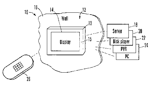
Referring initially to Figure 1, a home network 10 may include one more TVs 12
(only a single TV shown) with a TV chassis 13 holding a TV display 14.
Typically, a plastic
frame-like bezel 15 frames the display 14.
A TV 12 may be mounted by means known. in the art on a surface 16 of a
dwelling,
such as a wall or ceiling. The TV 12 may be an analog and/or digital TV with a
flat panel
(matrix-type) standard definition and/or high definition (HD) display 14,
although other types
of displays may be used.
The network. 10 may include various components that communicate audio-video
information wirelessly to the TV 12 using, e.g., WiFi principles, Bluetooth
principles, or
other wireless principles known in the art. For example, the TV 12 may receive
compressed
or uncompressed HD video from a computer server 18, a disk player 20, a
personal video
recorder (PVR) 22, and a personal computer (PC) 24, as well as other
information such as
digital photographs for display on the TV 12. Other network components such as
game
players or indeed other TVs may be provided in the network 10. A hand-held
remote control
device 26 may be manipulated by a person to input wireless command signals to
the TV 12
and/or to various network components in accordance with principles known in
the art.
Now referring to Figure 2, the rear of an example embodiment of the TV 12
(with any
outer skin or covering removed) is shown. A metal display shield 28 such as a
liquid crystal
4

CA 02742795 2011-05-04
WO 2010/059313 PCT/US2009/060479
display (LCD) shield typically is registered with the display 14 to be
generally flush
therewith, to shield the display elements of the display 14 from interference
that might be
generated by the components on the opposite side of the shield 28 from the
display 14. As
divulged in more detail below, it is desirable that the antennas are disposed
away from the
metal display shield for improved reception.
Among the shielded components alluded to above can be a TV power module 30 for
powering the TV and a TV signal processing board 32 for holding sub-
components. Both the
TV power module 30 and 'I'V signal processing board 32 typically are mounted
to the shield
28. A display power inverter 34 may also be mounted on the shield 28 for
purposes known in
the art of, e,g., LCD displays.
The TV signal processing board 32 may hold, among other things, a TV tuner 36
and
a wireless module 38 such as but not limited to an 802.11 ar`b,'g,'n chipset
made by Broadcom,
Marvell, Atheros, or Ralink with a peripheral component interconnect (PC`I) or
PCI express
forn.-i factor (e.g., Ralink 2880) and which consequently may communicate with
a TV
processor 40 on the signal processing board over a mini PCI bus or PCI express
bus or other
appropriate communication buses. Also, the wireless module 38 may further
include a
Bluetooth transceiver, in which case such a combination chipset may assume a
secure digital
input/output (SDIO) form factor and communicate with the TV processor 40 over
an SDIO
bus or a USB bus. To reduce the processing load on the TV (host) processor,
wireless
modules that have the capability to offload processing onto the wireless
chipset are preferred.
Such processing offloading chipsets place very little load on the host
processor.
As shown in Figure 2, one or more wireless antenna elements may be included
within
the TV 1.2. For example, a first elongated antenna element 42 may be disposed
near a top
edge 44 of the TV 12 and parallel thereto (i.e., horizontally), while a second
elongated
antenna element 46 may be disposed near a left edge 48 (or right edge) of the
TV 12 and

CA 02742795 2011-05-04
WO 2010/059313 PCT/US2009/060479
parallel thereto (i.e., vertically). In the example embodiment shown, the
antenna elements
42, 46 are disposed between the edges of the display shield 28 and the plastic
bezel 15 that
frames the TV, and may be co-planar with the bezel as shown. Furthermore, in
the example
shown when the tuner 36 is mounted near one set of edges of the signal
processing board 32,
in this case, near the right and bottom edges, the antenna elements 42, 46 are
mounted near
opposite counterpart edges the TV 12, in this case, near the top and left
edges of the TV 12.
The antenna elements 42, 46 may be dual-band multiple input-multiple output
(MIMO) antenna elements that are configured for reception of 2.4GUz signals
and, 5GHz
signals. Furthermore, as can be appreciated from the dashed line 50,
connecting wires from
the antenna elements 42, 46 (only the line from the first antenna 46 shown) to
the wireless
module 38 may be routed in the space between the outer edges of the shield 28
and the bezel
15. To reduce the radiofrequency signal loss of antenna extension cables, a
bus extension
cable (when using USB) can be used to extend the wireless module closer to the
antenna,
With the above in mind, the present invention recognizes that a MIMO antenna
may
be implemented in separate antenna elements, and it can be advantageous to
separate the
locations of those elements for diversity gain (a benefit of 802.1 in using
MIMO technology).
The antenna element placement and positioning shown in figure 2 can produce
optimal
reception and diversity and minimize interference to the TV tuner 36. Also,
mounting the
antenna elements inside the plastic bezels at the edge and outside the metal
shield can
produce improved reception, it being understood that the exact antenna
positions can be
determined based on different TV model configurations. The lines 50 connecting
the antenna
elements to the wireless module may be mini coaxial cables (with Hirose U.FL
type
connectors) to minimize signal loss and they can be wired along the edge of
the TV inside the
bezels as shown to promote network performance.
6

CA 02742795 2011-05-04
WO 2010/059313 PCT/US2009/060479
In non-limiting implementations a SDIO controller may be included, e.g., on
the
signal processing board 32 to allow the TV 12 to access a secure digital media
card (not
shown) to display photos or other media. Without limitation, the wireless
module 38 may be
implemented by a USB WiFi with the capability to offload certain CPU
functions. For
example, a Broadcor 4323 chip may be used.
Completing the description of Figure 2, in addition to communicating audio,
video,
and data with the home network through the antennas 42, 46 and wireless module
38, the TV
12 receives, through the TV tuner 36, TV signals from a source 52 of TV
programming such
as a set-top box, a cable TV source, a satellite TV receiver, a conventional
terrestrial TV
broadcast antenna, etc.
While the particular EMBEDDED WIRELESS ANTENNA FOR NETWORK TV is
herein shown and described in detail, it is to be understood that the subject
matter which is
encompassed by the present invention is limited only by the claims.
7

Representative Drawing
A single figure which represents the drawing illustrating the invention.
Administrative Status

2024-08-01:As part of the Next Generation Patents (NGP) transition, the Canadian Patents Database (CPD) now contains a more detailed Event History, which replicates the Event Log of our new back-office solution.

Please note that "Inactive:" events refers to events no longer in use in our new back-office solution.

For a clearer understanding of the status of the application/patent presented on this page, the site Disclaimer , as well as the definitions for Patent , Event History , Maintenance Fee  and Payment History  should be consulted.

Event History

Description Date
Inactive: IPC expired 2018-01-01
Time Limit for Reversal Expired 2016-10-13
Letter Sent 2015-10-13
Grant by Issuance 2013-12-17
Inactive: Cover page published 2013-12-16
Inactive: Final fee received 2013-10-02
Pre-grant 2013-10-02
Notice of Allowance is Issued 2013-08-16
Letter Sent 2013-08-16
Notice of Allowance is Issued 2013-08-16
Inactive: Approved for allowance (AFA) 2013-08-07
Amendment Received - Voluntary Amendment 2013-03-13
Inactive: S.30(2) Rules - Examiner requisition 2012-11-15
Inactive: Cover page published 2011-07-11
Letter Sent 2011-06-29
Inactive: Acknowledgment of national entry - RFE 2011-06-29
Inactive: IPC assigned 2011-06-27
Application Received - PCT 2011-06-27
Inactive: First IPC assigned 2011-06-27
Inactive: IPC assigned 2011-06-27
National Entry Requirements Determined Compliant 2011-05-04
Request for Examination Requirements Determined Compliant 2011-05-04
All Requirements for Examination Determined Compliant 2011-05-04
Application Published (Open to Public Inspection) 2010-05-27

Abandonment History

There is no abandonment history.

Maintenance Fee

The last payment was received on 2013-09-20

Note : If the full payment has not been received on or before the date indicated, a further fee may be required which may be one of the following

  • the reinstatement fee;
  • the late payment fee; or
  • additional fee to reverse deemed expiry.

Patent fees are adjusted on the 1st of January every year. The amounts above are the current amounts if received by December 31 of the current year.
Please refer to the CIPO Patent Fees web page to see all current fee amounts.

Fee History

Fee Type Anniversary Year Due Date Paid Date
Request for examination - standard 2011-05-04
Basic national fee - standard 2011-05-04
MF (application, 2nd anniv.) - standard 02 2011-10-13 2011-09-23
MF (application, 3rd anniv.) - standard 03 2012-10-15 2012-09-25
MF (application, 4th anniv.) - standard 04 2013-10-15 2013-09-20
Final fee - standard 2013-10-02
MF (patent, 5th anniv.) - standard 2014-10-14 2014-10-06
Owners on Record

Note: Records showing the ownership history in alphabetical order.

Current Owners on Record
SONY ELECTRONICS INC.
SONY CORPORATION
Past Owners on Record
ABHISHEK PATIL
AIXIN LIU
DJUNG NGUYEN
XIANGPENG JING
Past Owners that do not appear in the "Owners on Record" listing will appear in other documentation within the application.
Documents

To view selected files, please enter reCAPTCHA code :


To view images, click a link in the Document Description column. To download the documents, select one or more checkboxes in the first column and then click the "Download Selected in PDF format (Zip Archive)" or the "Download Selected as Single PDF" button.

List of published and non-published patent-specific documents on the CPD .

If you have any difficulty accessing content, you can call the Client Service Centre at 1-866-997-1936 or send them an e-mail at CIPO Client Service Centre.


Document
Description 
Date
(yyyy-mm-dd) 
Number of pages   Size of Image (KB) 
Claims 2011-05-03 5 240
Abstract 2011-05-03 1 65
Description 2011-05-03 7 435
Drawings 2011-05-03 1 33
Representative drawing 2011-06-29 1 13
Claims 2013-03-12 5 192
Representative drawing 2013-11-19 1 12
Acknowledgement of Request for Examination 2011-06-28 1 178
Reminder of maintenance fee due 2011-06-28 1 114
Notice of National Entry 2011-06-28 1 204
Commissioner's Notice - Application Found Allowable 2013-08-15 1 163
Maintenance Fee Notice 2015-11-23 1 170
PCT 2011-05-03 9 371
Correspondence 2013-10-01 2 52