Note: Descriptions are shown in the official language in which they were submitted.
WO 2010/056429 CA 02742827 2011-05-05
PCT/US2009/059322
SYSTEM FOR CLOSED-LOOP CONTROL OF
COMBUSTION IN ENGINES
BACKGROUND
[0001] The invention relates generally to combustion engines, and more
particularly, to a system for closed-loop control of combustion in engines,
for
example, gas engines.
[0002] In an engine, for example gas engine, a mixture of gaseous fuel
and air
are compressed within each of the engine cylinders to create an air-fuel
mixture that
ignites due to the heat and pressure of compression (self or auto ignition
relates to
diesel engine) or an ignition source, for example spark plug in gas engines.
The air-
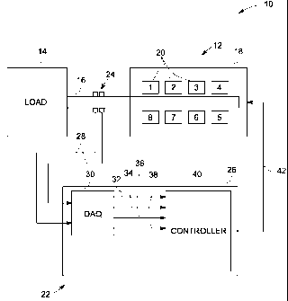
fuel mixture is exploded via the use of an ignition plug to generate an output
power.
Unfortunately, engine efficiency, power output, fuel consumption, exhaust
emissions,
and other operational characteristics are less than ideal. In addition,
conventional
techniques to improve one operational characteristic often worsen one or more
other
operational characteristic. For example, attempts to decrease specific fuel
consumption often cause increases in various exhaust emissions. Vehicle
exhaust
emissions include pollutants such as carbon monoxide (CO), nitrogen oxides
(N0x),
sulfur oxides (S0x), particulate matter (PM), and smoke generated due to
incomplete
combustion of fuel within the combustion chamber. The amount of these
pollutants
varies depending on the fuel-air mixture, compression ratio, injection timing,
ambient
conditions, engine output power, and so forth.
[0003] Engine performance may be improved by controlling combustion
within each of the engine cylinders. The factors affecting engine performance
may
include reduction in coefficient of variance between different cylinders,
operating
engine closer to knock limits, improved ignition control, changes in gas
quality,
misfired cylinder, or the like. One or more parameters related to the engine
would
need to be monitored to control the combustion within each cylinder of the
engine.
Conventionally, piezoelectric pressure transducers, ion current sensors, or
optical
detectors are used to monitor one or more parameters related to the engine.
However,
1
WO 2010/056429 CA 02742827 2011-05-05 PCT/US2009/059322
these conventional sensors are inaccurate, lack in reliability, and are
expensive to be
used. Another issue with the conventional approach is the requirement of large
number of sensors. Hence the complexity of the control system is also
increased.
Also, none of the conventional approaches provide a feedback of an engine
power
output to a control system.
[0004] There is a need for a suitable control unit that can reliably
detect one or
more combustion parameters related to an engine and control combustion within
each
cylinder of the engine so as to improve engine performance.
BRIEF DESCRIPTION
[0005] In accordance with an exemplary embodiment of the present
invention,
a combustion control system for a combustion engine system is disclosed. The
combustion control system includes a magnetic torque sensor disposed between
an
engine and a load. The magnetic torque sensor is configured to directly
measure
engine torque and output a torque signal indicative of the engine torque. A
control
unit is communicatively coupled to the magnetic torque sensor. The control
unit is
configured to receive the torque signal and determine one or more combustion
parameters based on the torque signal. The control unit is also configured to
control
one or more manipulating parameters of the engine based on the one or more
combustion parameters so as to control combustion in the engine.
[0006] In accordance with another exemplary embodiment of the present
invention, a combustion engine system is disclosed.
DRAWINGS
[0007] These and other features, aspects, and advantages of the present
invention will become better understood when the following detailed
description is
read with reference to the accompanying drawings in which like characters
represent
like parts throughout the drawings, wherein:
2
WO 2010/056429 CA 02742827 2011-05-05 PCT/US2009/059322
[0008] FIG. 1 is a diagrammatical view of a combustion engine system for
example, gas engine system having a combustion control system in accordance
with
an exemplary embodiment of the present invention;
[0009] FIG. 2 is a diagrammatical view of a combustion engine system
having
a combustion control system comprising a data acquisition unit and a
controller in
accordance with an exemplary embodiment of the present invention;
[0010] FIG. 3 is a diagrammatical view of an arrangement for partial
magnetic
encoding of a shaft, in order to detect shaft torque in accordance with an
exemplary
embodiment of the present invention;
[0011] FIG. 4 is a diagrammatical view of a magnetostrictive sensor having
a
plurality of sensor coils disposed within a metallic tube in accordance with
an
exemplary embodiment of the present invention;
[0012] FIG. 5 is a diagrammatical view of a magnetostrictive sensor
configured to provide partial encoding of a shaft and detect shaft torque in
accordance
with an exemplary embodiment of the present invention; and
[0013] FIG. 6 is a diagrammatical view of a magnetoelastic torque sensor
configured to detect shaft torque in accordance with an exemplary embodiment
of the
present invention.
DETAILED DESCRIPTION
[0014] As discussed in detail below, embodiments of the present invention
provide a combustion control system for a combustion engine system. The
combustion control system includes a magnetic torque sensor disposed between
an
engine and a load. The magnetic torque sensor is configured to directly
measure
engine torque and output a torque signal indicative of the engine torque. A
control
unit is communicatively coupled to the magnetic torque sensor. The control
unit is
configured to receive the torque signal and determine one or more combustion
parameters based on the torque signal. The control unit is configured to
further
control one or more manipulating parameters of the engine based on the one or
more
3
WO 2010/056429 CA 02742827 2011-05-05 PCT/US2009/059322
combustion parameters so as to control combustion in the engine. In certain
embodiments, a contact less magnetic torque sensor is disposed around a
crankshaft
between the engine and the load. The magnetic torque sensor may be a
magnetoelastic torque sensor or a magnetostrictive torque sensor. The control
system
is used for individual cylinder diagnostics and closed loop control of
combustion in
large reciprocating engines. A single sensor is used to achieve high time
resolution
signals from the combustion event in each engine cylinder. The sensor provides
torque signal as a function of time, which can be used to analyze pressure
rise during
combustion event, for gaining information on the combustion process including
timing, intensity, stability, or the like. This information can then be used
to calculate
optimum values for manipulating variables including throttle valve position,
boost
pressure, air-fuel ratio, ignition timing, fuel injection timing, fuel amount,
valve
timing, or the like. The control system provides a reliable closed-loop
control of
combustion within each cylinder of the engine.
[0015] Referring to FIG. 1, a combustion engine system 10 in accordance
with
an exemplary embodiment of the present invention is illustrated. The system 10
includes an engine 12 coupled to a load 14 via a crankshaft 16. In one
embodiment,
the engine 12 is a gas engine. In other embodiments, the engine 12 may be an
Otto
engine or other stationary engines. The engine 12 includes a cylinder block 18
having
a plurality of engine cylinders 20. Even though 8 engine cylinders 20 are
illustrated,
the number of cylinders may vary in other embodiments depending on the
application.
The load 14 may include a generator, mechanical drive unit, or the like. The
system
also includes a combustion control system 22 configured to control combustion
within each cylinder 20 of the engine 12.
[0016] The system 22 includes a magnetic torque sensor 24 and a control
unit
26. The magnetic torque sensor 24 is disposed between the engine 12 and the
load 14.
In the illustrated embodiment, the magnetic torque sensor 24 is disposed
around the
crankshaft 16. The magnetic torque sensor is 24 is configured to directly
measure
engine torque and output a torque signal 28 indicative of the engine torque.
The
magnetic torque sensor 24 may be a magnetoelastic sensor or a magnetostrictive
sensor. The control unit 26 is communicatively coupled to the magnetic torque
sensor
4
WO 2010/056429 CA 02742827 2011-05-05 PCT/US2009/059322
24. The control unit 26 is configured to receive the torque signal 28 and
determine
one or more combustion parameters based on the torque signal and further
controls
one or more manipulating parameters of the engine 12 based on the one or more
combustion parameters so as to control combustion within each cylinder 20 of
the
engine 12. Furthermore, the torque signal 28 can be either used to monitor
engine
power output or manipulate engine parameters for an accurate control of the
power
output. In conventional systems, engine parameters are manipulated accordingly
to
control a power output. However, in such systems there is no validation done
to
check whether the power output is near to a set point.
[0017] In one embodiment, the control unit 26 includes a data acquisition
unit
(DAQ) 30 configured to receive the torque signal 28 and output a plurality of
signals
32, 34, 36, 38 corresponding to a plurality of combustion parameters based on
the
torque signal 28. In the illustrated embodiment, the signals 32, 34, 36, and
38
correspond to engine cylinder knock, misfired cylinder, combustion timing;
torque
oscillations, or combinations thereof The control unit 26 also includes a
controller 40
configured to receive the signals 32, 34, 36, 38 corresponding to the
plurality of
combustion parameters and output one or more signals 42 so as to control one
or more
manipulating parameters for controlling combustion within each cylinder 20 of
the
engine 12. In some embodiments, the controller 40 may additionally receive
input
signals corresponding to engine speed, power, and emission levels for
controlling
combustion within the engine 12. The manipulating parameters may include a
throttle
valve position, boost pressure, air-fuel ratio, fuel ignition timing, fuel
injection timing,
fuel amount; exhaust gas recirculation, or combinations thereof. One or more
corresponding control devices of the engine 12 may be controlled so as to
control the
manipulating parameters described herein.
[0018] Referring to FIG. 2, a combustion engine system 10 in accordance
with
an exemplary embodiment of the present invention is illustrated. As discussed
previously, the system 10 includes the engine 12 coupled to the load 14 via
the
crankshaft 16. The system 10 also includes the combustion control system 22
configured to control combustion within each cylinder 20 of the engine 12. The
magnetic torque sensor 24 is disposed between the engine 12 and the load 14.
The
5
WO 2010/056429 CA 02742827 2011-05-05 PCT/US2009/059322
system 22 includes the control unit 26 communicatively coupled to the magnetic
torque sensor 24. The control unit 26 is configured to receive the torque
signal 28 and
determine one or more combustion parameters based on the torque signal and
further
control one or more manipulating parameters of the engine 12 based on the one
or
more combustion parameters so as to control combustion within each cylinder 20
of
the engine 12.
[0019] In the illustrated embodiment, the data acquisition unit (DAQ) 30
of
the control unit 26 includes a signal conditioning unit 44, a high pass filter
46, torque
slope estimator 48, and a heat release estimator 50. The signal conditioning
unit 44
receives the torque signal 28 and outputs a time-resolved conditioned torque
signal 52
suitable for estimating the combustion parameters. The high pass knock filter
46 is
configured to receive the conditioned torque signal 52 and provide a cylinder
knock
signal 34 in kilohertz (kHz) based on the conditioned signal 52. The torque
slope
estimator 48 is configured to receive the conditioned torque signal 52 and
provide a
misfired cylinder signal 32. The heat release estimator 50 is configured to
receive the
conditioned torque signal 52 and provide a combustion timing signal 36. It
should be
noted herein that the architecture of the illustrated data acquisition unit 30
is an
exemplary embodiment and should not be construed in any way as limiting the
scope.
The controller 40 is configured to receive the signals 32, 34, 36 and output
one or
more signals 42 so as to control one or more manipulating parameters for
controlling
combustion within each cylinder 20 of the engine 12.
[0020] In the embodiments discussed herein, only a single torque sensor is
used to obtain real-time measured information related to combustion in each
cylinder
20. In other words, combustion parameters can be detected for each cylinder
individually with high time resolution (for example, 20 kHz) by using only one
magnetic torque sensor. The magnetic sensor system 24 does not contact any
rotating
components of the engine and is designed to deliver high quality torque output
signals
without extensive signal processing. The control system 22 individually
controls gas
exchange, ignition and combustion in each cylinder 20. As a result,
coefficient of
variance is reduced, and the engine is operated closer to knock limit. The
control
system 22 facilitates improved transient behavior of the engine with changes
in gas
6
WO 2010/056429 CA 02742827 2011-05-05PCT/US2009/059322
quality, air-fuel mixture homogeneity, igniter performance, and load
conditions such
as mechanical drive, mini grid, or the like.
[0021] In the discussed embodiments, cylinder-to-cylinder variability
(variation in cylinder parameters) is detected with high time resolution by
using only
one magnetic torque sensor. Cylinder-to-cylinder variability may be in terms
of
power, air-fuel ratio, or the like. In one embodiments, cylinder-to-cylinder
deviation
and coefficient of variance are reduced with improve gas exchange and
turbocharger
performance by individually controlling fuel injection in each cylinder 20.
[0022] Referring to FIG. 3, a magnetic encoding tool 53 for creating a
magnetostrictive torque sensor is illustrated disposed around the crankshaft
16.
Magnetostrictive measurement methods make use of the phenomenon that material
changes dimensions upon being magnetized. The accuracy of magnetostrictive
measurement systems can be improved by combining the magnetostrictive effect
with
a magnetic encoding of the shaft 16 or the encoding section applied to the
shaft 16. In
such sensor designs, the alignment of the magnetic domains in the
ferromagnetic
material imparts some change in the material dimensions along a magnetic axis.
The
inverse effect is the change of magnetization of a ferromagnetic material due
to
mechanical stress. The magnetic encoding essentially converts the shaft 16
into a
component of the sensing system. When a mechanical torque is applied to the
shaft
16, a torque-dependent magnetic field is measurable close to the encoded
region of
the shaft 16.
[0023] In the illustrated embodiment, enhanced encoding systems for shafts
and measuring properties thereof is achieved by sectional encoding where
encoded
zones or magnetic channels are generated in axial or circumferential
directions of the
shaft 16. For large diameter shafts, it is beneficial to employ this magnetic
encoding
where relevant flux densities can be achieved with lower encoding currents.
[0024] The shaft 16 can be a ferromagnetic material or may have at least a
section of ferromagnetic material affixed to the shaft 16. In the illustrated
embodiment, two arc segments 54, 56 are disposed about a segment of the shaft
16.
7
WO 2010/056429 CA 02742827 2011-05-05 PCT/US2009/059322
One conducting arc segment 54 is coupled to a positive polarity encoding
source (not
shown) via a positive end 58 such that the encoding currents travel along from
the
positive end and along the arc segment 54. In this embodiment, another end of
the
conducting arc segment 54 is coupled to the shaft 16 via an electrode 725. The
encoding current pulse travels along the arc segment 54 and the return current
travels
along the shaft 16 to a return electrode via a return end 60 that is
electrically coupled
to the encoding source (not shown).
[0025] The other conducting arc segment 56 is coupled via a return end 62
to
the encoding source (not shown). The encoding signals travel from the encoding
source (not shown) to the positive end 64 via an electrode in contact with the
shaft 16,
then along the surface of the shaft 16 and through an electrode 66. The
encoding
currents travel along the arc segment 56 and return via the return end 62 to
the
encoding source (not shown). Once again, this encoding generates sectional
magnetic
regions about the circumference of the shaft 16. The combination of the pair
of
conducting arc segments 54, 56 that create the polarized magnetic regions also
creates
the domain boundary 68 therebetween. In this embodiment, there are two
polarized
regions orientated along an axial direction of the shaft 16. The magnetic
field
measurement is simpler since the shaft 16 rotates and there is a greater
length of
sensing area in the circumferential direction. It should be readily apparent
that while
depicted as an arc segment of about a semi-circle, the arc segments can be a
small
portion of the shaft 16 or larger portions of the circular circumference.
Furthermore,
while shown as being circumferential, the encoded channels can be along any
direction of the shaft 16 such as axially or diagonally. An advantage of the
circumferential encoding method as shown in Fig. 3 is that the magnetic
measurement
is not affected as the shaft rotates (magnetic field output not dependent on
the
rotational position of the shaft in the encoded section). This provides torque
output
signals with high time resolution.
[0026] In one embodiment, electrical currents travel through the shaft 16
such
that magnetized regions are generated on the shaft 16. One of the features of
this
encoding system is the ability to magnetically encode channels or magnetic
polarization regions in the shaft 16. The current penetration, namely the
depth of the
8
231472 CA 02742827 2012-07-19
current density in the shaft, is controlled by the duration of the current
pulse in one
embodiment. According to a simple encoding approach, a magnetized section is
encoded one circuit at a time. To avoid that the influence of sequential
magnetization
of one section by the next magnetization, another encoding embodiment involves
applying the same current amplitude to all the conducting members and encoding
all
the sections at once.
[0027] In another embodiment, paired conducting members may be disposed
surrounding at least a portion of the shaft. The sectional magnetic encoding
takes
advantage of the asymmetrical skin effect and the fact that a current always
takes the
path of least impedance. The impedance is dominated by inductance if the
frequency
of the current is high enough. In the case of a short current pulse the return
current
flowing in the shaft will be more localized than in the case of a longer
pulse, enabling
polarized and well defined/narrow magnetic patterns. This effect is used to
magnetize
sections of a shaft with more localized channels that lead to faster changes
in the
magnetic field during sensing. In embodiments where the encoded sections are
created in axial direction or diagonally, torque signals with sufficient time
resolution
are achieved by applying multiple encoded sections and sufficiently high
nominal
speed of the shaft 16. It should be noted herein that additional details about
the
sectional magnetic encoding of the shaft can be found in U.S. Patent 7,631,564
titled
"DIRECT SHAFT POWER MEASUREMENTS FOR ROTATING MACHINERY".
[0028] Referring to FIG. 4, a magnetostrictive torque sensor 24 is illustrated
disposed around the crankshaft 16. In the illustrated embodiment, a magnetic
encoding region of the shaft 16 is illustrated by the reference numeral 76. A
plurality
of sensor coils 78 are disposed around the magnetic encoded region 76 of the
shaft 16.
The sensor coils 78 are adapted to detect a magnetic field emitted by the
encoded
region 76 of the shaft 16. This sensor design requires shielding of the
magnetic field
sensor coils 78 against external electromagnetic disturbances. In the
illustrated
embodiment, the magnetic field sensor coils 78 are positioned within a
metallic tube
80. In embodiments involving lateral movements of the shaft, multiple magnetic
field
9
WO 2010/056429 CA 02742827 2011-05-05PCT/US2009/059322
sensor coil pairs 78 must be positioned around the shaft 16. The metallic tube
80 is
used to protect the sensor coils 78 from external electromagnetic fields so as
to
improve measurement accuracy.
[0029] Referring to FIG. 5, a combustion control system 22 having a
magnetostrictive torque sensor 82 disposed around the shaft 16 is illustrated.
In the
illustrated embodiment, the magnetostrictive torque sensor design employs
total shaft
encoding and the magnetization occurs by current flowing in the axial
direction of the
shaft 16. A magnetic encoded region of the shaft 16 is indicated by the
reference
numeral 84. A first location is indicated by reference numeral 86 and
indicates one
end of the encoded region 84 and the second location is indicated by reference
numeral 88, which indicates another end of the encoded region, or the region
to be
magnetically encoded 84. Arrows 90 and 92 indicate the application of a
current
pulse. A first current pulse is applied to the shaft 16 at an outer region
adjacent or
close to the first location 86. As indicated with arrow 92, the current pulse
is
discharged from the shaft 16 close or adjacent or at the second location 88
preferably
at a plurality or locations along the end of the region 4 to be encoded. A
second
current pulse with other polarity may be applied to increase the torque sensor
performance by creating two magnetized domains in region 84 with well-defined
domain boundaries. Reference numeral 94 indicates a magnetic field sensor
element,
for example, a hall effect sensor connected to the control unit 26. The
control unit 26
may be adapted to further process a signal output by the sensor element 94 so
as to
output a signal corresponding to a torque applied to the shaft 16. The sensor
element
94 is adapted to detect a magnetic field emitted by the encoded region 84 of
the shaft
16.
[0030] If there is no stress or force applied to the shaft 16, there is no
field
detected or a constant field is detected by the sensor element 94. However, in
case a
stress or a force is applied to the shaft 16, there is a variation in the
magnetic field
emitted by the encoded region such that an increase of a magnetic field is
detected by
the sensor element 94.
10
231472 . CA 02742827 2012-07-19
[0031] In another embodiment, the current is introduced into the shaft 16 at
or
adjacent to location 88 and is discharged or taken from the shaft 16 at or
adjacent to
the location 86. In another embodiment, a plurality of current pulses may be
introduced adjacent to first location 86 and plurality of current pulses may
be
discharged adjacent to second location 88 and vice versa. In yet another
embodiment,
pinning regions (not shown) may be provided adjacent to locations 86 and 88.
These
pinning regions may be provided for avoiding a fraying of the encoded region
84.
Additional details of the illustrated embodiment can be found in U.S. Patent
7,243,557 titled "torque sensor".
[0032] Referring to FIG. 6, a magneto elastic sensor 96 disposed around the
shaft 16 is illustrated. A plurality of polarized rings 98, 100 are disposed
around the
shaft 16 such that the rings 98, 100 magnetically divide opposing polarization
regions.
In the illustrated embodiment, a domain wall 102 separates the polarized rings
98,
100. A magnetic field sensor element 104 is located proximate the rings 98,
100 and
senses the magnetic flux density. An output from the sensor element 104 are
processed such that the stresses in the rings 98, 100 correspond to the torque
imparted
upon the shaft 16. For additional details, see U.S. Patent 7,631,564.
[0033] As discussed with reference to embodiments illustrated in FIGS. 1-6, it
is reiterated that only a single magnetic torque sensor is used to achieve
real-time
measurement feedback and high time resolution signals from the combustion
event in
each engine cylinder. The control system is used for individual cylinder
diagnostics
and closed loop control of combustion in large reciprocating engines.
[0034] Only certain features of the invention have been illustrated and
described herein. It should be understood that many modifications and changes
to the
features of the present invention described herein would be obvious to those
skilled in
the art.
11