Note: Descriptions are shown in the official language in which they were submitted.
CA 02742912 2011-05-04
WO 2010/052659
PCT/1B2009/054905
1
TOOTHBRUSH AND BRISTLE AND BRUSH HEAD FOR A TOOTHBRUSH
The present invention relates to a bristle for a toothbrush, said bristle
being comprised
of a plastic monofilament, with the preferably cloverleaf-shaped bristle body
having
several longitudinal ribs arranged in star shape which project laterally from
a core
section of the bristle body. This invention relates in addition to a brush
head for an
electric toothbrush with at least one bristle tuft having at least one such
bristle and to
an electric toothbrush with such a brush head.
EP 11 13 737 B1 or US 6,871,373 B2 disclose bristles for a toothbrush which
have a
substantially cloverleaf-shaped cross-section. At the free ends the bristles
are fanned
out for some length such that the longitudinal ribs of the bristle body which
form the
cloverleaf-shaped cross-section protrude singly at the end of the bristle and
form an on
the whole flower-shaped bristle end. Such split bristle ends afford many
different
advantages including, for example, improved nestling against the tooth
surface, better
distribution of cleaning agent on the tooth surface and a high cleaning effect
on the
smooth surfaces. On the other hand, hitherto known tufts of such split
bristles are less
advantageous with regard to removing plaque or interproximal cleaning.
Above all, however, such fanned out bristle tufts are complex to manufacture.
Special
splitting machines are typically used which split open the bristles by means
of high-
speed rotary blades. This takes place in several process steps as described,
for
example, in WO 00/01276.
As explained in EP 11 13 737 B1, it was also proposed in the art to integrate
so to
speak points of preferred breaking in such cloverleaf-shaped bristles in order
to
facilitate the splitting open. During extrusion of the bristle body the
extrusion strand is
first split open into several separate strands which are then re-joined.
Suitable points
of preferred breaking result at the joints because interfaces between
corresponding
material sections are created there. As a result, the bristles break across
their full
width when split open such that the core region of the bristle body is also
split.
Based on the foregoing, it is an object of the present invention to provide an
improved
bristle and an improved bristle support, each of the type initially referred
to, as well as
an improved toothbrush, which prevent the disadvantages of the prior art while
developing the art further in advantageous manner. It is intended to provide
preferably
CA 02742912 2013-05-27
2
an easy-to-manufacture electric toothbrush which on the one hand achieves a
good nestling
of the bristle tufts against the tooth surface, a good distribution of
cleaning agent on the
tooth surface and an agreeable cleaning sensation, while on the other hand
also showing a
good cleaning performance in the removal of plague and in the removal of
stubborn dental
debris.
According to the invention this object is accomplished by a bristle; a bristle
support; and a
toothbrush described herein. Preferred embodiments of the invention are also
described
herein.
It is proposed therefore to first insert into the toothbrush unsplit bristles
with laterally
protruding longitudinal ribs and a preferably cloverleaf-shaped cross-section
and to
configure them such that they split open automatically during brushing.
According to the
invention, the bristle of the type initially referred to is of the self-
fanning type, such that the
cleaning forces acting on the bristles during normal cleaning lead to a
splitting open of the
bristle at its free end. This obviates the need to provide complex splitting
processes and
corresponding splitting machines for manufacturing the toothbrush.
Any reference to the bristle tufts can also be regarded alternatively as a
reference to a
majority of bristles in accordance with this invention, as described above and
below and in
the claims. Furthermore, other types of dental cleaning elements can be used
alternatively
instead of bristles. Also it is possible for the tufts, as described in this
connection, to be
arranged not on outer, middle and inner rings but in outer, middle or inner
regions arranged
relative to each other.
The self-fanning bristles with the laterally protruding longitudinal ribs are
grouped
advantageously in corresponding tufts with non-self-fanning bristles such that
a mixture of
fanning and non-fanning bristles exists in the corresponding tuft. This
enables a good
nestling of the bristles around the tooth surface, a good distribution of
cleaning agent and an
agreeable cleaning sensation to be combined with a high cleaning performance
with regard
to the removal of plague. Furthermore, the self-fanning can take place over
several months
in a controlled process. Also, a high density of bristles can be achieved in a
tuft and hence
on the bristle support of the brush head.
CA 02742912 2011-05-04
WO 2010/052659
PCT/1B2009/054905
3
In particularly advantageous manner, the mixed tufts comprising both fanning
bristles
with lateral longitudinal ribs and normal bristles devoid of longitudinal ribs
are arranged
in an inner area of the bristled section of the brush head while tufts
comprising non-
fanning bristles are provided on an outer edge of the bristled section, in
which
arrangement said outer tufts can have advantageously in part a greater length
and/or
height than the inner lying tufts, such that a particularly effective cleaning
of the
interproximal spaces can be achieved with said outer tufts made of non-fanning
bristles. At the same time, the fanning bristles in the inner area of the
bristled section
ensure an effective cleaning of the tooth flanks.
In an advantageous further aspect of the invention, the bristle body including
its core
section is free of points of preferred breaking, i.e., it has advantageously a
homoge-
neous material structure and microstructure over its entire cross-section.
The self-fanning construction can be achieved generally in a variety of ways.
In an
advantageous further aspect of the invention, the bristles are shaped in a
special
configuration. In particular the bristle body can be shaped such that a ratio
of an outer
diameter of an enveloping cylinder enclosing the longitudinal ribs to a
calipered
minimum outer dimension determined by placing a sliding vernier caliper
against the
bristle body lies in the range of 1.10 to 1.30, approximately. Said ratio of
the outer
diameter of the enveloping cylinder to the calipered outer dimension can vary
de-
pending on the number of longitudinal ribs. If three longitudinal ribs are
provided on
the brush body, then said ratio of the outer diameter to the calipered outer
dimension is
advantageously between 1.10 and 1.25 and in particular 1.15, approximately.
However, if four longitudinal ribs are provided on the bristle body, then said
ratio of the
outer diameter of the enveloping cylinder to said calipered outer dimension is
preferably 1.10 to 1.30 and in particular 1.20, approximately.
The bristle body may generally have a varying number of longitudinal ribs. In
an ad-
vantageous embodiment of the invention, in particular three or four
longitudinal ribs are
provided.
In addition the bristle body exhibits advantageously a certain ratio of the
depth of the
grooves between the laterally protruding longitudinal ribs to the outer
diameter of the
enveloping cylinder enclosing the longitudinal ribs. In an advantageous
further aspect
of the invention, the ratio of core diameter of an imaginary inner enveloping
cylinder
CA 02742912 2011-05-04
WO 2010/052659
PCT/1B2009/054905
4
inscribed by the grooves between the longitudinal ribs to the outer diameter
of said
enveloping cylinder enclosing the longitudinal ribs is 0.5 +/- 0.15.
Therefore, said outer
enveloping cylinder is approximately twice as large as the core diameter.
The longitudinal ribs of the brush body generally can have different
geometries. In a
particular advantageous embodiment of the invention, the cross-section of the
bristle
body is in actual fact cloverleaf-shaped and/or the longitudinal ribs have an
outer
contour which corresponds to a pitch cylinder.
Alternatively however, the longitudinal ribs can have other outer contours.
For
example, the outer contours can correspond to pitch cylinders having a
triangular
cross-section, a rectangular cross-section, a rhombic cross-section or a
hexagonal
cross-section.
Advantageously, all the longitudinal ribs have a mutually identical outer
contour in
order to achieve uniform fanning.
The previously mentioned calipered outer dimension, which can be measured by
applying a sliding vernier caliper such that the calipered minimum dimension
can be
set while the bristle is turned, can be generally between 5 and 9 mil, one mil
being
equal to 0.0254 mm. In an advantageous further aspect of the invention, said
cali-
pered dimension can be between 5.5 and 6 mil and in particular 5.75 mil,
approxi-
mately. It will be understood, of course, that the previously mentioned
calipering of the
calipered dimension using a sliding vernier caliper is only meant figuratively
in order to
illustrate the definition of the calipered dimension. Because a conventional
type of
mechanical sliding vernier caliper would be too rough for the diameter
dimensions
mentioned, a suitable high-pecision instrument such as a micrometer caliper
would
have to be used.
Said bristles with longitudinal ribs can be generally added in a varied
mixture ratio to
the non-fanned, normal bristles. Depending on the application it is possible
to use
more fanning bristles or more non-fanning bristles. A good compromise with
regard to
the removal of plaque on the one hand and to hugging the tooth surfaces and
distributing the cleaning agent on the other hand is achieved in a further
aspect of the
invention by using x = 50% +/-10% self-fanning bristles with laterally
protruding
CA 02742912 2011-05-04
WO 2010/052659
PCT/1B2009/054905
longitudinal ribs on the one hand and y = 50% +/-10% non-fanning normal
bristles on
the other hand per mixed tuft, where x + y = 100%.
Generally, the non-fanning bristles can have various cross-sectional
geometries.
Advantageously, they are devoid of longitudinal ribs, with a basic geometrical
cross-
sectional shape such as rectangular or hexagonal. The bristles provided as non-
fanning bristles are in particular bristles with a round, in particular
circular, cross-
section.
The non-fanning bristles have advantageously a diameter which is smaller than
the
previously mentioned calipered outer dimension of the self-fanning bristles
with
longitudinal ribs. For example, round bristles with a diameter of 5.5 mil can
be mixed
with self-fanning bristles with longitudinal ribs with a calipered outer
dimension of 5.75
mil.
Particularly advantageous is the use of said self-fanning bristles in a
bristled section on
which tufts of a large cross-sectional area are concentrated at the outer edge
of the
bristled section and in its central area and tufts of a small cross-sectional
area are
provided between said large-area tufts at the edge and in the center on a
middle ring
of tufts. In particular within the elongated tufts on the outer ring there are
arranged on
a middle ring several tufts having a cross-section smaller than the cross-
section of the
elongated tufts, and within these small tufts on the middle ring there is
provided at
least one tuft with a cross-section larger than the cross-section of the tufts
on the
middle ring. By virtue of this rhythmic alternation of tuft cross-sections
from inside to
outside, it is possible to achieve a high bristle density and to better
prevent a collision
of the fastening means. Furthermore, advantages also arise with regard to the
cleaning effect. Among other things, the dentifrice usually applied in the
center of the
bristled section is held better on the working surface.
Advantageously, the tufts of said middle ring and the innermost tufts are
equipped with
said self-fanning bristles.
In a further aspect of the invention, bristle tufts of various cross-sectional
shapes are
arranged on the at least one middle ring of bristles. In particular on said at
least one
middle ring bristle tufts may be provided which have an approximately square
tuft
cross-section. Alternatively or in addition, said middle ring may also include
bristle
CA 02742912 2011-05-04
WO 2010/052659
PCT/1B2009/054905
6
tufts with a round cross-section, in particular a circular cross-section. If
both angular,
in particular square, and round, in particular circular bristle tufts are
arranged on said
middle ring, they are advantageously concentrated in different sectors each.
To do
this, a variety of options exist in general. According to one advantageous
embodiment of the invention, round bristle tufts are arranged on the middle
ring in
opposing sectors, which in the non-deflected neutral position of the bristle
support
contain the toothbrush longitudinal axis. By contrast, the angular bristle
tufts of the
middle ring are advantageously arranged in opposing sectors of the bristle
support
which in the bristle support's neutral position are arranged symmetrically to
a trans-
verse axis.
In order to provide favorable space conditions for the securing of the bristle
tufts, in a
further aspect of the invention the angular bristle tufts of the middle ring,
at least some
of them, are turned at an acute angle relative to the main axes of the bristle
support
and also relative to the main axis of the annular contour of the ring on which
they are
arranged. In particular at least one of the angular bristle tufts, preferably
every sec-
ond angular bristle tuft, may have its main axis turned in such a way that the
main axis
of the bristle tuft cross-section is inclined at an acute angle to a tangent
to the middle
ring. As a result, corresponding anchor plates are turned out of the collision
range of
other anchor plates. In addition, the flexing behavior of the bristled section
can be
made more homogeneous on the whole and in particular less dependent on
direction.
Regardless of their different cross-sectional shapes, the bristle tufts of the
middle ring
have at least by approximation roughly the same area of cross-section, with
the areas
of cross-section varying in a range of preferably less than +/-25%.
Compared to the areas of cross-section of the bristle tufts of the middle
ring, the outer,
elongated bristle tufts on the outer ring as well as the at least one
innermost tuft in the
center of the bristled section have an area of cross-section at least twice as
large.
In this arrangement, on the outer ring of the bristled section there may be
arranged
advantageously several opposite lying pairs of elongated bristle tufts. For
improved
adaptation of the bristle configuration to the different cleaning tasks in
different areas
of the bristled section, said outer ring may include differently designed
pairs of
elongated bristle tufts which differ in respect of their bristle length and/or
height and/or
cross-sectional area.
CA 02742912 2011-05-04
WO 2010/052659
PCT/1B2009/054905
7
Various configurations are generally possible in this context. According to an
ad-
vantageous embodiment of the invention, opposing sectors of the bristle
support,
which in its non-deflected neutral position contain the toothbrush
longitudinal axis,
include longer bristle tufts and/or elongated bristle tufts of greater cross-
sectional area
than the tufts in sectors oriented at right angles thereto in a direction
transverse to the
toothbrush longitudinal axis.
In addition to the elongated bristle tufts, the outer ring may advantageously
provide
further bristle tufts of a not elongated contour, which advantageously may
have an
approximately round or square cross-section of a cross-sectional area smaller
than
the cross-sectional area of the elongated bristle tufts.
In an advantageous further aspect of the invention, the central area of the
bristled
section includes two equally elongated bristle tufts whose longitudinal axis,
that is, the
longitudinal dimension of the elongated cross-section, is aligned parallel to
a main
axis of the bristle support. In particular said innermost bristle tufts may
have their
longitudinal axes oriented parallel to the toothbrush longitudinal axis in the
non-
deflected neutral position of the bristle support and/or oriented towards the
elongated
bristle tufts of the outer ring which on the outer ring have the greatest
height and/or
greatest cross-sectional area.
The bristle support and/or the bristled section may generally have various
outer
contours, with the bristle support being advantageously of a round
configuration in
particular when driven rotationally. In a particularly advantageous further
aspect of
the invention however, the bristle support is not circular but of a shape
deviating from
the circular. In particular the bristle support may be of an oval or
elliptical con-
figuration or slightly flattened in a similar way. Alternatively or in
addition, at least the
outer row or the outer ring of bristle tufts may be arranged on an oval or on
an ellipse
or on a ring flattened in similar manner.
As seen looking at the top of the bristle support, the bristle tufts are
advantageously
arranged symmetrically relative to the main axes of the bristle support and/or
rota-
tionally symmetrically, in particular in such a way that the bristle tufts or
their points of
attachment on the bristle support are engageable one into the other by a turn
through
180 degrees.
CA 02742912 2011-05-04
WO 2010/052659
PCT/1B2009/054905
8
Alternatively or in addition, the bristled section may however have an
asymmetrical
contour as seen in a side view, in particular in a direction transverse to the
toothbrush
longitudinal axis, particularly in such a way that the height profile rises
more
intensively towards one side than towards the other side.
In a further aspect of the invention, the bristled section has a central
depression in the
working surface defined by the free ends of the bristle tufts, which
advantageously
may have a groove-shaped bottom curved in one direction and substantially
straight in
the direction perpendicular thereto. Through such a substantially uniaxially
curved
depression in a middle portion of the bristled section or its working surface,
it is
possible to achieve not only a better holding of the dentifrice or a similar,
gel-type
dental cleansing agent but above all a better cleaning effect on the teeth
accompanied
by a more agreeable, gentler cleaning sensation. The contour of the working
surface,
which rises to opposing circumferential sides, nestles better against the
lateral tooth
flanks which, so to speak, are enveloped in a snug fit so that in particular
the sections
of the tooth flanks adjoining the interproximal spaces are better cleaned.
Unlike bristled sections with plane depressions in the middle, it is not
necessary for
the innermost, i.e., central tufts, to bend away first. Rather, the bristle
tufts rest in a
snug fit against the lateral flanks of the teeth without bending away. In
addition, a
gentler cleaning sensation results, in particular when moving the brush head
from one
tooth to the next, because due to the varying tuft height also in the central
region
individual tufts are pushed away in succession when the brush sweeps over a
tooth
flank, the brush head being pushed, so to speak, along the curved surface of
the
depression around the flank of the next tooth without the brush head falling
so to
speak into the depression. In particular with rotational driving of the
bristled section
there results in addition a gentle wiping motion because the tufts hugging the
tooth
flank are more intensively bent as the distance from the axis of rotation
increases.
The groove-shaped curvature of the depressed, central portion of the bristled
section
surface can be achieved generally in a variety of ways. For example, a corre-
spondingly curved bristle support could be provided while the tufts are of
uniform
length. However, in a further aspect of the invention the tufts and in
particular the
inner lying tufts vary in their length such that they define with their free
ends said
groove-shaped curvature. In particular the length of the inner lying tufts can
increase
in the direction of the curvature of the working surface defined by the free
ends with
CA 02742912 2011-05-04
WO 2010/052659
PCT/1B2009/054905
9
increasing distance from a center point of the bristle support, such as to
define said
groove-shaped curvature of the central depression. Through such a varying
length of
the tufts it is possible to achieve a gentle cleaning sensation and a gentle
movement
of the bristled section over the teeth because the further projecting bristles
are able to
bend away more easily on account of their greater length.
In order to obtain a most continuous curvature of the surface of the central
depres-
sion, the free ends of the inner tufts, which define said working surface in
the region of
the depression, do not have end surfaces extending parallel to the bristle
support but
end surfaces which are inclined at an acute angle to the surface of the
bristle support,
with different inner tufts having differently inclined end surfaces, such that
the
differently inclined end surfaces define in mutual complementation the path of
said
groove-shaped contour of the central depression. In particular the inclination
of the
end surfaces of the free ends of the tufts can be made increasingly more
pronounced
as the distance of the tufts from the center of the bristle support increases,
thus
resulting in an increasingly steeper wall of the groove-shaped bottom in the
direction
of the circumferential edges of the bristled section.
Generally the tufts may form a plane surface at their free ends. In this case
the inner
tufts define said groove-shaped curvature so to speak in the form of a chine-
type
construction with a slant increasing in steps from tuft to tuft.
However, in a preferred further aspect of the invention, the free ends of the
inner tufts
can have at their free ends an end surface which is not plane but arcuately
curved
such that the mutually complementing free ends of neighboring tufts define a
continuously curved enveloping surface which forms the previously mentioned
groove-shaped depression. The curved end surfaces of the individual tufts are
ad-
vantageously uniaxially curved, i.e., they are in themselves already curved in
groove
shape, so that they run in a straight line in one direction while having a
curvature in a
direction perpendicular thereto.
The groove-shaped curved bottom of the central region of the working surface
of the
bristled section can be generally of a symmetrical configuration, i.e.,
extending sub-
stantially parabolically. In this case the inner tufts rise with their free
ends at a sub-
stantially equal rate to opposing circumferential sides of the bristled
section.
CA 02742912 2011-05-04
WO 2010/052659
PCT/1B2009/054905
In a further aspect of the invention provision can also be made advantageously
for an
asymmetric path of the curvature of the central depression in the working
surface of
the bristled section, in which case in particular a banana-shaped groove
curvature can
be provided. In this arrangement, the tufts defining the central depression in
the
working surface of the bristled section rise unequally to opposing
circumferential sides
so that the one upper edge of the groove-shaped depression is higher than the
opposing edge. Among other things, this can be used, for example, to
compensate
for the tendency of users to position the brush head against the tooth flanks
in a not
exactly tangential but slightly V-shaped orientation.
To achieve an even more greatly improved interproximal cleaning effect, in a
further
aspect of the invention the outer, longer or higher tufts have at least one
bevel on their
free end surfaces. In particular the lateral edges of the end surfaces can be
beveled
in the manner of a chamfer. On the one hand said longer outer tufts can better
penetrate into the interproximal spaces. On the other hand the brush head can
be
moved more easily and more gently from one tooth to the next because the
bevels of
the circumferentially outer lying tufts raise the bristled section so to speak
in the
manner of a wedge-shaped inclined surface onto the next tooth flank.
In this arrangement, the outer, longer tufts can be generally beveled towards
both the
inner side and the outer side. However, in an advantageous embodiment of the
invention, only one bevel is provided on one of the sides of the respective
tuft so that
a sufficiently wide, non-beveled end surface remains, as a result of which a
cleaning
effect is achieved equally in the interproximal spaces and on the tooth
flanks.
In a particularly advantageous further aspect of the invention, the outer
edges of the
free ends of the tufts, i.e., the edges facing away from the inner tufts, are
beveled. As
a result, the brush head can be pushed particularly gently from one tooth to
the next.
Alternatively or in addition, the inner-side edge of the end surface of said
outer, longer
tufts can also be beveled. As a result, the working surface of the bristled
section rests
with a particularly snug fit against the round-bodied tooth flanks. The inner-
side bevel
is a continuation, so to speak, of the groove-shaped curved depression in the
center
of the working surface of the bristled section.
CA 02742912 2011-05-04
WO 2010/052659
PCT/1B2009/054905
11
Depending on the application and configuration of the tufts, the bevel on the
circumferential, longer tufts can be variously pronounced. A good cleaning
effect both
between the teeth and on their surfaces can be achieved when said bevel of the
circumferential tufts is inclined at an angle of approximately 200 to 60
relative to the
non-beveled end surface of said tuft. Generally, the depth of the bevel can be
variously selected, with an advantageous compromise between easy entry into
the
interproximal spaces and remaining cleaning capability on the tooth flanks
being
accomplished if said bevel extends over approximately 25% to 75% of the width
of the
tuft at its end. In this context, "width" is understood to mean the dimension
of the tuft
vertically to its longitudinal axis and transversely to the longitudinal
direction of the
bevel.
Particularly effective are the circumferential, longer outer tufts, in
particular in com-
bination with said bevels, when said tufts are inclined at least with their
outer side
towards the outer circumferential side at an acute angle relative to a
vertical on the
bristle support, and this preferably at an angle in the range from 1.5 to 15
, preferably
3 to 10 , approximately. As a result the tufts acquire a reduced resistance
to
buckling in one direction during the to and fro motion of the brush head, thus
giving
rise to better insertion into the interproximal spaces.
In an advantageous further aspect of the invention, said longer outer tufts
have a
cross-sectional area that grows larger towards their free ends and/or lateral
flanks that
spread apart as they progress from the bristle support. In particular said
circumferential outer tufts can be trapezoidally shaped as seen in a
longitudinal sec-
tional view, such that the free ends of the tuft are wider than its base on
the bristle
support. On the one hand, such a trapezoidal configuration lends the tufts a
larger
working surface on their free ends. On the other hand, the fan-type spreading
apart
enables the bristles within a tuft to move relative to each other with greater
ease,
which results on the whole in a better adaptation to the tooth contour and an
improved
cleaning performance. In particular with lateral bevels of the free ends of
the tufts,
said tufts acquire favorable geometrical proportions with more tangible edges
which
nestle better against the boundary contours of the teeth.
The trapezoidal configuration of the outer, longer tufts is advantageously
asymmetric
in relation to a vertical on the bristle support. In particular an inner flank
of said tufts,
which faces the inner tufts, can extend substantially vertically to the
surface of the
CA 02742912 2011-05-04
WO 2010/052659 PC
T/IB2009/054905
12
bristle support while an outer side of the respective tuft, which faces away
from the
inner tufts, is inclined towards the outer side at an acute angle to a
vertical on the
bristle support. Accordingly, the outer flanks stand off outwardly at an angle
while the
inner flanks stand straight, that is, they are aligned substantially
vertically to the bristle
support surface.
On the elongated bristle tufts, the previously mentioned bevel on the free end
of the
tuft extends advantageously parallel and/or tangentially to the longitudinal
axis of the
elongated end surface of the tuft.
In an advantageous further aspect of the invention, longer outer tufts are
provided on
the outer circumference in opposing circumferential sectors on opposing circum-
ferential sides so that the central depression in the working surface of the
bristled
section extends between the opposing longer circumferential tufts. In this
arrange-
ment, the longer, outer tufts are advantageously not provided along the entire
cir-
cumference of the bristled section but only in limited angular sectors of
preferably less
than 600 per sector angle, whereas no longer, elevated outer tufts are
positioned
circumferentially in intermediate sectors in which the groove-shaped curved
depression in the central region is at its deepest. The groove-shaped central
de-
pression extends, so to speak, transversely across the entire bristled
section. In said
sectors in which the groove-shaped depression is at its deepest, the outer
circumferential tufts are adapted to the configuration of the groove-shaped
depression
contour or they form part of it.
The brush head can be generally driven in a variety of ways. Different drive
kine-
matics can be implemented depending on the configuration of the toothbrush and
its
drive. In an advantageous further aspect of the invention, the driving motion
com-
prises an oscillatory rotational motion about an axis of rotation which
extends through
the bristle support. In an advantageous embodiment of the invention, said axis
of
rotation can extend vertically to the plane of the bristle support through its
center point
or center of gravity.
However, according to an alternative advantageous embodiment of the invention,
it is
also possible for the axis of rotation to be positioned eccentrically so that
motion
components of different magnitude are generated on different circumferential
sides of
the bristled section. In an advantageous further aspect of the invention, the
ec-
CA 02742912 2011-05-04
WO 2010/052659
PCT/1B2009/054905
13
centricity applies to the longer, outer tufts, that is, the axis of rotation
is displaced
parallel to a connecting line through the opposing, outer, longer tufts.
Depending on
the configuration of the bristled section, the eccentricity can be variously
pronounced,
with a good compromise between cleaning movements of desirably different size
on
different circumferential sides on the one hand and still tolerable vibrating
movements
on the other hand being achieved when the axis of rotation divides a diameter
line of
the bristle support in a length ratio of 55% to 45% up to 70% to 30%.
Alternatively or in addition, it is possible for the axis of rotation of the
bristle support to
be inclined at an acute angle to the plane defined by said support, with the
angle of
inclination being preferably in the range from 89 to 65 , in particular 88
to 82 ,
relative to the plane of the bristle support. As a result it is possible, in
conjunction with
the groove-shaped curved surface profile of the bristled section, to
superimpose a
poking motion upon the rotary motion. Preferably, the axis of rotation is
tilted such
that the bristled section is tilted away from the handpiece of the toothbrush.
Given a rotary oscillation of the bristled section, in an advantageous further
aspect of
the invention the end surface of the circumferentially outer, longer tufts,
which looks
elongated in the plan view, extends in an arc about the axis of rotation, in
particular in
a circular arc about the axis of rotation.
In a further aspect of the invention, the previously mentioned bevels on the
outer ends
of the longer, outer tufts can nevertheless extend in a straight line,
preferably
substantially tangentially to the arcuately curved, elongated end surface of
the tufts.
On the one hand this simplifies the production of the tufts. On the other hand
this
results in a circumferentially varying width of the bevels and, concomitant
thereto, of
the non-beveled end surfaces, which in the manner of wedge surfaces can cause
the
corresponding tufts to be continuously inserted into and withdrawn from the in-
terproximal spaces.
However, according to an alternative advantageous embodiment of the invention
it is
also possible for the bevels to extend equally in an arcuate curve around the
axis of
rotation, in particular such that the bevels and/or the remaining, non-beveled
end
surfaces of the tufts have a contour and width that is constant in
circumferential di-
rection. As a result it is possible to achieve a particularly gentle
contacting of the tufts
with the tooth flanks and a favorable penetration into the interproximal
spaces.
CA 02742912 2011-05-04
WO 2010/052659
PCT/1B2009/054905
14
The outer, longer tufts enclose the inner tufts along a distance covering 25%
to 75%,
approximately, of the circumference of the bristled section or the bristle
support.
The inner tufts, which with their free ends define said central depression in
the
working surface, can form with their free ends a substantially continuous
surface such
that an in actual fact continuous groove-shaped depression results. On the one
hand,
it is thus possible to achieve a nestling around the full surface of the tooth
flanks and
hence a cleaning effect covering a large area. On the other hand, it has a
beneficial
effect on the positioning of the dentifrice or the tooth cleaning agent, which
is held
better on the working surface of the bristled section and does not flow so
easily
between the tufts down onto the bristle support.
In an alternative, advantageous further aspect of the invention, said inner
tufts can
form with their free ends separate end surfaces, as a result of which a better
dis-
charge of dislodged debris is achievable.
Advantageously, the bristles are configured in such a way that the self-
fanning of the
bristle ends is gradually intensified while cleaning the teeth with a
toothbrush (electric
or not) with said bristles.
These and further features of the invention which, when used singularly or in
any sub-
combination irrespective of their summary in the claims, may form the subject-
matter
of the present invention will become apparent not only from the claims but
also from
the subsequent description and the accompanying drawings explaining preferred
embodiments of the invention in greater detail. In the drawings,
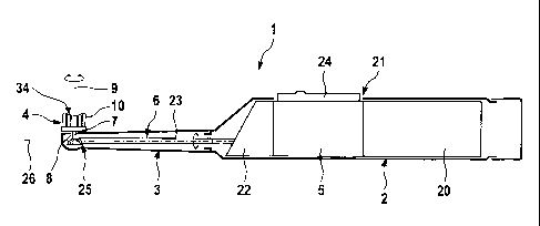
FIG. 1 is a schematic side view of an electric toothbrush having a
rotationally drivable
brush head according to a preferred embodiment of the invention;
FIG. 2 is a top plan view of the brush head of the toothbrush of FIG. 1;
FIG. 3 is a longitudinal sectional view of the brush head taken along the line
B-B of
FIG. 2 parallel to the longitudinal axis of the toothbrush;
FIG. 4 is a longitudinal sectional view of the brush head of FIG. 2 taken
along the line
A-A of FIG. 2;
CA 02742912 2011-05-04
WO 2010/052659
PCT/1B2009/054905
FIG. 5 is an enlarged side view of one of the outer, longer bristle tufts of
FIG. 3 in an
enlarged schematic representation showing the bevel angles of the tuft;
FIG. 6 is a schematic cross-sectional view of a self-fanning bristle according
to an
advantageous embodiment of the invention having three laterally protruding
longitudinal ribs; and
FIG. 7 is a schematic cross-sectional view of a self-fanning bristle according
to
another advantageous embodiment of the invention having four laterally pro-
truding longitudinal ribs.
The toothbrush 1 shown in FIG. 1 comprises a handpiece 2 and a brush head 4
adapted to be coupled to it. To be more precise, the brush head 4 is adapted
to be
coupled to a neck 3 of the toothbrush 1 connected to the handpiece 2, said
neck
being constructed in the form of a hollow brush tube. However, it would also
be
possible for the brush head 4 to comprise said neck 3 or at least part of it
and to be
adapted to be coupled with it to the handpiece 2.
The handpiece 2 accommodates in its interior an energy source 20, preferably
in the
form of a rechargeable battery, a motor 5, preferably in the form of an
electric motor,
and a control device 21.
In the embodiment shown, the rotary motion of the motor 5 is translated by
means of
a gearing 22 into an oscillatory rotational motion of a drive shaft 23 which
extends
through the neck 3 to the brush head 4. The toothbrush 1 can be activated and
de-
activated with a switch 24 mounted on the handpiece 2.
In known manner using a suitable gearing (preferably a bevel gearing 25 unlike
in the
shown embodiment), at the end of the drive shaft 23 the brush head 4 is set
into an
oscillatory rotational motion about an axis of rotation 9 by a pushrod
transmission,
which axis extends substantially in a direction transverse to the toothbrush
longitudinal axis 26. As this occurs, the angular range swept by the bristle
support 7
of the brush head 4 has a value advantageously in the range of 35 5 ,
approxi-
mately, with an oscillation in the range from 10 to 100 being also
possible. The
oscillation frequency can vary and lie, for example, between 10 Hz and 100 Hz.
In the
embodiment shown in FIG. 1, the axis of rotation 9 forms a right angle with
the
toothbrush longitudinal axis 26. In addition, a drive of the brush head 4 is
provided in
CA 02742912 2011-05-04
WO 2010/052659
PCT/1B2009/054905
16
a third dimension for its pulsing motion in the direction of the axis of
rotation or
oscillation.
A preferred embodiment of the brush head 4 of the toothbrush 1 is shown in
FIGS. 2
to 5. In this embodiment, the bristle support 7 is round, however
advantageously not
circular but slightly oval and/or elliptical, with the longer axis of the oval
or the ellipse
in the neutral position of the bristle support 7 extending parallel to the
toothbrush
longitudinal axis 26, and the shorter axis of the oval or the ellipse
extending in a
direction transverse to it. In FIG. 2 the longer axis of the oval or the
ellipse is parallel
to the line B-B.
Arranged on the bristle support 7 is a plurality of bristle tufts which are
arranged in
several rings 12, 14 and 15 shaped in an approximmately circular or non-
circular
(such as oval) configuration and spread over the bristled section 10.
Positioned on an
outer ring 12 in the illustrated embodiment of FIG. 2 are eight tufts, of
which four have
an elongated contour while another four have a - roughly speaking - round or
equilat-
eral cross-sectional contour. The length of the tufts on said outer ring 12
varies, as
will be explained in more detail, with - roughly speaking - longer tufts being
provided
generally in opposing sectors 27 and 28, which in the initial position of the
bristle
support 7 contain the toothbrush longitudinal axis 26, than in sectors 29 and
30, which
are orientated in a direction transverse thereto or lie in between, cf. FIG.
2.
As FIG. 2 shows, the tufts 11 and 31 lying on the outer ring 12 on the main
axes B-B
and A-A, respectively, are elongated in the plan view while the tufts 32 lying
in
between have an approximately equilateral contour or an approximately cubic or
round cross-section. Said elongated tufts 11 and 31 extend in an arcuate curve
around the axis of oscillation or rotation 9, cf. FIG. 2.
In this arrangement, the outer tufts 11 sitting on the longer main axis B-B
extend over
a circumferential section of approximately 50 to 90 , preferably
approximately 70 ,
while the outer tufts 31 sitting on the shorter main axis A-A extend over a
circumferential section of 20 to 45 , approximately, preferably 30 ,
approximately.
Positioned on a second ring 15 of tufts, seen from the outside, are a total of
ten tufts
13a and 13b, of which some have a circular cross-section and others an angular
cross-section. In particular tufts 13a with a circular cross-section are
arranged, as
CA 02742912 2011-05-04
WO 2010/052659
PCT/1B2009/054905
17
shown in FIG. 2, in the sectors 27 and 28 in which the longer outer tufts 11
of the
outer ring 12 lie, while angular tufts are provided in the intermediate
sectors 29 and 30
of the bristle support 7 on the second ring 14. Also, the length of these
tufts 13a and
13b on the second ring 14 varies cyclically from tuft to tuft along the
circumference of
the ring 14, in such a way that longer tufts are provided in said sectors 27
and 28 than
in the sectors 29 and 30 lying on the short main axis.
The round bristle tufts 13a as well as the angular, approximately square
bristle tufts
13b of the middle ring 14 have approximately at least about the same area of
cross-
section regardless of their different cross-sectional contour.
As FIG. 2 shows, to provide favorable space conditions for the securing of the
bristle
tufts, in a further aspect of the invention the angular bristle tufts 13b of
the middle ring
14, at least some of them, may be turned at an acute angle relative to the
main axes
A-A and B-B of the bristle support 7 and also relative to the annular contour
of the ring
14 on which they are arranged. Particularly at least one of the angular
bristle tufts,
preferably each second angular bristle tuft 13b, may have its main axis 37
turned in
such a way that the main axis 37 of the bristle tuft cross-section is inclined
at an acute
angle to a tangent to the middle ring 14. This causes corresponding anchor
plates to
be turned out of the collision range of other anchor plates. In addition, the
flexing
behavior of the bristled section can be made more homogeneous on the whole and
in
particular less dependent on direction.
Finally, in an innermost area or in a third ring of tufts as seen looking from
outside two
elongated bristle tufts 13c are provided which extend with their longitudinal
axis 38
parallel to the longer main axis B-B.
The innermost bristle tufts 13c have a cross-sectional area significantly
greater than
the bristle tufts 13a and 13b of the middle ring. In the embodiment shown,
their cross-
sectional area amounts to between 200% and 400% of the cross-sectional area of
the
bristle tufts 13a and 13b of the middle ring 14.
In this arrangement, the innermost bristle tufts 13c are of an elongated
configuration
so that their longitudinal dimension 38 amounts to more than 150% of their
transverse
dimension, preferably 150% to 300%, approximately. In the embodiment shown,
the
innermost bristle tufts 13c advantageously have an outer contour curved in
convex
CA 02742912 2011-05-04
WO 2010/052659 PC
T/IB2009/054905
18
shape while an inner contour is straight, with the inner and outer contours
being
advantageously connected by rounded end contours.
Advantageously, the innermost bristle tufts 13c have their longitudinal axes
38 aligned
parallel to the main axis of the bristle support which in the non-deflected
neutral
position of the bristle support 7 extends parallel to the toothbrush
longitudinal axis 26
or a longitudinal center plane passing therethrough. The tufts form with their
free
bristle ends a homogeneous bristle surface. This is achieved by the provision
of
tufting hole walls which are slightly inwardly inclined (at an angle of
between 1.5 and
30).
As FIG. 3 shows, the tufts of the bristled section 10 have their free ends
contoured or
coordinated with each other with regard to their length and/or height, such
that the
working surface 34 of the bristled section 10 as defined by the free ends of
the tufts
has a central depression 16 with a groove-shaped bottom 17 which is curved in
one
direction and straight in a direction vertical to it. The curvature extends
advan-
tageously in the direction of the longer main axis B-B or in the direction of
the
toothbrush longitudinal axis 26 when the bristle support 7 is in its non-
deflected
neutral position. In a direction perpendicular thereto, which extends parallel
to the
shorter main axis A-A of the bristle support 7 and/or transverse to the
toothbrush
longitudinal axis 26 when the bristle support 7 is in its non-deflected
neutral position,
the depression 16 has a straight contour as shown in FIG. 3.
The central depression 16 can be constructed to be variously deep. In an
advanta-
geous further aspect of the invention, the deepest point of the depression 16
is set an
amount of approximately 1 mm to 3 mm, preferably approximately 2 mm, deeper
than
the highest point of the bristled section 10. The groove-shaped contour of the
bottom
17 of the depression 16 generally can have different curvatures. In the
embodiment
shown in FIGS. 3 to 5, a circular-arc-shaped contour with a curvature radius
in the
range from 8 mm to 17 mm, preferably approximately 11 mm to 14 mm, is
provided,
but this can vary depending on the dimensions and configuration of the
bristled
section.
As FIG. 3 shows, the end surfaces of the inner tufts 13a, 13b and 13c and the
end
surfaces of the shorter, outer tufts 31, which likewise combine to define the
groove-
shaped bottom 17, are not constructed as plane surfaces but are likewise in
them-
CA 02742912 2011-05-04
WO 2010/052659 PC
T/IB2009/054905
19
selves curved in groove shape. The groove-shaped curved end surfaces 35 com-
plement each other and in combination form said groove-shaped contour of the
bottom 17 of the central depression 16. In concrete terms, the inclination of
the end
surfaces of the inner tufts 13 increases as the distance from the axis of
rotation 9 in
the direction parallel to the main axis B-B increases, cf. FIG. 3. In other
words, the
tufts arranged on the transversally extending main axis A-A are slightly
curved at their
free ends but nevertheless are aligned substantially parallel to the bristle
support
surface, while the inclination of the free ends increases as the distance from
said main
axis A-A increases.
As FIG. 3 also shows, the outer tufts 11 arranged on the outer ring 12 in the
sectors
27 and 28 are extended relative to the other tufts or have a greater height
such that
they project beyond the other tufts. This results in a step in height relative
to the
central depression 16, cf. FIG. 3, that is, the central depression 16 in the
embodiment
shown in FIG. 3 does not merge smoothly with the end surfaces of said outer
tufts 11.
Said outer tufts 11 in the opposing sectors 27 and 28, which in the neutral
position of
the bristle support contain the toothbrush longitudinal axis 26, have
advantageously
end surfaces 36 that comprise a flat section 19, which is aligned
substantially
vertically to the longitudinal axis of the tufts 11, as well as bevels 18,
which bevel said
end surfaces 36 towards the outside.
As FIG. 5 shows, said bevels 18 extend at an angle yin the range from 20 to
60 ,
preferably 30 to 40 , approximately. The bevels 18 are advantageously so deep
and
wide as to cover approximately 25% to 75% of the width W of the respective
tuft 11.
In this case the width W is understood to be the dimension of the tuft
vertically to its
longitudinal axis and vertically to the longitudinal dimension of the bevel
18, in the
region of the free end of the tuft, cf. FIG. 5. In the embodiment shown in
FIG. 5, the
bevel extends over approximately 1/4 to 3/4 of the width W.
Said longer outer tufts 11 are on the whole of a trapezoidal configuration as
seen in
their longitudinal section. While the inner lying flank of the tuft 11 extends
substan-
tially vertically to the plane defined by the bristle support 7, the outer
lying flank is
inclined towards a vertical on the bristle support 7 at an angle a of
approximately 1.5
to 10 , preferably approximately 3 to 5 , such that the cross-section of the
tuft 11
increases towards its free end, that is, the tuft becomes wider towards its
free end. As
CA 02742912 2011-05-04
WO 2010/052659
PCT/1B2009/054905
a result, a large working surface is obtainable with a limited size of the
bristle support
7. In addition, favorable geometrical proportions result at the free end of
the tuft 11 in
relation to its bevel 18.
In order to embrace the tooth flanks as completely as possible, to distribute
the
brushing pressure over a wide area and to hold dentifrice or the like on the
working
surface 34, the tufts occupy with their free ends advantageously at least 35%
to 55%,
preferably 50% or more of the area defined by the bristle support 7. As FIG. 2
shows,
the tufts on the outer ring 12 can extend over a circumferential section of
2000 to
3000, approximately, when the extension of all tufts is added together. The
second
ring 14 of tufts, seen from the outside, can extend likewise over a
circumference of
altogether 200 to 300 , approximately, when the extension of all tufts along
the
circumference is added together. The innermost tufts can cover with their free
ends
advantageously an area substantially closed over its full surface.
Advantageously, the tufts defining the central depression 16 are equipped at
least
partly with self-fanning bristles, whereby in particular the tufts (13a and
13b) shown in
FIG. 2 of the middle ring 14 and/or the innermost tufts 13c (and where
applicable the
tufts 13a of the middle ring) can comprise such self-fanning bristles.
FIG. 6 shows a preferred embodiment of such a self-fanning bristle with a
cross-
section which generally remains constant over its length and is constructed
advan-
tageously to be cloverleaf-shaped, as shown in FIG. 6. The bristle body 40 com-
prises three laterally protruding longitudinal ribs 41 which protrude from a
core section
42 in star shape towards the outer circumferential side. The longitudinal ribs
41 are
spread evenly over the circumference. Advantageously, the longitudinal ribs 41
have
an outer contour which corresponds to a section of a circular cylinder.
The geometrical proportions are advantageously selected such that an
enveloping
cylinder 43 placed around the longitudinal ribs 41 has an outer diameter
Pouter while an
imaginary core enveloping cylinder 45 inscribed by the grooves 44 lying
between the
longitudinal ribs 41 has a diameter Pinner , with the ratio of Pinner to
Pouter being selected in
the range of 0.5 +/- 0.15.
Furthermore, the calipered outer dimension 4) shown in FIG. 6 is selected
through
suitable construction of the longitudinal ribs 41 such that in the embodiment
shown it
CA 02742912 2011-05-04
WO 2010/052659
PCT/1B2009/054905
21
amounts to 5.75 mil. This results in a ratio of the outer diameter of the
enveloping
cylinder 43 Pouter to said calipered outer dimension (1) in the range from 1.0
to 1.3 and in
particular 1.15.
As FIG. 6 shows, the longitudinal ribs 41 in the three-rib configuration
describe an
outer contour in the form of a pitch cylinder 43 whose diameter corresponds
approximately to the diameter Pinner of said core enveloping cylinder 45.
The bristle is formed advantageously from polyamide, in particular nylon 6.12.
FIG. 7 shows another embodiment of the bristle. The basic concept corresponds
essentially to FIG. 6 so that corresponding reference numerals are used. FIG.
7
differs from FIG. 6 essentially in that instead of three longitudinal ribs 41
four longi-
tudinal ribs 41 are provided and in that the brush body 40 therefore has the
cross-
section of a four-leaf clover. Here too the longitudinal ribs 41 are spread
evenly over
the circumference and are equipped with an outer contour which corresponds to
a
pitch cylinder.
The geometrical proportions are selected such that the ratio of the diameter
Pinner of
the core enveloping cylinder 45 to the diameter Pouter of the outer enveloping
cylinder 43
equals approximately 0.5 +/- 0.15. In this four-ribbed version the ratio of
said diameter
Pouter of the enveloping cylinder 43 to the calipered outer dimension 4)
equals
advantageously 1.10 to 1.30 and in particular approximately 1.20. In the
embodiment
shown, said calipered outer dimension 4) again equals approximately 5.75 mil.
Advantageously, the self-fanning bristles shown in FIGS. 6 and 7 in the
previously
mentioned tufts of the middle ring 14 and the innermost tufts 13c are combined
with
"normal", meaning non-self-fanning bristles, and this advantageously in a
mixing ratio
of 50 +1-10% to 50+1-10%, approximately.
The dimensions and values disclosed herein are not to be understood as being
strictly limited to the exact numerical values recited. Instead, unless
otherwise
specified, each such dimension is intended to mean both the recited value and
a
functionally equivalent range surrounding that value. For example, a dimension
disclosed as "40 mm" is intended to mean "about 40 mm."