Language selection

Search

Patent 2743138 Summary

Third-party information liability

Some of the information on this Web page has been provided by external sources. The Government of Canada is not responsible for the accuracy, reliability or currency of the information supplied by external sources. Users wishing to rely upon this information should consult directly with the source of the information. Content provided by external sources is not subject to official languages, privacy and accessibility requirements.

Claims and Abstract availability

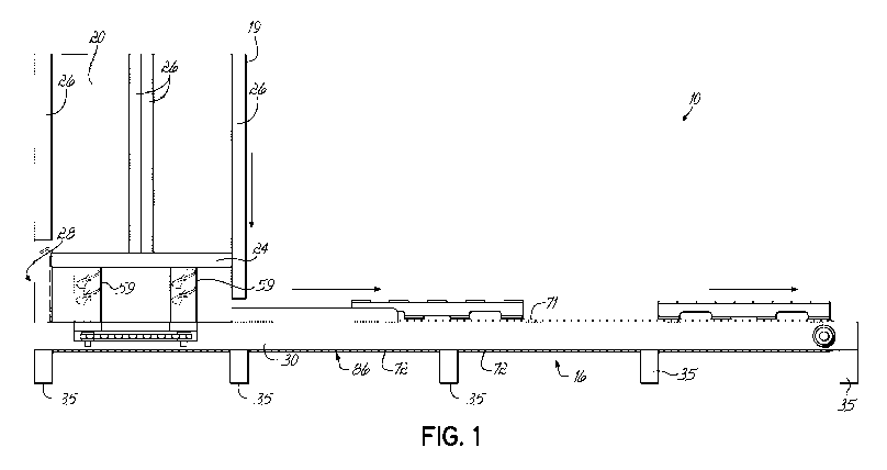
Any discrepancies in the text and image of the Claims and Abstract are due to differing posting times. Text of the Claims and Abstract are posted:

  • At the time the application is open to public inspection;
  • At the time of issue of the patent (grant).
(12) Patent Application: (11) CA 2743138
(54) English Title: PALLET DISPENSER
(54) French Title: DISTRIBUTEUR DE PALETTE
Status: Deemed Abandoned and Beyond the Period of Reinstatement - Pending Response to Notice of Disregarded Communication
Bibliographic Data
(51) International Patent Classification (IPC):
  • B65G 59/06 (2006.01)
(72) Inventors :
  • SNAPP, STEVEN A. (United States of America)
(73) Owners :
  • STEVEN A. SNAPP
(71) Applicants :
  • STEVEN A. SNAPP (United States of America)
(74) Agent: MACRAE & CO.
(74) Associate agent:
(45) Issued:
(86) PCT Filing Date: 2009-10-20
(87) Open to Public Inspection: 2010-05-14
Availability of licence: N/A
Dedicated to the Public: N/A
(25) Language of filing: English

Patent Cooperation Treaty (PCT): Yes
(86) PCT Filing Number: PCT/US2009/061290
(87) International Publication Number: WO 2010053690
(85) National Entry: 2011-05-09

(30) Application Priority Data:
Application No. Country/Territory Date
12/268,085 (United States of America) 2008-11-10

Abstracts

English Abstract


A pallet dispenser (10) includes a frame adapted to support a stack (14) of
pallets (12). The frame includes four
screws (40,42,44,46) with spiral flights (58). The pallets rest on the top
edge of the spiral flights (58) of the screws. Rotation of
the screws then lowers the stack and allows the bottom pallet to drop to a
support below the screws.


French Abstract

L'invention porte sur un distributeur de palette (10), qui comprend un bâti apte à supporter une pile (14) de palettes (12). Le bâti comprend quatre vis (40, 42, 44, 46) avec des vis sans fin en spirale (58). Les palettes reposent sur le bord supérieur des vis sans fin en spirale (58) des vis. La rotation des vis abaisse ensuite la pile et permet à la palette inférieure de tomber sur un support en dessous des vis.

Claims

Note: Claims are shown in the official language in which they were submitted.

-5-
WHAT IS CLAIMED IS:
1. A pallet dispenser comprising a frame defining a pallet holding zone;
a plurality of peripherally spaced screws, each screw having a spirally
shaped flight, said flights positioned to engage and support edges of pallets
stacked
within said pallet holding zone;
a drive attached to each of said screws adapted to rotate said screws
to thereby lower said plurality of pallets and release one pallet at a time.
2. The apparatus claimed in claim 1 comprising four peripherally spaced
screws, two screws on a first side of said frame and two screws on an opposite
second side of said frame.
3. The apparatus claimed in claim 2 wherein said drive includes a drive
chain connected to sprocket on each of said screws.
4. The apparatus claimed in claim 1 further comprising a conveyor below
bottom edges of said screws.
5. The apparatus claimed in claim 4 wherein said conveyor is a chain
conveyor.
6. The apparatus claimed in claim 4 further comprising an electrical
control adapted to synchronize said screws and said conveyor.
7. A method of dispensing pallets from a vertical stack of pallets
comprising positioning a stack of a plurality of pallets on edges of a
plurality of
spaced screws;
rotating said screws whereby a bottom pallet is lowered and released
from said screws while remaining pallets are supported by said screws.
8. The method claimed in claim 7 wherein said screws are driven by a
drive member.
9. The method claimed in claim 8 wherein said drive member is a chain.

-6-
10. The method claimed in claim 7 wherein said rotation of said screw is
synchronized with the rotation of a conveyor positioned to accept and remove
said
pallet from said dispenser.
11. The method claimed in claim 7 wherein said pallets are positioned on
said dispenser with fork openings in said pallets located over said screws.

Description

Note: Descriptions are shown in the official language in which they were submitted.


CA 02743138 2011-05-09
WO 2010/053690 PCT/US2009/061290
PALLET DISPENSER
BACKGROUND OF THE INVENTION
[0001] When products are shipped on pallets, it is necessary to maintain a
supply of pallets. Because pallets are relatively heavy and large, it is
difficult to store
and utilize the pallets.
[0002] Pallet dispensers are used to facilitate storage and use of pallets.
Generally, these pallet dispensers support a stack of pallets and allow one
pallet to
drop from the bottom of the stack of pallets frequently to a conveyor which
then
takes the pallet away for use.
[0003] Pallet dispensers are generally fairly complex. Normally, these pallet
dispensers will include a mechanism to support all but the bottom pallet.
Another
mechanism supports the bottom pallet and, when needed, allows the bottom
pallet
to drop. Such a mechanism can be very expensive, and relatively complex,
having
many different interrelated moving parts. Further, the dispensing mechanism
must
be able to work with a stack of very heavy pallets, weighing a total of 600
pounds or
more. Thus, the weight of a stack of pallets creates issues with respect to a
pallet
dispenser. Further, pallets are frequently broken or irregular, making
dispensing
even more difficult.
SUMMARY OF THE INVENTION
[0004] The present invention is premised on the realization that a screw-type
dispensing mechanism can be used in a pallet dispenser to support a stack of
pallets and dispense these one at a time. The support mechanism includes a
plurality of screws with spiral flights. The spiral flights of these screws
support the
stack of pallets and rotate to lower the pallets until the bottom pallet is
released, with
the remaining pallets still supported by the screws. To dispense additional
pallets,
the screws are, again, synchronously rotated to lower the pallets until the
lowest

CA 02743138 2011-05-09
WO 2010/053690 PCT/US2009/061290
-2-
pallet is released from the screws. These can be dispensed on a conveyer, or
simply dispensed at the bottom to allow an individual to manually remove the
pallet.
[0005] The objects and advantages of the present invention will be further
appreciated in light of the following detailed description and drawings in
which:
BRIEF DESCRIPTION OF THE DRAWING
[0006] FIG. 1 is a side plan view of the present invention.
[0007] FIG. 2 is an overhead plan view of the present invention.
[0008] FIG. 3 is an enlarged side view of the present invention partially
broken
away and partially in phantom.
[0009] FIG 4 is an overhead cross sectional view taken at lines 4-4 of FIG. 1.
[0010] FIG. 5 is a rear plan view of the present invention.
DETAILED DESCRIPTION
[0011] As shown in the figures, the present invention is a pallet dispenser
10,
which is adapted to dispense a bottom most pallet 12 from a stack of pallets
14.
The pallets are dispensed onto a chain conveyor 16.
[0012] The pallet dispenser 10 has three solid sides or walls 18,19,20 with
braces 26, and lower and upper horizontal frame members 22,24 on each side of
walls 18 and 20. These walls 18,19,20 define the pallet holding zone for the
pallet
dispenser 10, i.e., the area taken up by the stack of pallets 14. As shown
(FIG. 5)
walls 18 and 20 are sloped inwardly from top to bottom to facilitate aligning
the
pallets.
[0013] A lower portion 28 beneath the pallet holding zone includes first and
second horizontal members 30 and 32. Lateral frame members 34 and 36 extend
between members 30 and 32. Horizontal frame members 30,32 act as side frame
supports of conveyor 16. Members 30 and 32 are generally C-shaped beams
supported by legs 35.
[0014] The pallet dispenser further includes four screws 40,42,44,46. An
upper end 48 of each screw is attached to a bushing 50, located at its upper
end in
horizontal members 22 and 24. The lower end 52 of each screw is attached to
frame members 30 and 32 by pillow bearings 54. As shown, the screws each
include a vertical shaft 56 and a spiral flight 58. The vertical shaft 56
remains

CA 02743138 2011-05-09
WO 2010/053690 PCT/US2009/061290
-3-
outside of the pallet holding zone, while the flight 58 of each of the screws
extends
into the pallet holding zone. Guards 59 surround the exterior of the screws.
[0015] The flights of the screws have a leading edges 92 immediately below
horizontal cross members 22 and 24. The flights extend spirally downwardly
with a
bottom edge 94 spaced from the conveyor 16 a distance slightly greater than
the
thickness of the pallets. Thus, a pallet 12 can move underneath the bottom
edges
94 of the screws to be moved by conveyor 16 without engaging the screws.
[0016] At the bottom of each shaft 56 below bearings 54 is a chain sprocket
67. A continuous chain 60 connects the sprockets of all four screws. The chain
is
driven by motor 62, which attaches to a beveled gear member 64 attached to a
drive
sprocket 66. The gear and motor are attached to an adjustable mounting plate
68,
which is adjustably fixed to cross member 70. The screw drive chain 60 runs
through openings 61 in first and second frame members 30 and 32 around
sprockets 67, and around drive sprocket 66 so that all sprockets 67 and 68
operate
synchronously.
[0017] Chain conveyor 16 is located in the lower portion 28 with the upper run
71 above drive chain 60, and the lower run 72 below drive chain 60. Rear slave
axel
74 of conveyor 16 runs between members 30 and 32 with the slave sprockets 76
and 78 spaced inwardly and below the pallet holding zone. Conveyor 16 in turn
is
driven by motor 88, which can be operated by a control unit 90.
[0018] In use, the pallet dispenser 10 is loaded by inserting the pallets 14
from the back side 96 of the dispenser 10. These pallets 14, as shown, have
openings 98 for forks of a fork lift, to permit movement of the pallets. The
fork
openings 98 are positioned directly above the four screws 40,42,44,46 so that
the
bottom edge 100 of the fork openings 98 rests on the leading edge 92 of the
flights
of the screws.
[0019] The pallets are dispensed by rotating the screws, using the motor 62,
which rotates drive sprocket 66, which in turn drives the chain 60, in turn
rotating all
four of the screws at the same speed. The flights of the screws are aligned so
that
the leading edge 92 of each screw is at the same location relative to the
sides of the
pallets to permit a pallet to be lowered in a level orientation.
[0020] Once the pallets are positioned in the pallet holding zone in the
frame,
the screws are then rotated, as shown by arrow 102, in a clockwise direction,
which
will lower the entire stack of pallets. The bottom pallet 12, once it extends
below the
bottom edges 94 of the screws, will drop onto the conveyor chains 84 and 86.
The

CA 02743138 2011-05-09
WO 2010/053690 PCT/US2009/061290
-4-
bottom pallet 12 is then removed. Continued rotation of the screws will lower
additional pallets.
[0021] Preferably, as shown, the pallet dispenser is used with conveyor 16.
As shown in FIG. 2, the conveyor motor 88, and the motor 62 for the pallet
dispenser, can both be controlled by a single control unit 90, which will
cause the
pallet dispenser 10 to operate synchronously with the conveyor 16. The pallet
dispenser will dispense a pallet only when the conveyor is not moving. The
control
unit 90 can further be used to speed up the conveyor and pallet dispenser, or
to
slow down the conveyor and pallet dispenser, or to change their relative
speeds.
[0022] The pallet dispenser, as previously described, has several advantages.
The screw support system for the pallets is extremely sturdy. It does not
require a
second mechanism to support the stack of pallets while the lower pallet is
dispensed
with a separate apparatus. Because it uses a single drive chain to operate the
dispenser, synchronization is inherent. Also, because the pallets are
supported and
dispensed on a spiral flight, irregularities in the pallet will not interfere
with the
operation of the pallet dispenser. The pallet dispenser will function with
broken
pallets or improperly manufactured pallets.
[0023] The pallet dispenser has been described in combination with a
conveyor. However, it can be used without a conveyor, if preferred. For
example,
the pallets could be dispensed onto a slide and manually removed from the
slide.
[0024] This has been a description of the present invention along with the
preferred method of practicing the present invention. However, the invention
itself
should only be defined by the appended claims.

Representative Drawing
A single figure which represents the drawing illustrating the invention.
Administrative Status

2024-08-01:As part of the Next Generation Patents (NGP) transition, the Canadian Patents Database (CPD) now contains a more detailed Event History, which replicates the Event Log of our new back-office solution.

Please note that "Inactive:" events refers to events no longer in use in our new back-office solution.

For a clearer understanding of the status of the application/patent presented on this page, the site Disclaimer , as well as the definitions for Patent , Event History , Maintenance Fee  and Payment History  should be consulted.

Event History

Description Date
Application Not Reinstated by Deadline 2015-10-20
Inactive: Dead - RFE never made 2015-10-20
Inactive: Abandon-RFE+Late fee unpaid-Correspondence sent 2014-10-20
Inactive: Cover page published 2011-07-14
Inactive: Inventor deleted 2011-06-30
Inactive: Notice - National entry - No RFE 2011-06-30
Inactive: First IPC assigned 2011-06-29
Application Received - PCT 2011-06-29
Inactive: IPC assigned 2011-06-29
National Entry Requirements Determined Compliant 2011-05-09
Small Entity Declaration Determined Compliant 2011-05-09
Application Published (Open to Public Inspection) 2010-05-14

Abandonment History

There is no abandonment history.

Maintenance Fee

The last payment was received on 2014-09-18

Note : If the full payment has not been received on or before the date indicated, a further fee may be required which may be one of the following

  • the reinstatement fee;
  • the late payment fee; or
  • additional fee to reverse deemed expiry.

Patent fees are adjusted on the 1st of January every year. The amounts above are the current amounts if received by December 31 of the current year.
Please refer to the CIPO Patent Fees web page to see all current fee amounts.

Fee History

Fee Type Anniversary Year Due Date Paid Date
Basic national fee - small 2011-05-09
MF (application, 2nd anniv.) - small 02 2011-10-20 2011-09-27
MF (application, 3rd anniv.) - small 03 2012-10-22 2012-09-24
MF (application, 4th anniv.) - small 04 2013-10-21 2013-09-20
MF (application, 5th anniv.) - small 05 2014-10-20 2014-09-18
Owners on Record

Note: Records showing the ownership history in alphabetical order.

Current Owners on Record
STEVEN A. SNAPP
Past Owners on Record
None
Past Owners that do not appear in the "Owners on Record" listing will appear in other documentation within the application.
Documents

To view selected files, please enter reCAPTCHA code :


To view images, click a link in the Document Description column. To download the documents, select one or more checkboxes in the first column and then click the "Download Selected in PDF format (Zip Archive)" or the "Download Selected as Single PDF" button.

List of published and non-published patent-specific documents on the CPD .

If you have any difficulty accessing content, you can call the Client Service Centre at 1-866-997-1936 or send them an e-mail at CIPO Client Service Centre.


Document
Description 
Date
(yyyy-mm-dd) 
Number of pages   Size of Image (KB) 
Drawings 2011-05-08 4 102
Claims 2011-05-08 2 42
Abstract 2011-05-08 1 51
Description 2011-05-08 4 177
Representative drawing 2011-05-08 1 12
Reminder of maintenance fee due 2011-06-29 1 114
Notice of National Entry 2011-06-29 1 196
Reminder - Request for Examination 2014-06-22 1 116
Courtesy - Abandonment Letter (Request for Examination) 2014-12-14 1 164
PCT 2011-05-08 6 258