Language selection

Search

Patent 2743372 Summary

Third-party information liability

Some of the information on this Web page has been provided by external sources. The Government of Canada is not responsible for the accuracy, reliability or currency of the information supplied by external sources. Users wishing to rely upon this information should consult directly with the source of the information. Content provided by external sources is not subject to official languages, privacy and accessibility requirements.

Claims and Abstract availability

Any discrepancies in the text and image of the Claims and Abstract are due to differing posting times. Text of the Claims and Abstract are posted:

  • At the time the application is open to public inspection;
  • At the time of issue of the patent (grant).
(12) Patent: (11) CA 2743372
(54) English Title: FUSELAGE STRUCTURE MADE OF COMPOSITE MATERIAL
(54) French Title: STUCTURE DE FUSELAGE EN MATERIAU COMPOSITE
Status: Deemed Expired
Bibliographic Data
(51) International Patent Classification (IPC):
  • B64C 01/00 (2006.01)
(72) Inventors :
  • BUCHS, WOLFGANG (Germany)
  • DREHER, GABRIELE (Germany)
  • GIRARD, UMBERTO (Germany)
  • KUNZE, STEFFEN (Germany)
  • THIESS, THOMAS (Germany)
(73) Owners :
  • AIRBUS HELICOPTERS DEUTSCHLAND GMBH
(71) Applicants :
  • AIRBUS HELICOPTERS DEUTSCHLAND GMBH (Germany)
(74) Agent: FASKEN MARTINEAU DUMOULIN LLP
(74) Associate agent:
(45) Issued: 2013-12-31
(22) Filed Date: 2011-06-16
(41) Open to Public Inspection: 2012-02-02
Examination requested: 2011-07-11
Availability of licence: N/A
Dedicated to the Public: N/A
(25) Language of filing: English

Patent Cooperation Treaty (PCT): No

(30) Application Priority Data:
Application No. Country/Territory Date
10 400035.1 (European Patent Office (EPO)) 2010-08-02

Abstracts

English Abstract


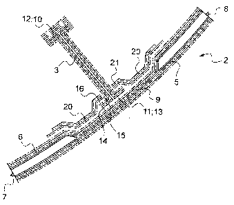
A fuselage structure is disclosed. The fuselage comprises at
least one panel and at least one beam mounted to each other and
the panel with the panel being formed of at least one group of
composite layers. The at least one beam is provided at least at the
one of its respective ends with a flange adhesively engaged with
the at least one panel. The at least one group of composite layers
of the panel is in form locking engagement with this flange of the
beam. The at least one panel is provided with sandwich element
apart from the areas of contact between the at least one panel and
the at least one beam.


French Abstract

Une structure de fuselage est présentée. Le fuselage comprend au moins un panneau et au moins un montant fixé entre eux et au panneau, le panneau étant formé d'au moins un groupe de couches de composite. Le au moins un montant comporte au moins à une de ses extrémités respectives une bride engagée par adhésion avec le au moins un panneau. Le au moins un groupe de couches de composite du panneau est en engagement de blocage de forme avec cette bride du montant. Le au moins un panneau comporte un élément intercalaire indépendant des zones de contact entre le au moins un panneau et le au moins un montant.

Claims

Note: Claims are shown in the official language in which they were submitted.


7
CLAIMS:
1. A fuselage structure comprising at least one panel and
at least one beam mounted to each other and the panel with the
panel being formed of at least one group of composite layers)
characterized in that the at least one beam is provided at
least at one of its respective ends with a flange adhesively
engaged with the at least one panel and in that the at least one
group of composite layers of the panel is in form locking
engagement with this flange of the beam, said at least one panel
being provided with sandwich elements apart from the areas of
contact between the at least one panel and the at least one beam..
2. A fuselage structure according to claim 1, characterized
in that the at least one group of composite layers of the panel is
overlapping onto the flange of the beam for the form locking
engagement.
3. A fuselage structure according to claim 1, characterized
in that the at least one end of the at least one beam is T-shaped.
4. A fuselage structure according to claim 1, characterized
in that the at least one group of composite layers of the panel is
interrupted for the form locking engagement with the flange of the
beam.
5. A fuselage structure according to claim 1, characterized
in that the at least one panel is formed of two groups of composite
layers.
6. A fuselage structure according to claim 5, characterized
in that the at least one panel is formed with an extra group of
composite layers inside of the two groups of composite layers.

8
7. A fuselage structure according to claim 5, characterized
in that the inner layer of the panel is interrupted for the interlocking
engagement with the flange of the beam.
8. A fuselage structure according to claim 1, characterized
in that the at least one beam is provided with an essentially even
outer surface and an essentially even inner surface at its flange,
the outer group of composite layers being interrupted with a hole
through which the beam is reaching such that the essentially even
inner surface at its flange is mounted to the outside of the outer
group of composite layers and the outer group of composite layers
with the hole is overlapping partly the even inner surface for form
lock with flange.
9. A fuselage structure according to claim 8, characterized
in that flange is provided at its even outer surface with additional
composite layers.
10. A fuselage structure according to claim 1, characterized
in that it is an aircraft door of composite material.
11. A fuselage structure according to claim 1, characterized
in that it is an aircraft passenger door of composite material.

Description

Note: Descriptions are shown in the official language in which they were submitted.


CA 02743372 2011-06-16
Fuselage Structure made of composite Material
The present application claims the benefit of European patent
application EP 10 400035.1 filed on August 2, 2010, the disclosure
of which is incorporated herein by reference.
The present invention relates to a fuselage structure made of
composite material, particularly aircraft doors of composite material
and especially it relates to passenger doors of an aircraft with the
features of the preamble of claim 1.
During a flight at cruising altitude an air excess pressure of
0,6 bar inside a fuselage of an aircraft relative to the surrounding
is provided on behalf of the comfort of the passengers. The excess
pressure inside the fuselage is withheld by a skin formed of panels
attached to an inner frame structure such as beam elements of the
fuselage. The excess pressure on the skin of the fuselage exerts a
severing effect of the skin from the inner frame structure of the
fuselage. Aircraft doors as part of the fuselage are exposed to the
same severing effects. Aircraft doors have to be highly reliable
with respect to pressure resistance (typ. 10pwr-9/flighthour). In
case of an emergency landing aircraft doors have to open highly
reliable (typ. 10pwr-7/flighthour).
It is known to mount aircraft doors of composite material by
riveting the panels to the beam elements of the frame structure of
such an aircraft door. The rivets carry out and distribute the loads
generated by internal pressure and deformations due to flight
loads. Such rivets increase the manufacturing cost and the
combination "rivets-composites" increase maintenance issues.

CA 02743372 2011-06-16
2
It is an object of the present invention to provide for highly
reliable fuselage structure made of composite material with low
weight and low production costs.
The invention is solved with a fuselage structure made of
composite material with the features of claim 1. Preferred
embodiments of the invention are presented in the subclaims.
According to the invention a fuselage structure made of
composite material, particularly a passenger door of an aircraft is
provided with at least one panel and an inner frame structure
mounted to each other. The panel is formed of at least one layer or
preferably at least one group of layers of composite material. The
inner frame structure is provided with at least one beam with at
least at one of its respective ends a flange suitable for adhesive
engagement with the at least one panel. At least one group of
layers of composite material of the panel is in form locking
engagement with this flange of the beam. The invention allows
highly reliable aircraft doors of composite material with low weight
and low production costs by transferring loads from inner excess
pressure by means of form lock supplemental to adhesive mounting
between panels of the skin and inner structural elements such as
beams or frames of a fuselage. Expensive and heavy rivets can be
avoided according to the inventive concept. All kinds of fiber
reinforced plastics as well as additional adhesive layers (e.g. film
adhesives) may be applied for bonding the respective layers in
addition to form lock. A one-shot technology in e. g. Resin Transfer
Molding could be chosen for optimized low weight and low
production costs of the inventive aircraft door.
According to a preferred embodiment of the invention at least
one group of layers of composite material of the panel and the
flange of the beam are overlapping each other for the form locking
engagement.

CA 02743372 2011-06-16
3
According to another preferred embodiment of the invention
at least one end of the at least one beam is T-shaped.
According to another preferred embodiment of the invention
at least one group of layers of composite material of the panel is
interrupted for the form locking engagement with the flange of the
beam.
According to another preferred embodiment of the invention
at least one panel is provided with two groups of layers of
composite material or with an extra group of layers inside of the
two groups of layers of composite material with the inner layers of
composite material of the panel being interrupted for the
interlocking engagement with the flange of the beam. The extra
inner group of layers of composite material inside the two groups of
layers of composite material of the panel may preferably be used
for reinforcement of the connections between the panel and the
beams of the inner frame structure and in order to prevent peeling
effects.
According to another preferred embodiment of the invention
the at least one panel is provided with sandwich elements apart
from the areas of contact between the at least one panel and the at
least one beam. The sandwich elements extend along sections of
the panels to reinforce the panels.
According to another preferred embodiment of the invention
the at least one beam is provided with respective even outer
surfaces and an even inner surface mounted to the outside of the
outer composite layers being interrupted with a cut-out to provide
overlapping parts for form lock with the even inner surface of the
flange. The flange is provided at its even outer surface with
additional composite layers to maintain stability and stiffness of the
outer skin assembly.

CA 02743372 2011-06-16
4
A preferred embodiment of the invention is presented in the
attached drawings:
Fig. 1 shows a cross sectional view of an aircraft door
according to the state of the art,
Fig. 2shows a frontal view of an aircraft door according to the
state of the art,
Fig. 3 shows a schematic view through a section of an
aircraft door according to the invention,
Fig. 4 shows a schematic view through a further section of an
aircraft door according to the invention, and
Fig. 5 shows a schematic view through another section of an
aircraft door according to the invention.
Detailed Description of the Preferred Embodiments
Fig. 1, 2: An aircraft door 1 of composite material, particularly
a passenger door is provided with panels 2 forming an outer skin
and beams 3 and frames 4 forming an inner frame structure.
Sandwiches 7, 8 are provided at sections of the panels 2. Beams 3
and frames 4 are fitted to each other and are fitted essentially
vertical to the panels 2 at areas without sandwiches 7, 8. All beams
3 and frames 4 are monolithic laminates. For mounting of the
aircraft door 1 to the fuselage (not shown) the outer curvature of
the aircraft door 1 is adapted to the outer shape of the fuselage.
Fig. 3: Corresponding features are referred to with the
numerals of Fig. 1,2. The panel 2 is formed of a first group of
layers 5 of composite material for an outer skin and a second inner
group of layers 6 of composite material. Composite layers 5, 6 form
first and second sandwich structures 7, 8. Between the first and
second sandwich structures 7, 8 the two groups 5, 6 of layers of

CA 02743372 2011-06-16
composite material are cured together to a monolithic panel section
9. An extra group of layers 20 of composite material is attached
inside of the monolithic panel section 9 overlapping parts of the
first and second sandwich structures 7, 8.
5 One beam 3 of the inner frame structure is provided at its
respective ends 10, 11 with flanges 12, 13 with respective even
outer surfaces 14. Flange 13 is adhesively engaged with its even
outer surface 14 to the inside of the monolithic panel section 9.
The extra group of layers 20 of composite material attached inside
of the monolithic panel section 9 is interrupted with a cut-out 15.
The dimensions of the cut-out 15 are smaller than the dimensions
of flange 13 to provide overlapping parts 21 of the extra group of
layers 20 of composite material for form lock with an even inner
surface 16 of the flange 13.
Fig. 4: Corresponding features are referred to with the
numerals of Fig. 1, 2 and 3. The panel 2 is formed of an outer
group of layers 5 of composite material and an inner group of
layers 6 of composite material. Composite layers 5, 6 are formed to
first and second sandwich structures 7, 8. Between the first and
second sandwich structures 7, 8 the two groups of composite
layers 5, 6 are cured together to monolithic panel sections 17, 18.
The beam 3 of the inner frame structure is provided at its
respective ends 10, 11 with flanges 12, 13 with respective even
outer surfaces 14. Flange 13 is adhesively and potentially
rectangular fixed with its even outer surface 14 to the outer
composite layer 5 between the monolithic panel sections 17, 18.
The inner composite layer 6 between the monolithic panel sections
17, 18 is interrupted with a hole 15 to provide overlapping parts 21
for form lock with the even inner surface 16 of flange 13.

CA 02743372 2011-06-16
6
Fig. 5: Corresponding features are referred to with the
numerals of Fig. 1 - 4. The panel 2 is formed of an outer group of
composite layers 5 and an inner group of composite layers 6
forming first and second sandwich structures 7, 8. Between the first
and second sandwich structures 7, 8 the inner and outer groups of
composite layers 5, 6 are cured together to monolithic panel
sections 17, 18.
The beam 3 is provided with an even outer surface 14 and an
even inner surface 16 at its flange 13. The outer group of
composite layers 5 is interrupted with a cut-out 15 through which
the beam 3 is reaching such that the even inner surface 16 at its
flange 13 is essentially rectangular fixed to the outside of the outer
group of composite layers 5. The outer group of composite layers 5
is at the hole 15 overlapping partly the even inner surface 16 for
form lock with flange 13. Flange 13 is provided at its even outer
surface 14 with additional composite layers 19.
Combinations of the embodiments according to Fig. 3 - 5 are
within the scope of the invention.
All groups of composite layers 5, 6 and 20 are monolithic
laminates. For reduced weight and reduced costs Resin Transfer
Molding (RTM) also known as Resin-Injection Process using a
closed-mold pressure injection system process was applied in
combination with the so-called one-shot technology (detailed in:
Plastverarbeiter 2002, No. 12, page 62).

Representative Drawing
A single figure which represents the drawing illustrating the invention.
Administrative Status

2024-08-01:As part of the Next Generation Patents (NGP) transition, the Canadian Patents Database (CPD) now contains a more detailed Event History, which replicates the Event Log of our new back-office solution.

Please note that "Inactive:" events refers to events no longer in use in our new back-office solution.

For a clearer understanding of the status of the application/patent presented on this page, the site Disclaimer , as well as the definitions for Patent , Event History , Maintenance Fee  and Payment History  should be consulted.

Event History

Description Date
Letter Sent 2023-12-18
Letter Sent 2023-06-16
Change of Address or Method of Correspondence Request Received 2020-01-17
Common Representative Appointed 2019-10-30
Change of Address or Method of Correspondence Request Received 2019-08-14
Letter Sent 2014-05-27
Grant by Issuance 2013-12-31
Inactive: Cover page published 2013-12-30
Pre-grant 2013-10-18
Inactive: Final fee received 2013-10-18
Notice of Allowance is Issued 2013-09-23
Letter Sent 2013-09-23
Notice of Allowance is Issued 2013-09-23
Inactive: Approved for allowance (AFA) 2013-09-20
Amendment Received - Voluntary Amendment 2013-05-29
Inactive: S.30(2) Rules - Examiner requisition 2012-12-07
Application Published (Open to Public Inspection) 2012-02-02
Inactive: Cover page published 2012-02-01
Letter Sent 2012-01-16
Inactive: IPC assigned 2012-01-13
Inactive: First IPC assigned 2012-01-13
Letter Sent 2011-12-05
Inactive: Single transfer 2011-11-21
Inactive: Filing certificate - No RFE (English) 2011-09-16
All Requirements for Examination Determined Compliant 2011-07-11
Request for Examination Requirements Determined Compliant 2011-07-11
Request for Examination Received 2011-07-11
Inactive: Filing certificate - No RFE (English) 2011-07-04
Application Received - Regular National 2011-07-04

Abandonment History

There is no abandonment history.

Maintenance Fee

The last payment was received on 2013-06-11

Note : If the full payment has not been received on or before the date indicated, a further fee may be required which may be one of the following

  • the reinstatement fee;
  • the late payment fee; or
  • additional fee to reverse deemed expiry.

Patent fees are adjusted on the 1st of January every year. The amounts above are the current amounts if received by December 31 of the current year.
Please refer to the CIPO Patent Fees web page to see all current fee amounts.

Owners on Record

Note: Records showing the ownership history in alphabetical order.

Current Owners on Record
AIRBUS HELICOPTERS DEUTSCHLAND GMBH
Past Owners on Record
GABRIELE DREHER
STEFFEN KUNZE
THOMAS THIESS
UMBERTO GIRARD
WOLFGANG BUCHS
Past Owners that do not appear in the "Owners on Record" listing will appear in other documentation within the application.
Documents

To view selected files, please enter reCAPTCHA code :


To view images, click a link in the Document Description column. To download the documents, select one or more checkboxes in the first column and then click the "Download Selected in PDF format (Zip Archive)" or the "Download Selected as Single PDF" button.

List of published and non-published patent-specific documents on the CPD .

If you have any difficulty accessing content, you can call the Client Service Centre at 1-866-997-1936 or send them an e-mail at CIPO Client Service Centre.


Document
Description 
Date
(yyyy-mm-dd) 
Number of pages   Size of Image (KB) 
Description 2011-06-15 6 242
Claims 2011-06-15 2 60
Abstract 2011-06-15 1 14
Drawings 2011-06-15 3 67
Representative drawing 2012-01-24 1 15
Claims 2013-05-28 2 63
Abstract 2013-05-28 1 16
Filing Certificate (English) 2011-07-03 1 157
Filing Certificate (English) 2011-09-15 1 156
Courtesy - Certificate of registration (related document(s)) 2011-12-04 1 104
Acknowledgement of Request for Examination 2012-01-15 1 177
Reminder of maintenance fee due 2013-02-18 1 112
Commissioner's Notice - Application Found Allowable 2013-09-22 1 163
Commissioner's Notice - Maintenance Fee for a Patent Not Paid 2023-07-27 1 540
Fees 2013-06-10 1 156
Courtesy - Patent Term Deemed Expired 2024-01-28 1 537
Correspondence 2013-10-17 2 65