Note: Descriptions are shown in the official language in which they were submitted.
CA 02744208 2011-05-19
WO 2010/058194
PCT/GB2009/051501
- 1 -
Target Scene Generator
Field of the invention
The present invention relates to a target scene generator, for use in
testing pulsed laser sensing apparatus that may be incorporated into flying
objects such as missiles.
Background art
It is common to incorporate seekers into missiles, for guiding the missile
onto a target. When a new missile is being developed it must be tested to
ensure that the design is robust and that it behaves the way it is expected
to.
Tests are carried out at all stages of development on the components and sub-
systems, but a test is needed for the complete, assembled missile, in order to
check that the sub-systems work together as intended, and that the missile is
capable of doing the job it is required to do. The missile sub-systems can be
tested simultaneously in a representative environment by firing the missile
against a test target at a missile firing range. This is an essential part of
any
new missile development programme, although it is very expensive and time
consuming. A way of significantly reducing the number of missile firings
required is to use validated representative performance models. Hardware In
The Loop (HWIL) testing allows the interaction and response of many of the
missile sub-systems to be tested repeatedly in a controlled environment, at
much lower cost and with much faster timescales than firing trials, to provide
confidence in both the models and the missile sub-systems.
Guided missiles contain a seeker for autonomous target tracking and
interception. The seeker contains a detector that responds to electromagnetic
radiation, either RF, optical or infrared, that is emitted or scattered by the
target.
Target radiation detected by the seeker is used to determine target bearing
and
motion, and thus to determine the necessary guidance commands to direct the
CA 02744208 2011-05-19
WO 2010/058194
PCT/GB2009/051501
- 2 -
missile's motion. If the guidance is correct the missile controller will use
the
seeker information to steer the missile on a trajectory that will intercept
the
target. HWIL testing simulates this process in a controlled manner in the
following way. The front of the missile containing the seeker, i.e. real
hardware,
is mounted in a cradle that is able to rotate about all three axes. A
representative image of a target at a particular range is then projected to
the
missile seeker to simulate a real target, by means of a target scene
generator.
The target scene generator is also mounted so that it can be rotated in
azimuth
and elevation, relative to the seeker, to simulate target motion.
The missile seeker responds to the simulated movement and bearing of
the target image and sends data to a missile controller, which then determines
appropriate guidance signals to send to other missile sub-systems, such as the
actuators for the fins. The overall aerodynamic and kinetic response of the
missile to these guidance signals is then modelled, to determine the angular
motion to be imposed on the 3-axis cradle, and the effect on the image of the
target due to the modelled aerodynamic kinetic response of the missile. Any
required changes to the simulated position and motion of the target image are
input to the scene generator, which then projects a modified image to the
seeker, and then the cycle is repeated. This arrangement is referred to as
closed-loop testing, as the consequences of the signals from the missile
controller are fed into the target scene generator, which changes the image
seen by the seeker and thus the input to the controller, which affects the
target
scene again, and so on, without operator intervention. Testing is also
performed in real-time. The simulated target image grows larger as time
progresses, representing the missile's flight towards the target. If the
missile is
operating correctly the cyclical process allows the complete target engagement
to be tested from launch to the point where the missile fuze would be expected
to operate. The sub-systems not normally tested by this process are the fuze,
the warhead, and the motors.
The target scene generator is a key component of HWIL testing.
However, there are currently limitations on the types of seeker that can be
tested in this way. In this regard, HWIL systems for testing missiles with
optical
CA 02744208 2014-01-10
26158-293
- 3 -
or infrared seekers typically only test "passive" seekers i.e. where the
seeker
passively views the radiation emitted by the scene, and does not provide its
own radiation to illuminate or floodlight the scene. By contrast "active"
seekers
contain their own radiation sources. to provide scene illumination, and
respond
only to the wavelengths of those generated sources. Such active seekers
based on laser radar include at least one laser source, and detect only laser
wavelengths in a selected narrow-band so that the effect of ambient
background noise radiation is reduced. The laser source may be carried by a
missile or may be a semi-active laser (SAL). In this latter case, the laser
emitter
may carried by an aircraft or ground personnel and used to illuminate a target
for detection by the sensor of the missile.
Testing of such active War seekers in HWIL arrangements is not
feasible with typical HWIL test equipment, however, because known target
scene generators are not capable of generating an image in the format that an
active ladar seeker can recognise.
Testing of SAL seekers in HWIL arrangements is similarly not feasible
with typical HWIL test equipment. Even though a SAL sensor is 'passive' and
does not carry its won laser source, it responds only to pulsed laser
radiation,
and thus requires a target scene generator that can provide the required laser
pulses with the correct timing from the different parts of the SAL's seeker's
field
of view.
Equipment for HWIL testing of ladar seekers is known to be in
development, although such test equipment is typically based on a target scene
generated by an array of independent, actively controlled light sources.
Summary of the invention
Some embodiments of the invention may provide a target scene generator
for use in testing pulsed laser sensing apparatus for incorporation into
flying objects
such as missiles.
CA 02744208 2014-01-10
26158-293
- 4 -
In one embodiment, the invention provides a target scene generator for
generating a target scene, for use in testing pulsed laser sensing apparatus
for
incorporation in a flying object, the generator comprising an array of pixel
elements, detector means for detecting operation of a pulsed laser, light
source
means for generating at least one pulse of light representing a returned laser
pulse, and a reconfigurable optical waveguide network selectively coupling
said
: light source means to said pixel elements,
and a controller means being operative to selectively reconfigure said
waveguide network, whereby to present to selected pixel elements said one
pulse of light and said controller means being operative so that said one
pulse
of light is provided with selected time delay characteristics such that light
emitted from said pixels represent the returned optical signals from a target
illuminated by said apparatus.
In another embodiment, the invention provides a method of generating a
target scene for testing pulsed laser sensing apparatus that is to be
incorporated in a flying object, the method comprising:
detecting operation of a pulsed ladar and providing, in response to said
detecting, at least one pulse of light representing a returned laser pulse,
providing an array of pixel elements and providing a reconfigurable
optical waveguide network selectively coupling said at least one pulse of
light to
selected ones of said pixel elements for emission therefrom, and
= providing said one pulse with selected time delay characteristics such
that light emitted from said pixels represents the returned optical signals
from a
target illuminated by said apparatus.
CA 02744208 2014-01-10
26158-293
- 4a -
In another embodiment of the invention, there is provided a target
scene generator for generating a target image, for use in testing pulsed laser
sensing
apparatus for incorporation in a flying object, the generator comprising: an
array of
pixel elements, detector means for detecting operation of a pulsed laser,
light source
means for generating at least one pulse of light representing a returned laser
pulse, a
reconfigurable optical waveguide network selectively coupling said light
source
means to respective said pixel elements, the reconfigurable network comprising
a
plurality of optical waveguides for directing light emitted from the light
source means
to any one or more of the plurality of pixel elements in the pixel array and
at least one
switching element for selectively directing light emitted from said light
source means
along any one or more of the optical waveguides in accordance with a target
image to
be generated, and a controller means being operative to selectively
reconfigure said
waveguide network to provide said selective direction of light and present to
selected
pixel elements said at least one pulse of light, and said controller means
being
operative to provide said one pulse with selected time delay characteristics;
light
emitted from said pixels in use representing said target image.
In another embodiment of the invention, there is provided a method of
generating a target image for use in testing pulsed laser sensing apparatus
that may
be incorporated in a flying object, the method comprising: detecting operation
of the
apparatus and providing in response to said detecting at least one pulse of
light
representing a returned laser pulse, providing an array of pixel elements,
providing a
reconfigurable optical waveguide network comprising a plurality of optical
waveguides
for selectively coupling said at least one pulse of light to selected ones of
said pixel
elements for emission therefrom, and comprising at least one switching element
for
selectively directing said at least one pulse of light along any one or more
of the
optical waveguides in accordance with a target image to be generated, and
providing
said one pulse with selected time delay characteristics; light emitted from
said pixels
representing said target image.
CA 02744208 2014-01-10
26158-293
- 4b -
The sensing apparatus that may be tested by some embodiments of the
present invention may be active pulsed laser sensing apparatus in which a
laser
emitter and receiver are carried by the same flying object. Alternatively, the
apparatus may be semi-active (SAL) in which a laser emitter is separate from
the
flying object which carries the receiver. In this latter case, the emitter may
be located
on the ground or on another flying object, such as an aircraft. As described
herein
CA 02744208 2014-01-10
26158-293
- 5 -
references are made predominantly to pulsed ladar sensors, but it will be
appreciated that the invention is also applicable to SAL type sensors.
Some embodiments of the present invention may provide a practical
solution to the problem of testing pulsed ladar sensors forming an active or
SAL
seeker for incorporation in a missile, or other flying sensors.
The reconfigurable optical waveguide network may comprise a plurality
of optical waveguides for directing light emitted from the light source means
to
any one or more of the plurality of pixel elements in the pixel array and at
least
one switching element for selectively directing light emitted from said light
source means along any one or more of the optical waveguides in accordance
with a target image to be generated.
The pixel elements may be formed by respective ends or optical
elements at the respective ends of the optical waveguides such that light
emitted from the light source means can be directed along the waveguides to
the pixel elements for forming a target image.
Advantageously, the light source means may comprise a single laser
source and the optical waveguide network can be reconfigured for directing
light
emitted from said laser source to any one or more of the pixel elements in the
= pixel array.
The optical waveguide network may be composed wholly or mainly of
= optical fibres, which may easily be configured in complex networks.
However,
selected parts of the network may be formed of other types of optical
waveguide, for example light propagation paths formed on substrates.
=
Accordingly, complex and rapidly changing target scenes may be
simulated by a target scene generator including only one laser source and only
one photodetector and a relatively inexpensive and compact waveguide
network. =
The pixel elements may be formed by ends of optical fibres (or other
waveguide) arranged in a matrix. Alternatively, each pixel element may include
CA 02744208 2011-05-19
WO 2010/058194 PCT/GB2009/051501
- 6 -
a light transmissive element such as a lens, positioned at the end of a
waveguide.
There are various types of ladar, such as spot-scanned, line-scanned or
staring. In spot-scanning, a laser spot is transmitted to scan a target scene
(field of view) in a raster scan pattern in order to build up an image. In
line
scanning, the laser beam forms a line which traverses the target scene. In
staring ladar, the entire target scene is simultaneously illuminated. For
instance, if a ladar under test is a staring ladar, a target scene generator
is
adapted to receive a single burst of light from the ladar and transmit a
simulated
return from a target accordingly.
Further, a Ladar may be coaxial or biaxial. In a coaxial system, the
transmitter and receiver optical paths share the same aperture and the same
optical axis. In a biaxial system, the transmitter and receiver optical paths
are
physically separated.
The target scene generators as described herein with reference to the
drawings may be adapted to work with one or more of these different types of
ladar. The flexibility of the target scene generator described herein also
allows
simulation of any one or more of various types of target. In order to
accommodate different types of ladar and simulate different types of target,
the
target scene generator is required to be adaptable in the way light is
received
and transmitted.
As regards received light from the ladar under test it is necessary to
ensure that light emitted by a ladar that is incident on the pixel array is
detected
by transmission through the fibre network. For a biaxial system having a
separate transmission path, detection may take place remote from the pixel
array. In some circumstances, the target scene generator may respond to a
triggering of the pulsed ladar, rather than the actual emission of light, if
emission
is not to take place e.g. for safety reasons.
For light transmitted back to the ladar by the target scene generator, it is
necessary to simulate light reflected from a real target. This is effected by
CA 02744208 2014-01-10
26158-293
- 7 -
illuminating selected pixels, to simulate line of sight direction, and to
provide the
light pulses with selected time delay characteristics to simulate range.
As preferred for simplicity and expense, said detector means comprises
a single photodetector, or a small number of photodetectors, and said light
source means comprise a single laser source or a bank of a small number of
lasers, where the number of lasers or detectors is less than the number of
pixel
elements. In some circumstances the light source means may comprise a
mirror or retroreflector.
It may, in principle, be possible to conceive of various types of
reconfigurable network, which meet the above described requirements for
flexibility, so that laser pulses are selectively directed to selected ones of
said
pixels. The elements of the generator array should be individually
controllable,
to be able to generate a random scene of target types, although only one pixel
projector element needs to be illuminated at a time to be able to simulate a
spot-scanned Ladar (assuming that the transmitter beam divergence is not
larger than the angle subtended by the projector element). Nevertheless, the
number of variants of network path required will be enormous, even for a
single
target type and a single engagement geometry. Ideally the generator pixel
elements should be reconfigurable within the timescales associated with actual
target or platform motion.
In these circumstances and in accordance with some embodiments of the
invention, it is preferred to provide in said waveguide network an optical
switch for
selectively coupling a large number of inputs to a large number of outputs.
This provides
very great flexibility in providing light paths to said pixel elements, and
allows
reconfiguring within very short time periods. Conveniently the optical switch
is a
MEMS device such as an array of micro mirrors, each mirror selectively
directing input light to selected outputs.
Such a target scene generator may provide light for emission by a
selected number of pixels, either simultaneously or in sequence, depending on
whether the ladar sensor under test is staring, line-scanned or spot-scanned.
CA 02744208 2011-05-19
WO 2010/058194 PCT/GB2009/051501
- 8 -
Time delays representing range may be generated principally by
electronically adjusting timing of light pulses from said light means of the
target
image generator, although time delays can also be generated within the
waveguide network by appropriate selection of output path and associated time
delay.
In addition, selective routing may take place in the network to provide
light emitted from more than one pixel, such that different pixels emit light
with
different time delays to represent either return signals from different parts
of an
object that are at slightly different ranges, or return signals from different
targets
at different ranges. That is, the different delays introduced by the network
represent variations in signal time delay within a scene. Delays may be
incorporated into the network by selected lengths of optical fibre;
alternatively
other time delay devices may be provided.
To simulate, for example, pulse spreading due to target depth, in addition
to time delay, the amplitude or intensity of the output pulse may be modified
and
the shape of an output pulse may be modified as by lengthening the pulse, and
changing its shape. Target depth here refers to the extent of a surface along
the line of sight that is illuminated by the incident laser pulse, so that a
target
surface that is normal to the line of sight will have zero depth, and a target
surface that is inclined at an angle to the line of sight will have finite
depth.
Attenuator devices may be provided for modifying pulse amplitude.
Combinations of delay paths may be provided for modifying pulse shape.
A preferred form of the present invention provides the following features:
= A target scene generator for Hardware In The Loop testing of
guided missiles incorporating ladar seekers that send information
back to the ladar under test in a format suitable for simulating a
target image for the ladar seeker. This simulated target
information is to be in the form of optical pulses of the correct
width and at the correct positions in the field of view.
= Returned optical pulses at the correct time delay to represent
target range, and the correct distortion to the pulse shape if there
CA 02744208 2011-05-19
WO 2010/058194 PCT/GB2009/051501
- 9 -
is any pulse spreading due to, for example, target depth or
atmospheric phenomena.
= The position and timing of these optical pulses in the field of view
are changed as the engagement proceeds.
= In addition if the seeker is staring or line scanned, optical pulses
may be expected from more than one point in the field of view
from the same transmitted pulse, either from an extended target or
from multiple targets. In this case there is the correct relative time
delay between the pulses. The pulses may be emitted from the
generator simultaneously or in sequence, corresponding to a
scanned input from a ladar under test.
Brief description of the drawings
In order that the present invention may be well understood, embodiments
thereof, which are given by way of example only, will now be described with
reference to the accompanying drawings wherein:
Figure 1 is a schematic diagram of a target scene generator for testing a
ladar;
Figure 2 shows an example optical waveguide network of the target
scene generator shown in Figure 1; and
Figure 3 shows an example in which the optical waveguide network in
Figure 2 can be put into operation.
Detailed Description of the Drawings
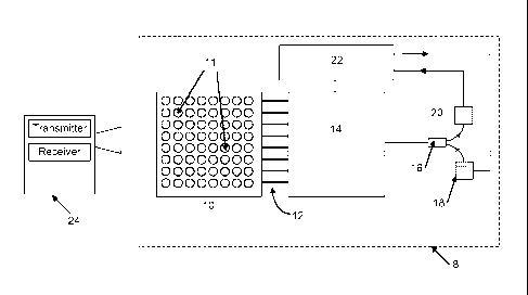
Referring to Figure 1, a target scene generator 8 is shown which
comprises an array 10 of pixel elements 11. There are 8x8 pixel elements as
shown, although more or less pixel elements may be used. A reconfigurable
network of optical waveguides 14 selectively couples a light source 18 to the
pixel elements so that light emitting from the light source can be projected
at a
CA 02744208 2011-05-19
WO 2010/058194 PCT/GB2009/051501
- 10 -
selected pixel element or elements. The light source is typically a source of
laser radiation, hereinafter referred to as a laser.
Network 14 is coupled by a light splitter, or circulator 16 to the laser light
source 18 and a photodetector 20. Detector 20 receives light transmitted from
a
transmitter of a ladar 24 under test and transmits electrical signals to an
electronic controller 22 according to the light received. Controller 22
provides
electrical control signals to laser light source 18 for activating the array
of pixel
elements 10 for projecting a simulated target image to the ladar 24 under
test.
The array 10 can project simulated return signals from one or more
targets within the ladar's field of view, the output of the array providing
the input
to a ladar receiver under test. The ladar may contain a receiver with a single-
element photodetector, for which its transmitter laser would be scanned if
generating an image, or it might contain a staring receiver, with an array of
parallel imaging detector channels.
The array 10 is capable of generating output pulses matching the
pulsewidth of the transmitter, which may be of the order of nanoseconds. The
target scene generator 8 can be adapted to provide variation in the pulse
widths
and pulse shapes that are projected, both to accommodate different types of
transmitters and to allow simulation of pulse-stretching effects such as due
to
target depth.
The timing of the projected pulses is controllable to simulate target range
and range changes. Ideally the range would be controlled to a resolution
comparable to ladar receiver digitisation circuits, which may be a fraction of
a
nanosecond, although a lower resolution corresponding to the transmitter pulse
length may be adequate.
The pixel elements 11 of array 10 are individually controllable by
reconfiguration of the waveguide network to connect any one or more pixels
with the light source. In this way, the array is able to generate any one of
multiple different possible scenes, although only one pixel element 11 may
need
to be illuminated at a time to be able to simulate a spot-scanned ladar (if
the
transmitter beam divergence is not larger than the angle subtended by the
CA 02744208 2011-05-19
WO 2010/058194 PCT/GB2009/051501
- 1 1 -
projector element). The pixel elements are reconfigurable within the
timescales
associated with actual target motion.
The target scene generator is capable of testing ladar of a co-axial type
with a shared transmitter/receiver line of sight or bi-axial with separate
channels
for transmit and receive. The return signals from the projector array may be
triggered by the trigger signal applied to the transmitter of the ladar. Since
co-
axial Ladar may be tested the projector should be able to cope with input
signals as well.
Referring now in more detail to the target scene generator shown in
Figure 1, the array 10 comprises the ends of an array of optical fibres 12.
The
optical fibre ends may incorporate lens elements such as collimating lens
elements (not shown). The other ends of the optical fibres are connected to
the
waveguide network 14 which in this example comprises a switchable fibre
network (note that not all the fibre links are shown). The network 14 contains
optical switches that can reconfigure the internal light paths to determine
which
pixel elements of the generator array are illuminated. In an example of
network
14, (described in more detail below with reference to Figures 2 and 3), the
path
of light through the network can be reconfigured as required to control the
delay
between emission of light from light source 18 and illumination of respective
pixel elements. Suitable switching can for example be achieved in a compact
form using 3-D MEMS optical switches using movable micromirrors. Details of
such suitable multi-channel devices can be found at www.calient.net, and
www.cilimmercilass.com.
In the present arrangement, a switching arrangement, for example a
MEMS system, may be adopted comprising a plurality of moveable elements, or
micro-mirrors, for directing light from the light source from one part of the
waveguide network to another part of the waveguide network so that the
network of waveguides can be reconfigured for directing light from a light
source
to any one or more of a plurality of pixels in the pixel array. For example, a
first
switchable element may be operated to direct light from the light source to
propagate internally along a selected one of a plurality of optical fibres.
Subsequently, light from the first selected optical fibre may be coupled into
a
CA 02744208 2011-05-19
WO 2010/058194 PCT/GB2009/051501
- 12 -
second selected optical fibre by operation of a second switchable element. The
end of a final selected optical fibre may constitute a pixel in the pixel
array. The
reconfigurable arrangement allows light from just a single light source to be
directed to any of the pixel elements by selective switching of the switchable
elements in accordance with a required target image to be displayed to a
ladar.
In known MEMS systems, a MEMS device acts as a projector for
projecting light from multiple light sources in free space to a display screen
for
displaying an image.
Glimmerglass provides optical switch networks of 190 inputs and outputs
and Calient provides switch networks of 320 inputs and outputs. These devices
are switchable in timescales of the order of 10ms, allowing a 100Hz update
rate
on reconfiguring the switch network. The volume associated with the switch
network is in the region of 40 litres for a 320 input/output device, although
such
a network is connected to the target scene generator by a flexible optical
fibre
array 12, as shown in Figure 1. The output fibre array of pixel elements
itself is
small and light and could potentially be used in a dynamic testing
environment.
In addition other optical switch technologies (for example solid state
devices such as thermo-optic switches) are also under development for
telecommunications applications that promise faster switching times and
reduced volumes in the future.
Controller 22 holds an electronic representation of the target to be
imaged, and controls the switchable fibre network 14 to simulate reflections
of
an input light pulse from a target, the reflections comprising output pulses
from
laser 18 transmitted through network 14 and array 10. The controller controls
emission of light from the light source 18.
The controller 22 is programmed prior to testing according to the type of
ladar under test. In spot-scanning ladar, a laser spot is transmitted to scan
a
target scene in a raster scan pattern. The controller 22 reconfigures the
network 14 so that the array 10 projects a returned optical signal in response
to
each laser spot transmitted from the ladar.
CA 02744208 2011-05-19
WO 2010/058194 PCT/GB2009/051501
- 13 -
The output signal from the target scene generator is generated by the
laser source 18. The laser light source may comprise a single fibre-coupled
source which can be any suitable fast-pulse emitter appropriate to the ladar
under test, such as a microchip laser. Alternatively, the light source 18 may
comprise different lasers for emitting light at different wavelengths and with
different pulse shapes, appropriate to the ladar under test, as long as the
wavelengths emitted are within the pass-band of the fibre and can be coupled
into it. The light source 18 may comprise more than one laser for emitting
light
simultaneously within the target scene generator with both laser signals
coupled
together before being injected into the switchable network 14. This would
allow
both OW and pulsed projector emissions to be generated, for example, as might
be required for simulating the effects of a directed energy weapon dazzle
counter measure to the ladar.
In known system, an array of a large numbers of lasers is used for
generating an image. The large number of lasers illuminate a ladar under test
and are in many senses equivalent to the pixel array of the illustrated
embodiment. The present arrangement comprises a reconfigurable network
having an array of passive optical waveguides which can guide light from a
single laser source to any one or more of the plurality of pixels in the pixel
array.
Although more than one laser source may be provided for generating a plurality
of different target images, as the present arrangement may provide just a
single
laser light source it can readily be replaced by or combined with one or more
laser sources having different characteristics (e.g. wavelengths, power levels
or pulse characteristics) in order to simulate different testing environments
and
different ladars. In a preferred arrangement, if more than one laser source is
used for injecting light into the waveguide network, it is injected at a
single
location of the network and controlled to propagate along selected wavegu ides
for illuminating the pixel elements required for generating a desired target
image. Conversely, the known system would require replace of many lasers at
great time and expense.
In other known systems, a plurality of laser sources is fibre-coupled to
respective detector elements of a ladar under test. This known arrangement
CA 02744208 2011-05-19
WO 2010/058194 PCT/GB2009/051501
- 14 -
does not generate a target image but instead provides an input to selected
detector elements in order to simulate returned laser signals from a target.
The
time taken to set up this known system is prohibitive and it can not readily
be
used to test multiple ladars one after another.
For testing co-axial ladar, the light source 18 may comprise a mirror or
retro reflector in order to recreate unusual pulse shapes. This may be of use,
for example, for ladars containing a Doppler measurement element where the
transmitter pulse shape may not be simple and may contain both short-pulse
and long-pulse components. A mirror may be used to reflect the transmitter
pulse shape, combined with a suitable variable and programmable in-line
optical delay to simulate target range. In this case, the in-line delay is
preferably variable from zero to the equivalent maximum engagement range
being simulated.
In order to simulate target range, a delay is required between the target
scene generator receiving light from the ladar and transmitting returned light
to
the ladar. A longer delay equates to a longer range between the ladar and the
target. In a reflective type target scene generator, the generator typically
comprises a light path which provides a time delay equivalent to the sum of
the
range from the ladar to the generator and from the generator to the ladar. The
use of light source 18 in the illustrated target scene generator means that
the
switchable fibre network is not required to comprise delay paths corresponding
to the target range, as this delay can be introduced by controlling the
trigger
timing applied to the light source (i.e. the light source emits light at a
determined
time delay after receiving light from the ladar in order to simulate the time
taken
for light to travel from and to the ladar under test).
The detector 20 is a high band-width photodetector matched to the laser
emitter 18, using either a fused fibre coupler or fibre circulator 16 to join
the
paths. This detector triggers the controller to respond to laser pulses input
to
the projector from the ladar transmitter under test, if using a co-axial
system.
An additional separate photodetector can be used to monitor the output of the
transmitter from a bi-axial ladar (not shown).
CA 02744208 2011-05-19
WO 2010/058194 PCT/GB2009/051501
- 15 -
Flexibility and reconfigurability of the target scene generator 8 is
implemented by the switchable fibre network 14 controlled by controller 22.
The
network 14 may comprise switchable optical fibres arranged in patch-panels
with 64 inputs and outputs controlled by controller 22. Such network devices
are commercially available with opto-mechanical switching and capable of
broadcasting one input signal to any of N outputs.
Although a pixel element array 10 is shown with 8x8 pixel elements, an
array with a greater number of pixel elements could be realised. Such an array
may comprise combinations of the pixel array shown, either cascaded with
single laser source, or in parallel with multiple laser sources.
A switch network that incorporated only the previously referenced
exemplary Glimmerglass or Calient switches would be sufficient to simulate the
return from a spot scanned ladar viewing simple targets without pulse
spreading
where only one element of the projector array needs to be illuminated at any
one time with the controller determining the required delay time on triggering
the
laser emitter. With this approach, a model of the scan pattern utilised by the
ladar transmitter is included in the controller 22.
If more than one pixel element is to be illuminated simultaneously such
as for a staring imaging ladar, or if pulse spreading effects such as target
depth
are to be included, then greater sophistication in the switch network is
required,
as explained in more detail below with reference to Figures 2 and 3, in which
two or more stages of optical switch network are shown.
In the Figure 1 embodiment, the emission of light from light source 18 is
delayed to simulate target range. The examples shown in Figures 2 and 3 can
additionally simulate target depth by introducing a delay between the emission
of light from the light source and the transmission of light from respective
pixel
elements in array 10.
For instance, a target which is a ground vehicle may have a depth of
seven metres. A switching network 14 as shown in Figures 2 and 3 may
include selectable delay paths corresponding to pulse spreading due to target
depth for a spot-scanned system, or variations in range across a scene, for a
CA 02744208 2011-05-19
WO 2010/058194 PCT/GB2009/051501
- 16 -
line-scanned or staring system, if these are greater. In order to simulate the
depth of the ground vehicle where a ladar transmits light to eight locations
on
the ground vehicle at progressively greater depth, a progressively longer
delay
would be required and therefore the optical paths become progressively longer.
Accordingly, the respective optical paths are separated by an optical path
difference in air of lm to simulate a depth of 7m which requires a total
length of
about 36m of fibre, i.e. [arithmetic sum of (k*1m), from k=0 to k=number of
delay settings -1]/(glass refractive index, n=1.5)*2.
In more detail, the optical waveguide network 14 is capable of processing
light emitted from the light source 18 and projected by array 10 for
simulating
multiple targets at different ranges, target depth, and variable attenuation
of
signals due to, for example, changes in range or target surface
characteristics.
The target scene generator shown in part in Figures 2 and 3 has similar
features to those shown in Figure 1, some of which are omitted for brevity.
In Figure 2 the light from light source 18 can be selectively coupled to the
array 10 of pixel elements 11 by optical wave guide network 14. The light from
the light source is passed through three stages in network 14 in order to
simulate different target effects or process the light as required.
The light source 18 may contain one or more lasers connected for
transmission to Network 14, although more than one light source would be
required in the presence of directed energy weapons or countermeasures.
Network 14 comprises a first optical switch unit 28 which transmits light to a
time delay unit 30. The first optical switch unit selects the path through the
delay unit for the appropriate delay in accordance with a control signal
received
from the controller 22. The different delay paths may correspond, for example,
to different lengths of optical fibres.
The output of the time delay unit is then input via a second optical switch
32 unit to a pulse-shaping unit 34. The switch unit 32 selects the appropriate
path for the relevant pulse shaping. Pulse shaping techniques are described in
the applicant/assignees US Patent US 7,068,424 on 'Multiple Pulse Generation,
the contents of which are hereby incorporated.
CA 02744208 2011-05-19
WO 2010/058194 PCT/GB2009/051501
- 17 -
The output of the pulse-shaping unit 34 is then input via a third optical
switch unit 36 to an attenuator unit 38, for selection of the appropriate
degree of
attenuation. The attenuation unit 38 may use, for example, programmable in-
line optical fibre attenuators such as those commercially available from
Anritsu,
Hewlett Packard and JDS Uniphase.
The output of the attenuator unit 38 can then be passed to the
appropriate pixel elements 11 on the array 10, via a fourth optical switching
unit
40 that selects the correct (x,y) co-ordinate for the appropriate pixel
element 11.
Each of the time delay, pulse shaping and attenuation units 30, 34, 38
may comprise a specific component associated with an individual pixel element
11 in the array 10 for processing optical signals transmitted by that pixel
element. Accordingly, for an array comprising NxM pixel elements 11, NxM
components would be required, so that each pixel is capable of being operated
independently. Alternatively, a single such component can be associated with
more than one pixel element 11 such that optical signals transmitted by more
than one pixel element can be processed by shared components. The latter
arrangement is preferable from a cost, size and efficiency perspective.
An example of the optical waveguide network 14 in operation is shown in
Figure 3.
In the functional arrangement shown in Figure 3, the light source 18 is
input to a (1xM) optical switch 42 that is capable of multicast distribution
of the
input optical signal between up to M different output paths. The M different
paths represent up to M pixel elements 11 in the pixel element array 10 that
are
to be illuminated in each image frame. The embodiment in Figure 3 shows
M=4, although this is for example only. More than one laser source may be
required for line-scanning or staring ladars or to compensate if the switching
network requires operation at a relatively slow frame rate.
Only one pixel element per frame may need to be illuminated if the ladar
under test is of the spot-scanned type, in which case M may be 1, if the
controller 22 in Figure 1 is able to reconfigure the switch network 14 within
the
frame interval. Alternatively, if more time is needed to reconfigure the
switch
CA 02744208 2011-05-19
WO 2010/058194 PCT/GB2009/051501
- 18 -
network 14 than the frame interval would allow, multiple paths can be
utilised,
i.e. M>1, with each path then generating the optical signals for one frame of
ladar data. The required update rate for the information in each frame is then
reduced by a factor of (1/M). This approach is applicable to line-scanned and
staring ladar sensors, as well as spot-scanned, where M may be greater than
the number of elements 11 in the pixel element array 10 to be illuminated per
frame.
The optical signal in each of the M paths is then provided to the first
stage of the optical switch network 14, although only one complete path is
shown in Figure 3 for clarity, the remaining paths being indicated by dotted
lines. The first stage of the network in Figure 3 selects the time delay on
the
path, relative to the other M paths, in order to simulate target depth. If a
spot-
scanned ladar is being tested then this stage may not be necessary. A 1xN
optical switch is used to select one of N output paths, each with a different
time
delay. The different time delays are represented in Figure 3 by different
numbers of optical fibre loops 44.
In a line-scanned or staring ladar, the first stage of the optical switch
network is used to simulate multiple targets at multiple ranges during a
single
pulse from the ladar. That is, one or more pixel elements 11 in the array may
simulate a first target at a first range (and first time delay) and one or
more
other pixel elements 11 in the array may simulate a second target at a second
range (and second time delay). Alternatively, different pixel elements 11 in
the
array may simulate return signals from a single target, but from portions of
the
target at different ranges.
The outputs from the first stage are recombined by a path recombination
unit 46 for input to the second stage of the fibre network, which selects the
temporal pulse shape. Pulse shaping may be required to simulate certain
characteristics of a simulated target. For instance, when a target is inclined
to
the line of sight different portions of the target are simultaneously at
different
ranges from the ladar. When such a target is illuminated by a laser beam of
finite extent, the pulse duration is stretched. In addition, the amplitude
(peak
power) of the pulse is decreased, since the pulse energy is constant.
CA 02744208 2011-05-19
WO 2010/058194 PCT/GB2009/051501
- 19 -
In Figure 3, the pulse shaping stage comprises an optical splitter to
distribute the optical signal between different paths with different time
delays,
with optical switches that are opened or closed depending on whether each
path is to contribute to the final pulse shape. As an alternative to an
optical
splitter, an optical switch with multicast capability could be adopted or
multiple
individual switches. The second stage of the network comprises a 1xP splitter
to be used, with P different possible portions of the pulse shape.
Alternatively,
an NxP optical switch could be utilised, which would replace the 1xP optical
splitter 32 and the path recombination unit 46 at the end of the first stage.
The output of the pulse shaping network is the sum of paths with different
delays, depending on how much target depth is present, and consequently how
much pulse stretching is required. If there is no pulse stretching, for
example,
then the signal is sent along a path with no delay, if using a multicast
switch.
Alternatively, only the zero delay path switch is closed, if using a splitter
and
individual switches.
The different portions of the pulse shape at the outputs of the second
stage are recombined by a recombination unit 48, which may be a multiplexor,
for input to the third stage, which comprises a optical attenuator 38, for
example
a programmable optical attenuator. Attenuation of the optical signals allows
simulation of changes in signal amplitude due to changes in range. The output
of the attenuator 38 provides an input to an MxK optical switch 40, where
there
are M inputs and K outputs, with K corresponding to the number of pixel
elements 11 in the pixel element array 10.
The pixel element array 10 shown in Figure 3 may be a portion of a
larger pixel element array, with each portion responsive to a laser source 18
and an optical switch network 14. The MxK optical switch 40 directs M optical
signals with the correct relative time delay, the correct pulse shape and the
correct level of attenuation to the selected (x,y) co-ordinates in the pixel
element
array 10, which provides illumination to the ladar under test.
Larger pixel element array sizes may require more than one switch array
to maintain flexibility. The physical switch volumes involved with this
approach
CA 02744208 2011-05-19
WO 2010/058194 PCT/GB2009/051501
- 20 -
will eventually place limits on the size of the projector array that could
feasibly
be managed, although it is expected that future MEMS optical switches will
incorporate larger numbers of channels in smaller formats.
The volume of the optical switches, optical attenuator, optical fibre, plus
the connectors and couplers (not shown) required to operatively connect all
the
components together, contribute to the total volume of the equipment. Such
components can be located remotely to the pixel element array 10, which would
be the only component mounted in front of the ladar under test.