Note: Descriptions are shown in the official language in which they were submitted.
CA 02744273 2011-05-18
WO 2009/077786 PCT/GB2008/051191
1
IMPROVEMENTS IN OR RELATING TO FLUID JETS
The present invention relates to improvements in or relating to fluid jets and
their
effects and apparatus that can be developed to take advantage of specific
forms of jets
and methods of performing functions using such jets.
It is well known that when sea-going vessels operate in shallow water, the
wash from
the propeller can cause erosion of the bed. Propeller scour, as it is called,
is the result
of shear stresses, and to a lesser extent hydro-dynamic pressures, applied to
the bed by
the flow of water set in motion by the propeller. These forces cause surface
particles
to be dislodged, which then become carried along with the flow; the rate of
erosion
increasing as a higher power of the overlying flow velocity in excess of a
certain
threshold that depends on the bed material. Whilst propeller scour can be
detrimental
in ports, harbours and navigation channels, leading to undermining of
structures and
embankments, as well as unwanted siltation elsewhere, it can equally be
beneficial if
the process can be harnessed and applied in a controlled fashion.
US6125560 discloses a means for controlled application of the wash from a
ducted
propeller, for the purposes of seabed excavation and dispersal of the
excavated
material. No specific mention is made, however, about the nature of the flow
or the
excavation process; although it is envisaged that the main agency for
dispersal of the
material will be tidal currents. W02004/065700 notes that since the propeller
is
located close to the duct outlet, the wash possesses certain flow features
that are
peculiar to propeller-generated flows. These include the fact that the flow is
swirling
(i.e. it has a component of rotation about the flow axis) and it is imbued
with a
number of concentrated vortical structures: including an axial hub vortex and
a helical
pattern of peripheral tip vortices.
The presence of swirl, together with the associated vortical structures, can
enhance the
excavation of seabed sediments by ducted propellers due, in part, to the
unsteady
nature of the flow. It can also enable the ducted propeller flow to be
manipulated to
CA 02744273 2011-05-18
WO 2009/077786 PCT/GB2008/051191
2
enhance particular flow characteristics. W02005/002735 describes a means for
flow
manipulation, which involves expansion of the flow by a diffusing, or flared,
nozzle
attached coaxially to the exit of the propeller duct.
It has been noticed, however, that if the flow from a ducted propeller is
forced to
converge, in a particular way, excavation will takes place: i) over a much
larger area,
ii) at a greatly increased rate, and iii) the excavated material will self-
transport over
long-distances before finally re-depositing. Each of these three attributes
will be
described in more detail below. The present invention is based upon the
recognition
that when all three attributes are operating in unison the ducted propeller
has greatly
increased utility for such applications as dredging, seabed levelling and
underwater
sediment management.
In order to appreciate the functional significance of the particular
modification to a
ducted propeller that produces the aforementioned desired attributes and which
forms
the subject matter of the present invention, it is necessary to have a basic
understanding of propeller flows, particularly those from ducted propellers
operating
under high load. By high load is meant a ducted propeller operating in an
essentially
static mode and at maximum design propeller revs. In marine propulsion
parlance
this is often referred to as the bollard-pull (or maximum static thrust)
condition. Close
similarities thus exist between the ducted propeller of the present invention
and such
marine propulsion devices as: tunnel-thrusters of the type used on ferries and
large
vessels for slow-speed transverse manoeuvring. Similarly, an alternative usage
for the
present ducted propeller is as an axial flow propeller pump: for pumping large
quantities of water at relatively low pressures.
The present invention provides an apparatus comprising a body having a fluid
flow
path defined between a fluid inlet and a fluid outlet and thrust means mounted
within
the fluid flow path to direct, in use, a flow of fluid, along the fluid flow
path; wherein
at least a portion of the fluid flow path comprises a duct and wherein the
thrust means
CA 02744273 2011-05-18
WO 2009/077786 PCT/GB2008/051191
3
comprises a propeller mounted within the duct; characterised in that the
apparatus
further comprises a plate spaced from the fluid inlet defining a space
therebetween;
wherein a plurality of elongate pivotable vanes are positioned in a circular
orientation
in the space, about the axis of the flow path and with their pivoting axes
aligned with
the axis of the flow path; wherein the thrust means is adapted to rotate in a
direction
opposite to the direction of flow of fluid through the vanes into the space.
Preferably, the vanes are arranged in a circle so that their pivotal points
are coincident
with the lip of the fluid inlet and they have a height equal to the space
between the
fluid inlet and the plate; wherein the height to diameter ratio of the vanes
is between
0.4 and 0.6, more preferably about 0.5.
Preferably, the vanes are collectively angled at an angle of between 45 and
75 to the
radius of the circle that defines each pivot point, preferably about 60 .
The above and other aspects of the present invention will now be described in
further
detail, by way of example only, with reference to the accompanying drawings,
in
which:
Figure 1 is a sectional side view through a prior art ducted propeller;
Figure 2 is a bottom view of the apparatus of Figure 1;
Figure 3 illustrates schematically the principal characteristics of the fluid
flow
of the apparatus of Figure 1;
Figure 4 is a perspective view from underneath of an embodiment of an
apparatus in accordance with the present invention; and
Figure 5 is a schematic perspective and side view illustrating impact of the
fluid
flow from the apparatus in Figure 4 upon a surface.
CA 02744273 2011-05-18
WO 2009/077786 PCT/GB2008/051191
4
The general form of the ducted propeller utilised in the present invention is
shown in
sectional view in Figure 1 and is generally similar to that disclosed in
W02004/065700. This features a cylindrical duct (1) of varying diameter, with
a
bellmouth inlet (2), a central coaxial motor (3, shown hatched), which in this
case is
hydraulic, but could also be electric or pneumatic and a propeller (4)
attached directly
to the motor shaft and located close to the outlet end (5) of the duct. The
motor is
attached to the duct by a collar (6) and angled struts (7), which are of
unequal number
to the propeller blades. The duct and motor are shaped such that they create
an
annulus of more or less constant cross-sectional area between the inlet and
outlet ends
of the duct. Propeller (4), shown face-on in Figure 2, is of the Kaplan type,
a design
that features large symmetrical blades (8), typically four in number as shown
here,
whose blade tips (9) conform to the inner circumference (10) of the straight
outlet
section (11) of the duct. The propeller rotates within the duct with a minimal
gap
clearance (12) between the blade tips and the inner wall of the duct. The
downstream
end of the motor (3) is formed into a tapered (rope-guard) extension (13), so
that the
taper angle is continuous with that of the propeller hub (14).
It should be noted that: i) the annular flow through the duct is forced to
converge
before it passes through the plane of the propeller by the combined shape of
the duct
and the motor housing, ii) the hub of the propeller has a diameter, which is
approximately 0.3 times the diameter of the propeller and iii) the propeller
has a
slightly unusual pitch distribution (the blades are over-pitched in the hub
region and
under-pitched towards the tips). The latter is a subtle propeller design
feature,
intended to enhance static thrust that is not evident from either Figure 1 or
Figure 2.
For the purposes of seabed excavation or other applications involving
impingement of
the propeller duct flow against a surface, the duct arrangement shown in
Figure 1
would normally be maintained at a specified distance from, and angle to, the
surface
to be jetted. W02004/04775 discloses a variety of deployment means that can
similarly be used with this invention.
CA 02744273 2011-05-18
WO 2009/077786 PCT/GB2008/051191
Figure 3 shows, in diagrammatic form, the main features of a normal ducted
propeller
outlet flow, which are considered important for an understanding of the
present
invention. This is the outlet flow that would be produced in the absence of
the
aforementioned system of inlet vanes or with the inlet vanes orientated
radially so as
5 to enforce radial inlet flow. The flow (or jet) emerging from the duct has a
diameter
equivalent to that of the duct and this diameter is maintained for some
distance
downstream. The outer envelope of the flow is called the streamtube (15) and
it
separates high velocity duct flow from the still ambient fluid. Inside the
streamtube
the flow has axial as well as tangential (swirl) velocity components. The
swirl
velocity is due to the rotation of the propeller, as indicated by the curved
arrow (16),
and the direction of swirl rotation is the same as that of the propeller.
Under heavily-
loaded operating conditions the swirl flow has an approximately uniform
velocity of
fluid rotation.
The streamtube represents a free shear surface, across which there is a jump
in axial
as well as swirl velocity. Vorticity is associated with shearing between two
fluid
bodies and in the present context it can be thought of as the fluid-equivalent
of roller
bearings - allowing the duct flow to move relative to the still ambient
without
significant friction or exchange of momentum.
In order to appreciate the significance of vorticity, and to better understand
the
features of this invention, the reader is invited to perform a simple
demonstration.
Take a pencil, and place it on the base of the palm of the left hand. Hold it
in place
with the finger tips of the right hand, and then move the right hand forward
(while
keeping the left hand still) so that the base of the palm of the right hand
comes to
coincide with the finger tips of the left hand. In carrying out this action it
will be
noticed that: i) the pencil rotates with a sense of rotation that is anti-
clockwise for a
forward movement of the right hand, and ii) the pencil moves a distance of one
hand
length, while the relative distance of movement of the hands is two hand
lengths.
This demonstration serves to highlight that whatever the relative speed of
movement
of the hands (provided that one hand is kept still), the pencil will always
move at half
CA 02744273 2011-05-18
WO 2009/077786 PCT/GB2008/051191
6
this speed. Thus within a free shear layer, vorticity (the pencil) will always
be
transported at approximately half the relative speed of the adjacent fluid
bodies
(provided that one is static) and the sense of rotation of the vorticity will
be
determined by the relative direction of shear (relative movement of the
hands). Note
that if both hands (fluid bodies) move in opposite directions, the pencil
(vorticity)
may remain static and only rotate.
Since the flow from a ducted propeller possess both axial and swirl momentum
the
vorticity residing within the streamtube will be helical in character. Helical
vorticity
(or helicity) can be thought of as a combination of axial vorticity (which is
associated
with tangential or swirl fluid movement) and azimuthal or ring vorticity
(which is
associated with axial fluid movement). The familiar smoke ring vortex is an
example
of pure azimuthal vorticity, being always associated with axial flow. If the
axial flow
that sustains the smoke ring were also to rotate, the smoke ring would take
the form of
a helix.
The propeller blades, being moving boundary surfaces, are where most of the
vorticity
originates, as indicated diagrammatically in Figure 3. The upper (suction)
surface of
the blades, contribute vorticity mainly to the tip vortices (17), while the
lower
(pressure) surfaces contribute vorticity mainly to the centreline hub vortex
(18). The
inner surface of the duct, being static, behaves rather like the still ambient
fluid.
Helical tip vortices (17) trail from the downstream tips of the propeller
blades, with
their sense of winding being opposite to the direction of rotation of the
propeller. The
axial separation distance (19) between adjacent whorls of the same tip vortex
structure
is a measure of the helical pitch. Note that Figure 3 shows only one propeller
blade
and one tip vortex, although there would be four corresponding to the number
of
propeller blades. The direction of fluid rotation within each tip vortex, as
indicated by
the small curving arrows (20) in Figure 3, reflects the relative sense of
axial shear
across the streamtube surface, as indicated by the paired arrows (21). In
actual fact,
with a ducted propeller of the type shown in Figure 1, the tip vortices would
be
subsumed within the boundary layer flow that develops on the duct wall and is
shed
CA 02744273 2011-05-18
WO 2009/077786 PCT/GB2008/051191
7
from the trailing edge of the duct, so the streamtube (15) takes the form of a
more
evenly distributed sheet of vorticity. Nevertheless the sense of spiralling
and rotation
is the same as indicated in Figure 3.
Vorticity has no capacity for self-transport - just as the pencil only moves
by virtue of
the hand moving. Vorticity is, therefore, transported (advected) by the flow
and for
this reason it is often described as being `frozen' within a flow. However, in
real
fluids with strong vorticity, the vorticity can equally be considered as
driving the
flow, through the concept of vortex singularities acting as momentum sources.
This is
tantamount to saying that the pencil causes the hands to move!
In normal ducted propeller jets the outer stream tube vorticity can be
considered as
driving the whole of the axial flow as well as a component of the azimuthal
(swirl)
flow; specifically the outer part of the swirl flow. The hub vortex vorticity
can be
considered as driving the remainder of the azimuthal (swirl) flow and a
counter
component of the axial flow. What the latter means is that in normal ducted
propeller
jets the centreline part of the jet actually has near zero axial velocity.
Near zero axial
velocity equates to elevated stagnation pressure and it is this hydrodynamic
pressure
force which accounts for static thrust in ducted propellers used for slow-
speed
propulsion.
A feature of normal propeller-generated flows is that at a certain distance
downstream
the vortical structures start to exhibit increasing instability. This is shown
in Figure 3
(in the region marked by A) by spiralling of the hub vortex and increasing
irregularity
of the tip vortices. Eventually, in what is known as the far wake, (in the
region
marked by B in Figure 3) the tip vortex structures break down and the hub
vortex
spiralling becomes very accentuated. This instability, which is associated
with
pressure fluctuations, typically occurs at a lesser distance downstream when
the
propeller is more heavily loaded.
CA 02744273 2011-05-18
WO 2009/077786 PCT/GB2008/051191
8
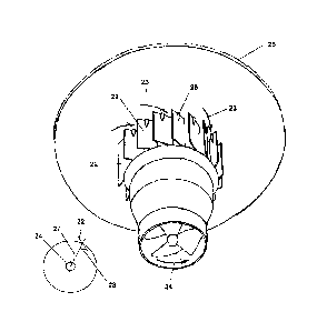
The present invention, which is shown diagrammatically in Figure 4, is
designed to
alter the fluid working environment of the propeller. It does this by means of
a series
of vanes (22) that cause the inlet flow to enter the duct with a component of
pre-swirl.
The orientation of these vanes is such that the pre-swirl has a direction of
fluid
rotation, illustrated by arrows (23), which is opposite to the direction of
rotation of the
propeller, illustrated by arrow (24). The vanes are attached to plate (25) at
pivot
points (26), such that the setting angle can be adjusted, but the vanes can be
locked
into a fixed position when the device is being operated. Plate (25) might, for
instance,
be the top plate of a tank-enclosure such as the embodiment disclosed in
W02004/065700.
The vanes (22) shown in Figure 4 are of relatively crude design and are made
out of
flat plate. Each vane turns the inlet flow slightly and so the simplicity of
design is
offset by having a large number of vanes (in this case 16 number). In
alternative
embodiments (now shown), the vanes are curved to provide a more hydrodynamic
profile. The ratio of the height of the vanes to the diameter as circumscribed
by their
pivot points is important, since it determines (together with the angle of the
vanes) the
amount of swirl introduced into the inlet flow. The larger this ratio the
smaller the
inlet swirl and consequently the more the vanes have to be angled from the
radial to
achieve the optimum amount of swirl. With the set-up shown in Figure 4 the
height to
diameter ratio is approximately 0.5 and the vanes have to be angled at about
60 to the
radial to achieve the desired duct inlet flow.
The effect of the vanes and the resulting inlet pre-swirl is to change the
vorticity
produced by the propeller dramatically; essentially removing the hub vortex
and the
axial vorticity component of the tip vortices. The resulting jet has little or
no swirl,
while the axial flow has uniformly high velocity across the width of the jet.
Static
thrust is thus sacrificed for the sake of increase axial flow production.
Importantly,
the streamtube (tip vortex) vorticity is retained so that the jet remains
columnar and
does not interact with the ambient fluid.
CA 02744273 2011-05-18
WO 2009/077786 PCT/GB2008/051191
9
The change in inlet flow characteristics associated with the inlet vanes
results, in
effect, in a reduction in the angle of attack of the incident flow relative to
the propeller
blades. As a result, the propeller is obliged to operate in a less heavily-
loaded
condition (the propeller absorbs less torque for the same rotation speed), and
so
produces significantly less static thrust. The consequent reduction in outlet
swirl is
the flow manifestation of this change in propeller operating characteristics.
These
effects are particularly evident when a single ducted propeller, with inlet
flow vanes,
is operated in a suspended mode with the jet pointing vertically downwards.
Under
these circumstances the equipment exhibits a higher apparent submerged weight
(due
to the reduced thrust) and a decreased tendency to rotate about the point of
suspension
(decreased torque reaction from the propeller).
With the correct setting angle of the inlet vanes, static thrust (due to
hydrodynamic
pressure) and torque reaction can be all but eliminated. This is the
condition, which in
practice has been found to produce the maximum rate of seabed excavation. An
approximately 600 negative vane setting angle has been found to be the
optimum.
This angle (28) is measured relative to the plane of each vane and a radial
line (27)
passing through the duct centreline and the vane pivot point, as indicated in
the inset
diagram in Figure 4. A negative angle refers to the fact that the vanes are
set to
impart a component of swirl to the inlet flow that is opposite to the
direction of
rotation of the propeller. It will be appreciated that there may be an element
of
adjustment (or tuning) of the inlet vane angle to achieve this optimum
condition.
The general features of the exit flow (i.e. submerged jet) from the propeller
duct of the
present invention are shown diagrammatically in Figure 5. Of key importance
for the
application of the device is the fact that the jet remains essentially
columnar - it does
not spread or otherwise intact with the ambient fluid, as typically occurs
with normal
submerged round jets. This means that the device can be operated at some
distance
(greater than 5 duct diameters) from the surface to be jetted, without
significant loss
of impinging jet momentum. The key to this capability is the retention of the
outer
streamtube envelope, which is a particular feature of propeller-generated
flows.
CA 02744273 2011-05-18
WO 2009/077786 PCT/GB2008/051191
In a number of respects, including its impingement behaviour against a
surface, the
submerged jet from this device resembles a free-fall liquid-into-air jet. To
illustrate
this behaviour the reader is invited to carry out the following simple
experiment.
5 Turn on a kitchen tap slightly so that a thin steady laminar stream of fluid
is produced.
It will be noticed that the fluid stream remains circular and continues to
contract (but
progressively less rapidly) from the tap to the point where it impinges
against the base
of the sink. These characteristics of a free-falling jet result from the fact
that the jet is
driven by gravity rather than by fluid pressure. It will be further noticed
that where
10 the jet strikes the sink base it turns sharply to form a thin wall flow
that runs out
radially across the surface. The thin fluid wall flow has a radial velocity
approximately equal to that of the free-falling jet. That is to say, there is
no loss of
momentum or turbulence-generation where the jet strikes the surface. At a
certain
distance from the point of impingement, which is large compared to the
diameter of
the free-falling jet, the thin-film wall flow suddenly increases in depth and
its velocity
decreases appreciably. This is referred to as a circular hydraulic jump, and
it
represents a transition from super-critical (laminar) flow to sub-critical
(turbulent)
flow.
Impingement of the jet from this invention against a surface is illustrated in
Figure 5.
Just like the free-falling jet, the jet from this device forms a high-velocity
thin-film
wall jet (29) that spreads radially outwards across the surface. Impingement
is
essentially a loss-free (non-turbulent) corner flow phenomenon. Note that in
the
impingement region, the streamtube envelope (15) of the free jet becomes the
upper
free shear surface of the wall jet. The azimuthal vorticity within this vortex
sheet
experiences a stretching due to radial spreading of the thin-film jet; this
increases the
strength of the vorticity and leads to an increase in velocity of the thin-
film jet.
The combination of high-velocity jet impact, and high-velocity outward-
deflected
radial wall jet flow, is what makes this invention so effect for seabed
excavation and
other applications involving surface removal of material. Unlike the free-
falling jet,
CA 02744273 2011-05-18
WO 2009/077786 PCT/GB2008/051191
11
however, which is constrained by gravity to flow downwards, the jet from the
present
device can be made to flow in any direction.
The present jet, like the free-falling jet, is able to extend out radially
across the surface
to many jet diameters before it becomes unstable. Instability in this case
results in the
vorticity finally rolling up to form a large roll vortex (30) as indicated in
Figure 5.
The roll vortex represents the circulation which is conserved through the
jet/impingement/wall-jet regions, indicating that the whole process is
essentially a
laminar (non-turbulent) one. Surface material removed as a result of scouring
by the
thin-film wall jet (29) ultimately ends up in the roll vortex, which entrains
both wall
jet flow and ambient fluid, and grows in size accordingly. Entrainment of
ambient
fluid takes place by a combination of engulfment, mainly on the inner side of
the roll
vortex and by mixing over the surface, which is associated with the formation
of
counter-signed vorticity. The process is indicated, diagrammatically on one
streamline (31), in Figure 5. Some of this counter-signed vorticity also
originates
from frictional boundary layer development at the base of the wall jet. Note
that the
roll vortex represents a `graveyard flow structure' in the sense that it is
where all the
primary vorticity finally breaks down to turbulence as a result of mixing of
jet and
ambient fluid. Turbulent eddies produced in the roll vortex provide a very
effective
means for maintaining eroded sediment particles in suspension.
Note also that the lateral distance at which the roll vortex forms relative to
the
diameter of the impinging jet is dependent on the impinging velocity of the
jet. It is
not particularly sensitive to the distance of the jet nozzle above the jetting
surface.
During seabed excavation operations, it is believed that the roll vortex goes
through
repeated cycles of growth and collapse, for the following reasons. During the
latter
part of the growth stage, the roll vortex is so highly charged with suspended
material
that it becomes gravitationally unstable. This is where gravity acting on the
dense
fluid overcomes circulation, resulting in collapse and the spontaneous
formation of a
dense fluid outflow across the surface. Such a flow is known as a density- or
gravity-
CA 02744273 2011-05-18
WO 2009/077786 PCT/GB2008/051191
12
current, and it provides a very effective means for transporting sediment over
long
distances, even across flat or very gently inclined slopes. For seabed
excavation it
provides the means for long-distance self transport of the excavated material
into
deeper water. Collapse to form a density-current effectively destroys the roll
vortex,
which then starts to reform - hence the cyclic process, which also results in
sequential
waves of density-current flow being produced.
Thus by the simple addition of a set of vanes, of the correct size and
orientation, a
ducted propeller of fairly standard design can be converted into an extremely
effective
and efficient means for seabed excavation and controlled dispersal of the
material.
The fact that the excavated material invariably gravitates into deeper water,
in the
direction of seabed slope, is particularly important for navigation dredging
and bed
levelling operations, where the object is generally to lower the bed to some
specified
minimum level. It is also important from an environmental standpoint since
density-
current transport occurs very close to the bed with very little lofting of
sediment to
higher levels in the water column.
While underwater excavation is the intended primary application of this
invention,
alternative applications include: underwater cleaning, such as biofoul removal
from
ships' hulls, and in a land context, sweeping of leaves and dust. The latter
being an
alternative to conventional brush sweeping or the use of air blowers. Note
that
because leaves and dust are gathered into a roll vortex it is possible to
exercise a much
greater degree of control over their onward transport. By tilting the jet
slightly it is
also possible to displace the material in a preferred direction. For the
latter
application it is envisaged that the simple ducted propeller, with inlet
vanes, might be
attached to the rotating shaft enclosure of a garden strimmer, providing an
alternative
`attachment tool' to the strimmer head.