Note: Descriptions are shown in the official language in which they were submitted.
CA 02744380 2011-05-20
WO 2010/059559 PCT/US2009/064557
METHOD OF REDUCING REDOX RATIO OF MOLTEN GLASS
AND ULTRA-CLEAR GLASS MADE THEREBY
BACKGROUND OF THE INVENTION
1. Field of the Invention
[0001] This invention relates to a method of reducing the redox ratio
(FeO/Fe2O3) of molten glass, and the glass made thereby, and more
particularly, to a method of introducing oxygen into molten glass having a low
iron content to oxidize the iron in the ferrous state (Fe++) to reduce the
redox
ratio.
2. Discussion of the Presently Available technology
[0002] Solar collectors and solar mirrors use solar energy to heat a fluid,
e.g. as disclosed in U.S. Patent Nos. 4,224,927 and 5,253,105, or to convert
solar energy to electrical energy. In general, the solar collectors have a
cover
plate to pass the solar energy, to reduce heat loss due to convection, and to
protect the photovoltaic cells of the electric power generating solar
collectors,
and the solar mirrors have a glass substrate to pass the solar energy to a
reflective coating and reflect the solar energy back through the glass
substrate
to direct the solar energy to a designated area. Of particular interest in the
following discussion are the glass cover plates and the glass substrates.
[0003] As is appreciated by those skilled in the art, the glass cover plates
used for photovoltaic cover plates, and the glass substrates used for solar
mirrors preferably above 380 nanometers ("nm") of the electromagnetic
spectrum have a high transmission, e.g. above 90% in the visible and the
infrared ("IR") range, and a low absorption, e.g. below 2% in the visible and
the
IR ranges. As is appreciated by those skilled in the art, the particular
visible
and IR range of the electromagnetic spectrum, and the peak transmission
varies depending on the semi-conductor material of the photovoltaic cell. For
example and not limiting to the discussion, for a silicon photovoltaic solar
cell,
the preferred visible and IR wavelength range is 380-1200 nm, and the peak
transmission is at about 900 nm.
1
CA 02744380 2011-05-20
WO 2010/059559 PCT/US2009/064557
[0004] Generally, in the manufacture of flat glass, glass batch materials
are melted; the molten glass is fined and homogenized, and the fined
homogenized molten glass is formed into a flat glass ribbon by controllably
decreasing the temperature of the molten glass as it floats on a molten metal
bath. During the fining of the molten glass, gas bubbles are removed from the
molten glass by additions of ingredients to the batch materials, and/or by
moving gases, e.g. carbon monoxide and oxygen through the molten glass,
e.g. see U.S. Patents 2,330,324 and 6,871,514. The batch materials for
making glasses having high transmission, and low absorption, in the visible
and
the IR range of the electromagnetic spectrum have no additions of colorants.
As is appreciated by those skilled in the art, additions of colorants to the
batch
materials have been used to, among other things, reduce the transmission and
increase the absorption in the visible and IR range of the subsequently formed
glass. Glasses having high visible and IR transmission are usually referred to
as low iron glasses. U.S. Patent Nos. 5,030,593; 5,030,594, and 6,962,887
disclose the making of low iron glasses that are almost colorless by
processing
raw glass batch materials that have a very low content of total iron expressed
as Fe203, e.g. less than 0.020 % by weight (hereinafter also referred to as
"wt%" or "wt. %"). Iron contents of less than 0.020 % by weight (200 parts per
million (hereinafter also referred to as "ppm")) in batch materials are
referred to
as tramp iron because the iron is not added to the batch material but is
present
as an impurity in the ingredients of the batch material.
[0005] Even though the iron content is low in low iron glasses, it is also
preferred to reduce the weight percent of ferrous iron (Fe++) in the glass to
maximize the transmission, and minimize the absorption of the glass in the
visible and IR range of the electromagnetic spectrum. As is appreciated by
those skilled in the art, iron in the ferric state is a less powerful colorant
than
iron in the ferrous state and shifts the transmittance spectrum of the glass
toward yellow and away from the usual green-blue effect of the ferrous iron in
glass. Stated another way, increasing iron in the ferric state while
decreasing
iron in the ferrous state, increases the transmission, and decreases the
absorption of the glass in the visible and the IR range. One technique to
reduce the weight percent of ferrous iron in the glass is to include cerium
oxide
2
CA 02744380 2011-05-20
WO 2010/059559 PCT/US2009/064557
in the glass batch materials because cerium oxide in the glass "decolorizes"
the
glass. More particularly, cerium oxide is not a colorant in glass, but is a
powerful oxidizing agent in glass, and its function in decolorized glass is to
oxidize the iron in the ferrous state (Fe++) to iron in the ferric (Fe+++)
state.
Although cerium oxide is useful to decolorize the remaining traces of ferrous
iron, the use of cerium oxide has limitations, e.g. but not limiting to the
discussion, when the glass is to be used as cover plates for electric power
generating solar collectors and as glass substrates for solar mirrors. More
particularly, exposing low iron glass cover plate having cerium oxide to the
sun
has a solarizing effect on the glass, which results from the photo-oxidation
of
Ce+++ to Ce++++ and the photo-reduction of Fe+++ to Fe++. As is appreciated by
those skilled in the art, the solarization effect of cerium and the photo-
reduction
of Fe+++ to Fe++ reduces the transmission, and increases the absorption, of
the
glass in the visible and the IR range of the electromagnetic spectrum, which
reduces the power generation of the solar cells.
[0006] As can now be appreciated, it would be advantageous to provide
a low iron glass that has low levels of iron in the ferrous state (Fe++) and
does
not have the limitation of the photo-reduction of iron in the ferric state
(Fe+++) to
iron in the ferrous state (Fe++)
SUMMARY OF THE INVENTION
[0007] This invention relates to a soda-lime-silica glass, having, among
other things:
Si02 65-75 weight percent
Na20 10-20 weight percent
CaO 5-15 weight percent
MgO 0-5 weight percent
A1203 0-5 weight percent
K20 0-5 weight percent
SO3 0-0.30 weight percent
Total iron as Fe203 0.005-0.120 weight percent
Redox ratio less than 0.550
3
CA 02744380 2011-05-20
WO 2010/059559 PCT/US2009/064557
wherein the glass has less than 0.0025 weight percent of CeO2. The spectral
properties of the glass measured at a thickness 5.5 millimeters include, among
other things, a visible transmission of greater than 85% measured using C.I.E.
standard illuminant "A" with a 20 observer over a wavelength range of 380 to
770 nanometers; a total solar infrared transmittance of greater than 87%
measured over a wavelength range of 775 to 2125 nanometers, and a total
solar energy transmittance of greater than 89% measured over a wavelength
range of 300 to 2500 nanometers, wherein the total solar infrared
transmittance
and the total solar energy transmittance are calculated using Parry Moon air
mass 2.0 direct solar irradiance data and ASTM air mass 1.5 global solar
irradiance data respectively, and integrated using the Rectangular Rule and
Trapezoidal Rule, respectively.
[0008] Further, the invention relates to a method of reducing redox ratio
of soda-lime-silica glass by, among other things, heating a pool of molten
soda-
lime-silica glass having iron in a ferrous state (Fe++) and in a ferric state
(Fe+++), wherein the pool of molten glass is heated with an ignited mixture of
combustion gas and fuel gas emanating from one or more burners, wherein
flow of the combustion gas exceeds the amount of combustion gas required to
ignite the fuel gas such that excess oxygen of the combustion gas oxidizes the
iron in the ferrous state to iron in the ferric state to reduce the redox
ratio.
Optionally oxygen gas can simultaneously be moved through the pool of molten
glass wherein flow of the oxygen gas is in a direction from bottom of the pool
of
molten glass to top of the pool.
[0009] Still further, the invention relates to a method of reducing redox
ratio of soda-lime-silica glass by, among other things, heating a pool of
molten
soda-lime-silica glass in a heating chamber, the pool of molten glass having
iron in a ferrous state (Fe++) and in a ferric state (Fe+++); moving glass
batch
materials onto the pool of molten glass contained in the heating chamber, the
batch materials having iron in the ferrous state (Fe++) and in the ferric
state
(Fe+++); melting the glass batch materials as they float on surface of the
molten
pool of glass; moving oxygen through the pool of molten glass to oxidize the
4
CA 02744380 2011-05-20
WO 2010/059559 PCT/US2009/064557
ferrous iron to the ferric iron to reduce the redox ratio, and forming a glass
ribbon from the pool of molten glass.
BRIEF DESCRIPTION OF THE DRAWINGS
[0010] Fig. 1 is a horizontal section of a glass melting furnace that can
be used in the practice of the invention; Fig. 1A is the melting section of
the
furnace, and Fig. 1 B is the refining and homogenizing section of the
furnace..
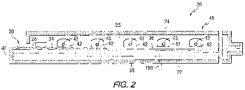
[0011] Fig. 2 is a vertical section of the melting section shown in Fig. 1A.
[0012] Fig. 3 is an elevated side view partially in cross section of a glass
melting and refining apparatus that can be used in the practice of the
invention.
DETAILED DESCRIPTION OF THE INVENTION
[0013] As used herein, spatial or directional terms, such as "inner",
"outer", "left", "right", "up", "down", "horizontal", "vertical", and the
like, relate to
the invention as it is shown in the drawing figures. However, it is to be
understood that the invention can assume various alternative orientations and,
accordingly, such terms are not to be considered as limiting. Further, all
numbers expressing dimensions, physical characteristics, and so forth, used in
the specification and claims are to be understood as being modified in all
instances by the term "about". Accordingly, unless indicated to the contrary,
the numerical values set forth in the following specification and claims can
vary
depending upon the desired property desired and/or sought to be obtained by
the present invention. At the very least, and not as an attempt to limit the
application of the doctrine of equivalents to the scope of the claims, each
numerical parameter should at least be construed in light of the number of
reported significant digits and by applying ordinary rounding techniques.
Moreover, all ranges disclosed herein are to be understood to encompass any
and all subranges subsumed therein. For example, a stated range of "1 to 10"
should be considered to include any and all subranges between and inclusive
of the minimum value of 1 and the maximum value of 10; that is, all subranges
beginning with a minimum value of 1 or more and ending with a maximum
value of 10 or less, e.g., 1 to 6.7, or 3.2 to 8.1, or 5.5 to 10.
CA 02744380 2011-05-20
WO 2010/059559 PCT/US2009/064557
[0014] Before discussing several non-limiting embodiments of the
invention, it is understood that the invention is not limited in its
application to
the details of the particular non-limiting embodiments shown and discussed
herein since the invention is capable of other embodiments. Further, all
documents, such as but not limited to issued patents and published patent
applications, previously discussed, or referred to, and to be discussed or
referred to, herein below are to be considered to be "incorporated by
reference"
in their entirety. Still further, the terminology used herein to discuss the
invention is for the purpose of description and is not of limitation. In
addition,
unless indicated otherwise, in the following discussion like numbers refer to
like
elements.
[0015] Any reference to composition amounts, such as "by weight
percent", "wt%" or "wt. %", "parts per million" and "ppm" are based on the
total
weight of the final glass composition, or the total weight of the mixed
ingredients,
e.g. but not limited to the glass batch materials, which ever the case may be.
The "total iron" content of the glass compositions disclosed herein is
expressed
in terms of Fe203 in accordance with standard analytical practice, regardless
of
the form actually present. Likewise, the amount of iron in the ferrous state
(Fe++)
is reported as FeO, even though it may not actually be present in the glass as
FeO. The proportion of the total iron in the ferrous state is used as a
measure of
the redox state of the glass and is expressed as the ratio FeO/Fe2O3, which is
the weight percent of iron in the ferrous state (expressed as FeO) divided by
the
weight percent of total iron (expressed as Fe203).
[0016] The visible range of the electromagnetic spectrum is 380-780
nanometers (hereinafter also referred to as "nm"), and the infra red
(hereinafter
also referred to as "IR") range of the electromagnetic spectrum is greater
than
780 nm and usually considered to be in the range of 780-10,000 nm. As used
herein, "visible transmittance" or "luminous transmittance" or "LTA" is
measured
using C.I.E. standard illuminant "A" with a 20 observer over the wavelength
range of 380 to 770 nanometers. Glass color, in terms of dominant wavelength
and excitation purity, is measured using C.I.E. standard illuminant "C" with a
20
6
CA 02744380 2011-05-20
WO 2010/059559 PCT/US2009/064557
observer, following the procedures established in ASTM E308-90; "total solar
infrared transmittance" or "TSIR" is measured over the wavelength range of
775 to 2125 nanometers, and "total solar energy transmittance" or "TSET" is
measured over the wavelength range of 300 to 2500 nanometers. The TSIR
transmittance data is calculated using Parry Moon air mass 2.0 direct solar
irradiance data and integrated using the Rectangular Rule, as is known in the
art. The TSET transmittance data is calculated using ASTM air mass 1.5 global
solar irradiance data and integrated using the Trapezoidal Rule, as is known
in
the art. Those skilled in the art will understand that the above spectral
properties, e.g. LTA, infrared transmission, TSIR and TSET are measured at
the actual glass thickness and can be recalculated at any thickness. In the
following discussion the spectral properties of the glass are given for
glasses
having a standard thickness of 5.5 millimeter, even though the actual
thickness
of a measured glass sample is different than the standard thickness.
[0017] The present invention provides a soda-lime-silica glass that is
high in visible light and infrared energy transmittance as measured in a
normal
(i.e. perpendicular) direction to a major surface of the glass sheet, and the
glass of the invention is particularly ideal for, but is not limited to, use
as cover
plates for electric generating solar collectors, and glass substrates for
solar
mirrors. By "high visible light transmittance" is meant measured visible light
transmittance equal to or greater than 85%, such as equal to or greater than
87%, such as equal to or greater than 90%, at 5.5 mm glass thickness. As is
appreciated by those skilled in the art, a glass having a 90% visible light
transmittance at a thickness of 5.5 mm, has a visible light transmission
greater
than 90% at a thickness less than 5.5 mm and has a visible light transmission
less than 90% at a thickness greater than 5.5 mm. By "high infrared energy
transmittance" is meant measured infrared energy transmittance equal to or
greater than 85%, such as equal to or greater than 87%, such as equal to or
greater than 90%, such as equal to or greater than 91 %, at 5.5 mm. As is
appreciated by those skilled in the art, a glass having a 91 % infrared energy
transmittance at a thickness of 5.5 mm, has an infrared energy transmission
greater than 91 % at a thickness less than 5.5 mm and has an infrared visible
light transmission less than 91 % at a thickness greater than 5.5 mm for
glasses
7
CA 02744380 2011-05-20
WO 2010/059559 PCT/US2009/064557
having a thickness less than 5.5 mm.
[0018] The glass of the invention can be made using a conventional non-
vacuum refiner float glass system, e.g. but limited to the type shown in Figs.
1
and 2, or using a vacuum refiner float glass system, e.g. but not limited to
the
type shown in Fig. 3. Other types of conventional non-vacuum systems are
disclosed in U.S. Patent Nos. 4,354,866; 4,466,562 and 4,671,155, and other
types of vacuum refiner float glass system are disclosed in U.S. Patent Nos.
4,792,536 and 5,030,594.
[0019] Referring to Figs.1 and 2, there is shown a conventional
continuously fed, cross-tank fired, glass melting and non-vacuum refining
furnace 20 having an enclosure formed by a bottom 22, roof 24, and sidewalls
26 made of refractory materials. The glass batch materials 28 are introduced
through inlet opening 30 in an extension 32 of the furnace 20 known as the
fill
doghouse in any convenient or usual manner to form a blanket 34 floating on
surface 36 of molten glass 38. Overall progression of the glass as shown in
Figs. 1 A and 1 B is from left to right in the figures, toward entrance end of
a
glass forming chamber 40 of the type used in the art to make float flat glass.
[0020] Flames (not shown) to melt the batch materials 28 and to heat the
molten glass 38 issue from burner ports 42 spaced along the sidewalls 26 (see
Fig. 2) and are directed onto and across the surface 36 of the molten glass
38.
As is known by those skilled in the art, during the first half of a heating
cycle,
the flames issue from a nozzle 43 (see Fig. 2) in each of the ports on one
side
of the tank 20, as the exhaust of the furnace moves through the ports on the
opposite side of the furnace. During the second half of the heating cycle, the
function of the ports are reversed, and the exhaust ports are the firing
ports,
and the firing ports are the exhaust ports. The firing cycle for furnaces of
the
type shown in Figs. 1 and 2 are well known in the art and no further
discussion
is deemed necessary. As can be appreciated by those skilled in the art, the
invention contemplates using a mixture of air and fuel gas, or a mixture of
oxygen and fuel gas, to generate the flames to heat the batch materials and
the
molten glass. For a discussion of using oxygen and fuel gas in the furnace of
8
CA 02744380 2011-05-20
WO 2010/059559 PCT/US2009/064557
the type shown in Fig. 1, reference can be made to U.S. Patent Application
Serial No. 12/031,303 filed February 14, 2008 and titled "Use of Photovoltaics
for Waste Heat Recovery."
[0021] The glass batch materials 28 as they move downstream from the
batch feeding end or doghouse end wall 46 are melted in the melting section 48
of the furnace 20, and the molten glass 38 moves through waist 54 to refining
section 56 of the furnace 20. In the refining section 56, bubbles in the
molten
glass 38 are removed, and the molten glass 38 is mixed or homogenized as the
molten glass passes through the refining section 56. The molten glass 38 is
delivered in any convenient or usual manner from the refining section 56 onto
a
pool of molten metal (not shown) contained in the glass-forming chamber 40.
As the delivered molten glass 38 moves through the glass-forming chamber 40
on the pool of molten metal (not shown), the molten glass is sized and cooled.
A dimensionally stable sized glass ribbon (not shown) moves out of the glass-
forming chamber 40 into an annealing lehr (not shown). Glass making
apparatus of the type shown in Figs. 1 and 2, and of the type discussed above
are well known in the art and no further discussion is deemed necessary.
[0022] Shown in Fig. 3 is continuously fed glass melting and vacuum
refining equipment 78 for melting glass batch materials and refining the
molten
glass. Batch materials 80, preferably in a pulverulent state, are fed into
cavity
82 of a liquefying vessel, e.g. a rotating drum 84. A layer 86 of the batch
material 80 is retained on the interior walls of the vessel 84 aided by the
rotation of the drum and serves as an insulating lining. As the batch material
80
on the surface of the lining 84 is exposed to the heat within the cavity 82,
it
forms a liquefied layer 88 that flows out of a central drain opening 90 at the
bottom 92 of the vessel 84 to a dissolving vessel 94 to complete the
dissolution
of unmelted particles in the liquefied material coming from the vessel 84.
[0023] A valve 96 controls the flow of material from the dissolving vessel
94 into a generally cylindrical vertically upright vessel 98 having an
interior
ceramic refractory lining (not shown) shrouded in a gas-tight, water-cooled
casing 100. A molten stream 102 of refined glass falls freely from the bottom
of
9
CA 02744380 2011-05-20
WO 2010/059559 PCT/US2009/064557
the refining vessel 98 and can be passed to a subsequent stage in the glass
making process as detailed in U.S. Patent No. 4,792,536. For a detailed
discussion on the operation of the equipment 78 shown in Fig. 3 reference can
be made to U.S. Patent No. 4,792,536.
[0024] As is appreciated, the invention is not limited to the process of
and/or equipment for making glass, and any of the glass making processes
and/or equipment known in the art can be used in the practice of the
invention.
[0025] Typically, the glass batch used in the glass making apparatus
shown in Figs. 1 and 2 includes sodium sulfate (salt cake) as a melting and
refining aid in the amounts of about 5 to 15 parts by weight per 1000 parts by
weight of the silica source material (sand), with about 10 parts by weight
considered desirable to assure adequate refining, i.e. removal of bubbles from
the molten glass. The sulfur-containing materials can be added such that the
retained sulfur content e.g., the average amount of SO3 left in the resultant
bulk
glass is less than or equal to 0.2 wt. %, such as less than or equal to 0.15
wt.
%, such as less than or equal to 0.1 wt. %, such as less than or equal to 0.05
wt. %. In one non-limiting embodiment of the invention, the residual sulfur
can
be in the range of 0.005 wt. % to 0.13 wt. %. When operating the glass making
apparatus 78 shown in Fig. 3, it is preferred, but not limiting to the
invention, to
restrict the sodium sulfate to less than two parts by weight per 1000 parts by
weight of the silica source material and to restrict the SO3 to less than 0.02
wt.
%. More particularly, the glass batch materials melted in the glass making
apparatus 78 shown in Fig. 3 are essentially free of sulfur. By "essentially
free
of sulfur" is meant that no intentional addition of sulfur-containing
compounds is
made to the glass batch materials. However, trace amounts of sulfur can be
present in the glass due to impurities in the batch materials or other
sources,
e.g. but not limited to cullet. By "trace amounts of sulfur" is meant sulfur
in the
range of greater than 0 wt. % to 0.03 wt. %. The "sulfur" content of the glass
compositions disclosed herein is expressed in terms of SO3 in accordance with
standard analytical practice, regardless of the form actually present.
[0026] Glass batch materials used for making low iron glass cover plates
CA 02744380 2011-05-20
WO 2010/059559 PCT/US2009/064557
for electric power generating solar collectors, and for making glass
substrates for
solar mirrors preferably provide a glass that has a high measured
transmission,
e.g. greater than 90%, and a high measured IR transmission, e.g. greater than
91 %. In the practice of the invention, iron is not intentionally added to the
batch
materials, and iron present in the molten glass as ferrous iron (Fe++) is
oxidized
to ferric iron (Fe+++) As is appreciated by those skilled in the art and as
discussed above, additions of CeO2 are added to the glass batch materials to
oxidize the ferrous ion (Fe++) to the ferric ion (Fe+++) to increase the
visible and
IR transmission of the glass. It is believed, however, that exposing glass
having
CeO2 to the sun's radiation results in solarization reactions which photo-
oxidizes
Ce+++ to Ce++++ and photo-reduces Fe+++ to Fe++', which results in the
reduction
of visible and IR transmission of the glass. CeO2 in amounts less than 0.0025
wt. % (25 ppm) or less in the glass does not result in objectionable levels of
solarization, e.g. a reduction of less than 0.15% of the measured visible and
IR
transmission after exposure to sunlight for 28 days. CeO2 in amounts equal to,
or greater than 0.0800 wt. % (800 ppm) results in unacceptable levels of
solarization, e.g. a 1.0% reduction in the measured visible and IR
transmission of
the glass after exposure to sunlight for 28 days.
[0027] In view of the forgoing, in the preferred practice of the invention
ingredients that oxidize the ferrous iron Fe++ to the ferric Fe +++ and can be
solarized, e.g. CeO2 are not added to the batch materials, and if present, are
present as tramp materials, such that the glass preferably has equal to or
less
than 0.0025 wt. % (25 ppm) CeO2. Although the invention is directed to low
iron
soda-lime-silica glasses, e.g. soda-lime-silica glasses having equal to or
less
than 0.01 wt. % (100 ppm) total iron expressed as Fe203, the invention is not
limited thereto, and the invention can be practiced to lower the percent by
weight
of the ferrous iron in high iron glasses, e.g. soda-lime-silica glasses having
greater than 0.01 wt. % (100 ppm) total iron expressed as Fe203. Further, the
invention is not limited to glass cover plates for solar collectors, and to
glass
substrates for solar mirrors, and can be used (1) as a glass cover plate, or
glass
substrate for any type of solar cell or solar collector; (2) as residential
and
commercial windows; (3) as windows for any type of vehicle, e.g. land, air,
space, above water, and below water, vehicle; (4) as furniture table tops, and
(5)
11
CA 02744380 2011-05-20
WO 2010/059559 PCT/US2009/064557
combinations thereof.
[0028] Table 1 lists the major constituents and their respective ranges in
weight percent of a non-limiting embodiment of a commercial clear float glass
of the invention that can be used to make cover plates for solar collectors,
glass substrates for solar mirrors, and/or commercial, residential and
appliance
windows.
TABLE 1
CONSTITUENT WEIGHT %
Si02 65-75
Na20 10-20
CaO 5-15
MgO 0-5
A120 0-5
K20 0-5
S03 0-0.30
Total iron as Fe203 greater than 0-0.120
Redox ratio less than 0.350
[0029] Usually cerium is added to the batch materials as hydrated
cerium carbonate (Ce2CO3.3H20) and can be present in the glass as Ce+++
(Ce203) or Ce++++ (CeO2). In one non-limiting embodiment of the invention, no
CeO2 is present in the glass. In another non-limiting embodiment of the
invention CeO2 is present in the glass in amounts equal to or less than 0.0025
wt. %. In still another non-limiting embodiment of the invention, CeO2 can be
present in the glass as a tramp material, e.g. as an impurity in the batch
materials and/or in the glass cullet added to the batch materials to aid in
the
melting of the batch materials. Based on the forgoing CeO2 can be present in
the glass of the invention within the range of 0 to 0.0100 wt. %, preferably
in
the range of 0 to 0.0075 wt. %, more preferably in the range of 0 to 0.0050
wt.
%, and most preferably in the range of 0 to 0.0025 wt. %.
12
CA 02744380 2011-05-20
WO 2010/059559 PCT/US2009/064557
[0030] Clear soda-lime-silica glasses having low amounts of iron have a
substantial absence of color in visible transmittance. In the practice of one
non-
limiting embodiment of the invention, the total iron expressed as Fe203, is
less
than about 0.025 wt. % (250 parts per million), more preferably less than
0.015
wt. % (150 parts per million) and most preferably less than 0.010 wt. % (100
parts per million), and in the preferred practice of the invention the glasses
have
a redox value (FeO/Fe2O3) of less than 0.35, preferably less than 0.25, more
preferably less than 0.20, and most preferably less than 0.150.
[0031] Examples of commercial low iron glass that have high measured
visible and IR transmission are presented in Table 2 below.
TABLE 2
(A) (B)
CONSTITUENT WEIGHT % WEIGHT %
Si02 65-75 65-75
Na20 10-20 10-20
CaO 5-15 5-15
MgO 0-5 0-5
A1203 0-5 0-5
K20 0-5 0-5
SO3 0.12-0.20 0.12-0.20
Total iron as Fe203 0.005-0.025 0.005-0.025
Redox ratio less than 0.250 less than 0.550
CeO2 0.18-0.256 0.02-0.100
[0032] The glasses of Table 2 can be made using the equipment shown in
Figs. 1-3; it should be noted however, that if the equipment shown in Fig. 3
is
used, the SO3 is preferably less than 0.02 wt%.
[0033] In the practice of the invention, oxygen is introduced into the
molten glass to oxidize the ferrous iron (Fe++) to the ferric iron (Fe+++) In
one
non-limiting embodiment of the invention, oxygen is bubbled into the pool of
molten glass; in another non-limiting embodiment of the invention, the ratio
of
13
CA 02744380 2011-05-20
WO 2010/059559 PCT/US2009/064557
oxygen to fuel or firing gas is increased to oxidize the iron in the ferrous
state
(Fe++) to iron in the ferric state (Fe+++) and in still another non-limiting
embodiment of the invention, oxygen is bubbled into the pool of molten glass
and the ratio of oxygen to fuel or firing gas is increased to oxidize the iron
in the
ferrous state (Fe++) to iron in the ferric state (Fe+++) Support for one non-
limiting
embodiment of the invention that oxygen can be used to oxidize the iron in the
ferrous state to iron in the ferric state, and for another non-limiting
embodiment
of the invention that oxygen can be used to replace all or part of the CeO2 to
oxidize the iron in the ferrous state to iron in the ferric state, is provided
by the
following experiment.
[0034] Six lab melts were made of low iron glass of the type sold by PPG
Industries, Inc. under the registered trademark Starphire. Each of the lab
melts
included 1000 grams of Starphire glass cullet. The glass composition of the
cullet was not analyzed; however, the Starphire glass has a glass composition
within the ranges of the ingredients shown in column (B) of Table 2. The
cullet
was contained in 4-inch silica crucibles and melted at a temperature of 2600
degrees F (1427 degrees C). Oxygen gas was introduced into the molten glass
using a porous ceramic tube made by etching the bottom 1 inch (2.54
centimeters) of the closed end of a mullite tube in hydrofluoric acid.
Although
the sizes of the holes were not measured, it is believed the holes had a
diameter of about less than 1 millimeter.
[0035] Sample A was the control sample and no oxygen was introduced
into the molten glass of Sample A. The flow rate of oxygen introduced into the
molten glass of Sample B was 10 cubic centimeters ("CC") per minute for 30
minutes; into the molten glass of Sample C was 20 CC per minute for 30
minutes; into the molten glass of each of Samples D and E was 20 CC per
minute for 60 minutes, and into the molten glass of Sample F was 20 CC per
minute for 120 minutes. Upon conclusion of the introduction of oxygen of the
molten glass of the Samples B-F, it was observed that the ends of the tubes in
the molten glass of Samples C and D were broken. It is believed that the tubes
broke as a result of thermal shock. The molten glass of each of the crucibles
of
Samples A-F was cooled, and the glass analyzed to determine the redox ratio of
14
CA 02744380 2011-05-20
WO 2010/059559 PCT/US2009/064557
Sample A (the control sample) and the redox ratio of the Samples B-F (the
"test
samples"). The FeO, Fe203 and FeO/Fe2O3 (the redox ratio) of the Samples A-F
are shown in Table 3 below.
TABLE 3
COMPONENT SAMPLE
A B C D E F
FeO 0.0044 0.0038 0.0022 0.0043 0.0002 0.0000
Fe203 0.0154 0.0162 0.0172 0.0179 0.0172 0.0176
FeO/Fe2O 0.286 0.235 0.128 0.240 0.012 0.000
[0036] The Samples B-F each had a lower redox value than the redox
value of Sample A indicating that more of the ferrous iron in Samples B-F was
oxidized than in the Sample A. Based on the amount of oxygen added to the
molten glass for sample F and sample C, the efficiency for below Reaction 1
ranged from 0.16 to 0.35%. The efficiency was determined by calculating the
amount of oxygen that reacted with the ferrous iron divided by the total
amount
of oxygen introduced into the molten glass during the lab experiment through
the
porous ceramic tube.
Reaction 1 4FeO + 02 H 2Fe2O3
[0037] As is appreciated by those skilled in the art, the above lab
experiment clearly demonstrates that moving oxygen through molten glass
oxidizes the ferrous iron to the ferric iron and lowers the redox ratio.
[0038] In the practice of one non-limited embodiment of the invention,
the glass batch ingredients selected for making low iron glasses have no
additions of iron, and any iron present in the batch materials is present as
tramp materials. Iron content generally referred to as tramp amounts of iron
are amounts of iron less than 0.025 wt. %. For purposes of the present
invention, batch materials are selected to have an iron content to provide the
glass with a total iron expressed as Fe203 of less than 0.025 wt. % (250 ppm).
As is appreciated by those skilled in the art, batch materials are selected
for
minimal iron contamination, but it would be difficult to reduce the total iron
CA 02744380 2011-05-20
WO 2010/059559 PCT/US2009/064557
content (Fe203) in the glass batch materials to provide a glass having less
than
about 0.005 wt. % (50 ppm) without incurring considerable expense. In the non-
limiting embodiment of the invention under discussion, batch selection
includes
a low iron sand, which can have an iron content of about 0.008 wt. % iron (80
ppm) analyzed as Fe203. Limestone and dolomite, conventional glass batch
materials, are avoided because of their typical iron contamination. Instead,
it is
preferred to use a purer source of calcium such as aragonite, which is a
mineral form of calcium carbonate with only about 0.020 wt. % (200 ppm)
Fe203. Further it is preferred to use low iron dolomite, having an iron
(Fe203)
content of less than about 0.020 wt. % (200 ppm). A preferred alumina source
is aluminum hydrate, with about 0.008 wt. % (80 ppm) Fe203. An example of a
glass batch mixture that can be used to make glasses within the ranges of the
glass of Table 1 is shown in Table 4.
TABLE 4
Batch Constituent Parts by Weight
Low Iron Sand 1000
Soda Ash 322-347.8
Aragonite 160-281
Dolomite 0-179
Aluminum hydrate 0-35.1
Salt Cake 0-15
[0039] As discussed above, in the preferred practice of the invention,
cerium is not added to the batch materials, and preferably, but not limiting
to the
invention, cerium is only present as a tramp material, e.g. less than 0.010
wt. %
(100 ppm).
[0040] The batch materials for the glass making processes shown in
Figs. 1-3 preferably include the ingredients in the range shown on Table 4,
except that the glass making apparatus shown in Fig. 3 is preferably operated
using two parts by weight of sodium sulfate per 1000 parts by weight of the
sand (the silica source material); whereas, it is preferred to operate the
glass
making apparatus of Figs. 1 and 2 using 7 parts by weight of sodium sulfate
per
16
CA 02744380 2011-05-20
WO 2010/059559 PCT/US2009/064557
1000 parts by weight of the silica source material. In the practice of the
invention, the glass batch materials of Table 4 provide glasses having
compositions shown in Table 5 below.
TABLE 5
(A) (B) (C)
Ingredient wt. % wt. % wt. %
Si02 72.65 73.26 72.85
Na20 13.87 15.09 14.04
CaO 10.20 11.03 9.64
MgO 2.94 0.17 3.14
SO3 0.173 0.196 0.169
Fe203 0.0086 0.0087 0.0176
A1203 0.04 0.04 0.04
SrO 0.126 0.206 0.108
[0041] The glass compositions of Table 5 were computer calculated from
the batch formula of Table 4. It should be noted, however, that the glass
composition of the fifth experiment discussed below was selected to be similar
to computer calculated glass composition of Column (A) of Table 5. The
computer program does not provide a redox ratio; however, the redox ratios of
the invention discussed above are applicable for the glass compositions shown
in Table 5. The glasses listed in Table 5 made using the glass making
apparatus of Fig. 3 would have an S03 content less than 0.02 wt. %. As can
be appreciated, the invention is not limited to the glass compositions listed
in
Table 5.
[0042] Other ingredients having a wt. % less than 0.01 wt. % are tramp
materials which are impurities found in the batch materials and can include
Mn02, Zr02, CoO, Se, NiO, Cl, P205, V205, CeO2, Cr203, Li20, K20 and Ti02.
[0043] The following experiments were conducted on a glass production
line having a furnace of the type shown in Figs. 1 and 2 to determine the
effect of
exposing molten glass 38 to controlled amounts of 02 prior to the molten glass
17
CA 02744380 2011-05-20
WO 2010/059559 PCT/US2009/064557
38 moving through the waist 54 of the furnace 20. In one experiment two
oxygen spargers each consisting of a 2 inch (5.08 centimeter ("cm")) diameter,
6
inch (15.2 cm) long porous A1203-ZrO2-SiO2 refractory (tradename Vision
commercially available from ANH Refractories Co.) cylindrical block attached
to
the end of a 1 inch (2.54 centimeter) diameter and 16 feet (4.9 meters) long
water cooled straight metal pipe were located 3 feet (0.9 meters) from the
batch
feeding end 46 of the melter 48 and 4 feet (1.2 meters) from the left wall of
the
furnace, and the second sparger was located 3 feet (0.9 meters) from the batch
feeding end of the melter and 4 feet (1.2 meters) from the right wall of the
furnace. Each of the spargers was spaced 42 inches (1.1 meters) above the
bottom surface of the furnace. Twenty five (25) cubic feet per hour ("CFH") of
oxygen were moved through each of the spargers. It was observed that the
spargers generated gas bubbles that were about 1/8 inch (0.32 centimeter) in
diameter as they burst on the surface of the molten glass.
[0044] The batch composition had ingredients to make glass similar to the
glass listed in column B of Table 5. The batch ingredients initially added to
the
melter did not have any additions of Ce02, the only Ce02 present in the batch
materials were tramp amounts, and the Ce02 present in the glass cullet. Twice
during the glass production run hydrated cerium carbonate was added to the
batch materials. A first sample of the glass was taken before the first
addition of
the hydrated cerium carbonate and was analyzed; the first sample had a redox
ratio of 0.48. Three (3) pounds of hydrated cerium carbonate per 1000 pounds
of sand was added to the batch materials for 12 hours. Forty eight (48) hours
after the first addition of hydrated cerium carbonate, a second sample of the
glass was taken and analyzed; the second sample had a redox ratio of 0.43.
The Ce02 in the glass increased from 0.04 wt. % to 0.06 wt. %. After a period
of
6 days after the first addition, a second addition of hydrated cerium
carbonate
was made. The second addition was 3 pounds of hydrated cerium carbonate
per 1000 pounds of sand for 26 hours. Four (4) days after the second addition,
a
third sample of the glass was taken and analyzed. The third sample of glass
had
a redox ratio of 0.471; contained 0.0102 wt % (102 ppm) Fe203, and 0.04 wt%
(400 ppm) Ce02. The usual level of Ce02 is about 0.07% (700 ppm) and the
usual level of the redox ratio is in the range of about 0.48-0.50. The results
from
18
CA 02744380 2011-05-20
WO 2010/059559 PCT/US2009/064557
the first experiment suggested that the introduction of oxygen gas into the
molten
glass through the two porous refractory spargers can serve as a substitute for
adding CeO2 to oxidize the ferrous iron to the ferric iron, and to lower the
glass
redox ratio by about 0.01 -0.03, in a large commercial glass furnace.
[0045] A second experiment was conducted on a glass production run to
make clear glass having 0.10 wt% Fe203, i.e. high iron glass. In the second
experiment, the sparger positions in relationship to the furnace walls was the
same, however the spargers were spaced 8 inches (20 cm) from the bottom
surface of the furnace. Further, each of the the spargers in the second
experiment was a thicker porous refractory cylindrical block (3 inch (7.6 cm)
diameter compared to only 2 inch (5.08 cm) diameter used in the first
experiment) to increase the useable life of the spargers. The oxygen flow rate
was 20 CFH at 40 PSI through each of the spargers. The average redox ratio of
the glass two weeks before oxygen was flowed through the spargers was 0.338
and the range of the redox ratio was 0.005. The average redox ratio with
oxygen
moving through the spargers was 0.336 and the range of the redox ratio was
0.01. There was no significant change in the mean value of redox ratio, only
an
increase in the variability of the redox value. The conclusion of the second
experiment was that while the glass redox ratio was lowered at least part of
the
time while using the oxygen spargers, the glass redox ratio was not lowered on
a
continuous basis due to non-homogeneous mixing of the molten glass in the
furnace.
[0046] In a third experiment, the production run was making a glass
composition included 0.05 wt% CeO2. In the third experiment, oxygen was
moved through selected bubblers of one row of 19 individual gas bubblers
(water
cooled metal tubes) 150 (see Fig. 1 A) mounted in the base 26 of the furnace
20.
The bubblers extended upward into the molten glass about 24 inches (0.61
meters) from the bottom surface of the furnace and 33 inches (0.84 meters)
below the surface 36 of the molten glass 38. The bubblers 150 were positioned
about 50 feet from the wall 46 of the furnace 20 in the area of the 4th port
42 (see
Fig. 2). The bubblers 150 were spaced about 18 inches (0.46 meters) apart and
span the furnace 20 in a perpendicular fashion to the direction of the molten
19
CA 02744380 2011-05-20
WO 2010/059559 PCT/US2009/064557
glass flow. Initially oxygen was moved through 6 bubblers, and then over the
next three days through 12 of the remaining 13 bubblers; one bubbler did not
function because it was clogged. Although the position of the first six
bubblers
was not recorded, it is believed the six bubblers were the three outer bubbles
on
each end of the row of bubblers. The oxygen flow was initially 5 CFH through
each of the 18 bubblers and was increased after 3 days by 5 CFH, and
increased by 5 CFH once again 4 days after the first increase. The last step
of 5
CFH was reversed because the high rate of oxygen bubbling was entraining and
leaving residual bubbles in the molten glass. It was observed that the
bubblers
generated gas bubbles that were about 6 inches (15.2 cm) in diameter as they
burst on the surface of the molten glass. The glass redox ratio prior to
introducing oxygen gas through the bubblers was 0.45. The glass made with
oxygen moving through the 18 bubblers and after the last step of 5 CFH was
reversed had a redox ratio of 0.41 and an Fe203 of 0.0096 wt. %. The use of
the
oxygen gas in the bubblers lowered the glass redox by 0.04.
[0047] A fourth experiment was conducted on the glass composition of the
third experiment except that the only Ce02 present in the batch materials was
tramp Ce02 in the glass cullet in an amount of 0.04 wt. %. In the fourth
experiment, the bubblers were raised to a position 27 inches (0.69 meters)
from
the level of the molten glass and the oxygen was moved through each of the 18
bubblers 150 at a flow rate of 12.5 CFH. The oxygen gas flow rate was
increased from 12.5 CFH to 17.5 CFH per bubbler, and from 17.5 CFH to 20
CFH per bubbler over the next five days. The rate of oxygen was dropped back
to 17.5 CFH because the high rate of oxygen gas bubbling was entraining and
leaving residual bubbles in the molten glass. A sample of the glass while
bubbling oxygen gas at a flow rate of 17.5 CFH per bubbler had a redox ratio
of
0.467, 0.0092 wt. % (92 ppm) Fe203 and 0.033 wt. % Ce02 (330 ppm). It is
believed that bubbling oxygen gas at a total flow rate of 100 CFH into 7564
cubic
feet of molten glass for 24 hours (2400 CF of oxygen per 7564 cubic feet of
molten glass) is equal to about 0.01 wt. % Ce02 in terms of causing an
equivalent decrease in the glass redox ratio. The efficiency of bubbling with
oxygen gas in the commercial glass furnace was calculated and is about 0.12%,
which is similar to that observed in the laboratory experiment. The efficiency
CA 02744380 2011-05-20
WO 2010/059559 PCT/US2009/064557
was determined by calculating the amount of oxygen that reacted with the
ferrous iron divided by the total amount of oxygen introduced into the molten
glass during the fourth experiment through the 18 bubblers 150.
[0048] From the above experiments it was concluded that the glass redox
ratio can be lowered by introducing oxygen gas into the molten glass as a
substitute for the need to add CeO2 to oxidize the iron in the ferrous state
(Fe++)
to iron in the ferric state (Fe+++) The oxygen gas can be introduced through
either a sparger consisting of a porous refractory block or a water cooled
metal
bubblers. It was observed that the size of the bubbles generated by the oxygen
gas was much smaller using the sparger than with the water cooled bubbler
More particularly, the size of the bubbles from the spargers were similar to
the
bubbles moved through the molten glass in the lab experiment. In the instance
when the glass is made in the glass making apparatus shown in Fig. 3, the
oxygen would be bubbled into the molten glass in the dissolution chamber 94
through bubblers 110 (only one shown in Fig. 3) mounted through the base 112
of the dissolution chamber 94.
[0049] With reference to Fig. 2, in another non-limiting embodiment of the
invention, oxygen to oxidize the ferrous iron (Fe++) to ferric iron (Fe+++) is
provided by increasing the ratio of combustion air, i.e. oxygen gas to the
fuel or
firing gas at the firing ports. The normal firing ratio of combustion air to
fuel gas
is 10.9 as determined by the formula "total combustion air flow rate (the
combustion air to all of the firing ports) divided by total fuel gas flow rate
(fuel
gas to all of the firing ports)." As is appreciated by those skilled in the
art, the
flow rate of combustion air and fuel gas is not evenly distributed to each of
the
firing ports; however, in the practice of the invention the total flow rate of
the
combustion air and the total flow rate of the fuel gas is of interest.
Further, as is
appreciated by those skilled in the art, the combustion gas includes 21 %
oxygen
and the remaining percent mostly nitrogen. Therefore, the normal firing ratio
of
oxygen to fuel gas for combustion air/fuel gas fired furnaces is 2.29 (10.9
total
combustion air/total fuel gas x 0.21 oxygen in combustion air). In the
following
discussion, the "air firing ratio" is determined by the formula "total
combustion air
flow rate (the combustion air to all of the firing ports) divided by total
fuel gas flow
21
CA 02744380 2011-05-20
WO 2010/059559 PCT/US2009/064557
rate (fuel gas to all of the firing ports)" and is normally 10.9. The "oxygen
firing
ratio" for an oxygen/fuel gas fired furnace is determined by the formula
"total
oxygen gas flow rate (the oxygen to all of the firing ports) divided by total
fuel
gas flow rate (fuel gas to all of the firing ports)" and is normally 2.29, and
the
"oxygen firing ratio" for a combustion air/fuel gas firing furnace is
determined by
the formula "total combustion air flow rate times percent of oxygen in the
combustion air divided by total fuel gas flow rate (fuel gas to all of the
firing
ports)" and is normally 2.29. Increasing the air firing ratio to greater than
11.0, or
the oxygen firing ratio to 2.31 by increasing the total combustion air flow
rate or
the total combustion oxygen, respectively, provides excess oxygen to oxidize
the
ferrous iron (Fe++) to ferric iron (Fe+++)
[0050] In a fifth experiment that was conducted on a commercial glass
furnace making low iron glass having a glass composition similar to the
computer calculated glass composition of column A in Table 5. A sample of
glass was taken and analyzed; the glass had a redox ratio of 0.45. During the
fifth experiment, oxygen gas at a flow rate of 3 CFH per bubbler was moved
through the 18 bubblers 150 located in Port 4 of the glass furnace 20. The
batch
materials were changed by using low iron dolomite to replace part of the
aragonite in the glass batch. The dolomite increases the MgO content of the
glass, which increases the durability of the glass as is known in the art. It
is
believed that the addition of dolomite also helps to lower the glass redox,
because the dolomite does not contain high levels of carbon impurities, which
are present in the aragonite and can act as a reducing agent to reduce the
ferric
iron (Fe+++) to the ferrous iron (Fe++)
[0051] Combustion air at each of the 7 ports 42 on each side of the
furnace 20 was increased during their firing cycle by increasing the air
firing ratio
from 12.3 to 13.3 in steps of 0.1-0.4 (increasing the oxygen firing ratio from
2.58
to 2.79 in steps of 0.02-0.084) each over a five day period. About 72 hours
after
the ratio was increased, a sample of glass was taken and analyzed. The redox
ratio of the sample was 0.39. The low iron float glass composition produced is
similar to the computer generated glass composition of Column (A) in Table 5
and contained 0.0084 wt. % (84 ppm) Fe203 and 0.0021 wt. % (21 ppm) Ce02.
22
CA 02744380 2011-05-20
WO 2010/059559 PCT/US2009/064557
The glass had a LTA (visible transmittance value) of 91.3%, a TSIR value of
90.4% and a TSET value of 90.7% at an actual thickness of about 3.2 mm
(0.1254 inches). An LTA value of 91.3%is a very high glass transmittance that
is
useful as a cover plate to protect the photovoltaic cells in electric power
generating solar collectors and as a glass substrate for solar mirrors. It is
concluded from this fifth experiment that the glass redox ratio can be lowered
by
about 0.06 by increasing the air firing ratio (the oxygen firing ratio).
[0052] As is appreciated by those skilled in the art, increasing the oxygen
firing ratio and operating the furnace at elevated temperatures can increase
NOx
emissions. This can be managed by reducing the temperature of the furnace
and/or by appropriate emission control equipment. The invention is not limited
to
operating temperature of the furnace and/or by the use of emission control
systems.
[0053] From the above it can be appreciated that increasing the air firing
ratio (the oxygen firing ratio) provides oxygen to the molten glass to oxidize
the
ferrous iron (Fe++) to ferric iron (Fe+++). As can be appreciated, the
invention is
not limited to any particular ratio value; however, it is preferred to have an
oxygen firing ratio of 2.31 (an air firing ratio of 11.0), more preferred an
oxygen
firing ratio of 2.63 (an air firing ratio of 12.5), and most preferred an
oxygen firing
ratio of 2.71 (an air firing ratio of 12.9). Further as can be appreciated,
bubbling
oxygen through the molten glass provides oxygen to the molten glass to oxidize
the ferrous iron (Fe++) to ferric iron (Fe+++). In one non-limiting embodiment
of
the invention, and as discussed above, 2400 CF per 24 hours of oxygen per
7564 cubic feet of molten glass (0.32 CFper 24 hours per cubic foot of molten
glass) is equal to about 0.01 % CeO2 in terms of causing an equivalent
decrease
in the glass redox ratio. Still further, as can be appreciated, increasing the
air
firing ratio (the oxygen firing ratio) while bubbling oxygen through the
molten
glass increases the amount of oxygen to the molten glass to oxidize the
ferrous
iron (Fe++) to ferric iron (Fe+++) and can be used to avoid excessive
increases of
the air firing ratio (the oxygen firing ratio) thereby reducing environmental
concerns.
23
CA 02744380 2011-05-20
WO 2010/059559 PCT/US2009/064557
[0054] Based on the forgoing, the invention can be practiced to make a
glass for solar control cover plates and for solar mirrors, e.g. low iron
glass
having the components in the range shown in Table 6, and the properties
discussed below.
TABLE 6
COMPONENT RANGE
Si02 65-75 wt. %
Na20 10-20 wt. %
CaO 5-15 wt. %
MgO greater than 0 to 5 wt. %
CeO2 less than 0.0025 wt. %
SO3 0.12-0.2 wt. %
Fe203 (total iron) equal to or less than 0.01 wt. %
Redox ratio less than 0.400, or less than 0.350, or
less than 0.200, or less than 0.150
[0055] The glasses of Table 6 at a glass thickness of 5.5 millimeters have
an LTA equal to or greater than 85%, or equal to or greater than 87%, or equal
to or greater than 90%; a TSIR equal to or greater than 85%, or equal to or
greater than 87%, or equal to or greater than 90%, or equal to or greater than
91 %, and a TSET equal to or greater than 89%, or equal to or greater than
90%,
or equal to or greater than 91 %. The spectral properties of the glass vary as
the
redox ratio and/or the Fe203 (total iron) vary as was discussed above.
[0056] Further, based on the forgoing, the invention can be practiced to
make a glass for commercial and residential buildings, furniture and
appliances,
and for land, above and below water, and aerospace, e.g. high iron glass
having
the components in the range shown in Table 7, and the properties discussed
below.
24
CA 02744380 2011-05-20
WO 2010/059559 PCT/US2009/064557
TABLE 7
COMPONENT RANGE
Si02 65-75 wt. %
Na20 10-20 wt. %
CaO 5-15 wt. %
MgO greater than 0 to 5 wt. %
CeO2 less than 0.080 wt. %, or less than
0.060 wt. %, or less than 0.030 wt. % or
less than 0.020 wt. %, or less than
0.010 wt. %
SO3 0.12-0.2 wt. %
Fe203 (total iron) greater than 0.01 wt. % to 0.12 wt. %
Redox ratio less than 0.550, or less than 0.400, or
less than 0.350, or less than 0.200, or
less than 0.150
[0057] The glasses of Table 7 at a glass thickness of 5.5 millimeters, have
an LTA equal to or greater than 85%, or equal to or greater than 87%, or equal
to or greater than 90%; a TSIR equal to or greater than 85%, or equal to or
greater than 87%, or equal to or greater than 89%, or equal to or greater than
90%, and a TSET equal to or greater than 88%, or equal to or greater than 89%,
or equal to or greater than 90%. The spectral properties of the glass vary as
the
redox ratio and/or the Fe203 (total iron) vary as was discussed above.
[0058] The above glasses are preferably, but not limited to the invention,
made in glass making equipment similar to, but not limited to the type shown
in
Figs. 1 and 2. The above glass can be made in glass making equipment
having a vacuum refiner, e.g. similar to, but not limited to the type shown in
Fig.
3 by reducing the SO3 to less than 0.010 wt% as discussed above.
[0059] It will be readily appreciated by those skilled in the art that
modifications can be made to the invention without departing from the concepts
disclosed in the foregoing description. Accordingly, the particular
embodiments
described in detail herein are illustrative only and are not limiting to the
scope
CA 02744380 2011-05-20
WO 2010/059559 PCT/US2009/064557
of the invention, which is to be given the full breadth of the appended claims
and any and all equivalents thereof.
26