Note: Descriptions are shown in the official language in which they were submitted.
= CA 2744429 2017-02-27
1
"Converter and method for converting an audio signal"
The invention relates to a method for simplifying a model of an
acoustic environment, wherein said model comprises a set of transfer
functions, each transfer function corresponding to a set of sound
propagation paths between a sound emitting position and a sound
receiving position in said acoustic environment.
Such a model is known from "An example of adding spatial
impression to recorded music: signal convolution with binaural impulse
responses", Angelo Farina, Dipartimento I ngegneria Industriale University
di Parma, Proc. of International Conference "Acoustics and recovery of
spaces for music", Ferrara 27-28 October 1993, where an acoustic
environment is simulated in a converter by convolving audio signals with
the transfer functions forming this model of an acoustical environment.
For each of the N channels a set of convolutions is established to
calculate the reverberation for each of the M channels such that the audio
when played back through M channels is perceived as it was recorded in
the modelled acoustical environment.
"EARS Auralization Software" by Ahnert W et al, Journal of the
Audio Engineering Society, New York, NY, USA, vol. 41, no. 11, 1
November 1993, pages 894 to 904, discloses an electronically auralized
room simulation (EARS) for use in conjunction with electronic-acoustic
simulator for engineers (EASE). From a room simulation in EASE 2.0, a
simulated monaural room impulse response is created complete with
directivity information, angles of incidence, The response can be stored in
EASE post-processing files and convolved with outer ear transfer
functions to derive a binaural auralization as a function of the selected
listening poition in the room and the head orientation of the simulated
listener.
"Perceptual Audio Rendering of Complex Virtual Environments" by
Tsingos N et al, ACM Transactions on Graphics, ACM TUS LNKD-D01:
10.1145.1015706.1015710, vol. 23, no, 3, 1 August 2004, pages 249 to
CA 2744429 2017-02-27
2
258 discloses a real-time 3D audio rendering pipeline for complex virtual
scenes containing hundreds of moving sound sources. More than ten
times the number of sources available on consumer 3D audio hardware
can be handled due to auditory culling and spatial level- of-detail with
minimal decrease in audio quality. The method described performs well
for both indoor and outdoor environments and leverages the limited
capabilities of audio hardware for many applications, including interactive
architectural acoustic simulations and automatic 3D voice management
for video games. Inaudible sources are dynamically eliminated and the
remaining audible sources are grouped into a number of clusters. Each
cluster is represented by one impostor sound source positioned using
perceptual criterion. Spatial audio processing is then performed on only
the impostor sound sources thereby reducing computational cost. Limited
degradation in audio quality and localization impairment is obtained which
does not vary significantly with the cluster.
Nevertheless, a disadvantage of such models is that to achieve
this expansion of the sound image to match the modelled acoustical
environment, complex transfer functions representing a large number of
sound propagation paths must be processed for each reverberation,
resulting in high processing power and memory requirements for the
converter. It is an objective of the present invention to provide a method
that reduces the processing power and memory required for simulating
the modelled acoustic environment, yet still allow the resulting M channel
audio signal to sound as if it were recorded in the modelled acoustical
environment.
In accordance with an aspect of the invention, there is provided a
method for simplifying a model of an acoustic environment, wherein said
model comprises a set of transfer functions, each transfer function
corresponding to the sound propagation from a sound emitting position to
a sound receiving position in said acoustic environment, the method
comprising, for each transfer function, the step of:
CA 2744429 2017-02-27
3
- calculating a first simulated reverberation of a first stimulus emitted at
said sound emitting position as received at said sound receiving position
by applying said transfer function to said first stimulus;
characterised in that the method further comprises the steps of:
- selecting a subset of a set of local maxima in a first intensity envelope of
the first simulated reverberation; and
- calculating a simplified transfer function which, applied to said first
stimulus, provides a second simulated reverberation with a second
intensity envelope matching said selected subset of local maxima of the
first simulated reverberation.
The local maxima in the intensity envelope represent significant
reverberation components, corresponding to predominant propagation
paths in the modelled acoustic environment. Selecting a subset of these
local maxima allows their match with a simplified transfer function, which
can then be used to simulate the acoustic environment with reduced
processing and memory requirements without a perceived reduction of
the sound image quality.
Advantageously, the selected number of local maxima does not
exceed a predetermined maximum. The maximum size and/or complexity
of the transfer function is thus limited in advance, defining the processing
and memory requirements that will be necessary to handle the simplified
acoustic environment model.
Advantageously, said selected subset of local maxima are
selected from among those above a time-intensity attenuation function.
By selecting such a subset of highest reflections, which show up
as peaks in the intensity envelope of the reverberation above a time-
intensity attenuation function, the most perceptible components are
maintained and perceptible difference to the measured impulse response
is kept at a minimum.
More preferably, said time-intensity attenuation function may be an
exponential attenuation function. The resulting simulated reverberation
CA 2744429 2017-02-27
4
cannot be distinguished by the human ear from a version where all
reverberation components are included, yet the exclusion of
reverberation components below said exponential time-intensity
attenuation function substantially reduces the processing requirements
and complexity.
Preferably, said simplified transfer function may be applied by
convolution with said first stimulus. This provides a particularly faithful
simulated reverberation.
In an alternative method producing an even simpler model of an
acoustic environment, each simplified transfer function is expressed as a
combination of a signal delay and a signal attenuation for each selected
local maximum. In this case, the simulation can be carried out by
applying these transfer functions to the audio signals in comparatively
simple time domain operations, rather than by convolution.
The present invention also relates to a method for converting a
first audio stream comprising N input channels into a second audio
stream comprising M output channels, comprising the steps of, for each
input and output channel:
selecting, in a model of an M-channel acoustic environment
simplified using the abovementioned method, a simplified transfer
function associated with said input channel and output channel;
processing at least part of an input signal from said input channel
by applying said selected simplified transfer function so as to generate at
least part of an output signal for said output channel.
It is thus possible, through the use of the simplified model, to
simulate how the sound would be perceived in the modelled acoustic
environment.
Preferably, M>N. This would thus enable the conversion of a first
audio stream into a second audio stream with a higher number of
channels. However, in alternative embodiments, M may also be lower or
equal to N.
CA 2744429 2017-02-27
In a further embodiment of the method the selected subsets of
local maxima are different for at least two of the M audio channels.
By purposely introducing differences in the simplified transfer
functions of two channels it is avoided that the same signals are
5 calculated for
the two audio channels. Having two sources emit the same
signal in a room will cause the system (room, loudspeakers and sound) to
act as a comb filter causing uneven perception of the two channels
throughout the room. Comb filtering happens if correlated signals come
from different speakers.
To avoid this, the selection of local maxima in the envelope is
purposely treated differently for the two channels, effectively causing a
decoupling of the two channels.
The method allows, using two transfer functions, to artificially
change a mono signal into a stereo signal by simulating the signal paths
from a single source to two receiving points in a room. The two transfer
functions are subsequently modified in order to select a different set of
local maxima.
In a further embodiment of the method the selected sets of
reflections are different for all M channels.
For a multi channel system it is advantageous to ensure that all M
channels are decoupled, to prevent the system to act as a comb filter
causing uneven perception of the two channels throughout the room.
Although the invention would normally be used to change a multi
channel signal into another multi channel signal having even more
channels, for instance converting a 2D audio signal into a 3D audio signal
by calculating additional channels representing an additional layer of
elevated speakers, in its extreme the invention can be used to convert a
mono signal into a 3D signal by using a multitude of simplified transfer
functions, one for each source speaker location combination and by
ensuring a decorrelation of the M channels that the subset of selected
local maxima are different for each of the M channels.
CA 2744429 2017-02-27
6
It is to be noted that these steps could also be used independently
of other steps and/or features of the present invention, 5 including the
selection of a subset of local maxima.
In a particular embodiment of the invention, the output signal
comprises an early part and a late part.
Such a late part normally tends to have few pronounced peaks
associated with particular reflections. Consequently, the simplified
transfer function may be used to generate only the early part, while the
late part may be generated using other approaches, for instance a
conventional approach as known from the abovementioned prior art, or
an algorithmic reverberation method.
The early part tends to have several pronounced peaks
representing dominant reflections where the method of the present
invention allows a removal of the non-dominant reverberation
components, thus reducing processing requirements complexity.
How the output signal is divided into said early and late parts may
be determined according to sound type.
Different kinds of sounds have different divisions between the
early part having several dominant local maxima and the late part having
few or no dominant local maxima.
To reduce the processing requirements the division between early
and late part can be adjusted to optimally apply the appropriate method
to the appropriate part.
The late part of the reverberation can be advantageously removed,
for instance for news reading.
A converter as claimed is advantageously used in an audio device.
The audio device can convert for instance a 2 dimensional sound into a 3
dimensional sound having more channels than the 2 dimensional sound.
This allows the converter to create a 3 dimensional impression from input
channels that do not contain information about the third dimension.
CA 2744429 2017-05-19
7
Such an audio device comprising a converter as claimed may
advantageously be in a motor vehicle.
The acoustic environment in a motor vehicle is often less than
optimal and different from the acoustic environment in which many audio
recordings are made.
The reverberation can be adjusted using the method and converter
of the present invention allowing optimal reproduction of the sound in the
motor vehicle's acoustical environment.
The invention will now be described based on figures showing the
best mode for carrying out the invention.
Figure 1 shows a room with a measurement set up for
characterizing the room.
Figure 2 shows an intensity envelope of a measured impulse
response showing the reverberation at the measurement position in the
room.
Figure 3 shows an intensity envelope of a simulated impulse
response obtained using a model of the room.
Figure 4 shows the intensity envelopes of both the measured
impulse response and the simulated impulse response.
Figure 5 shows the intensity envelope of the simulated impulse
response after setting some components to zero, leaving only a
predetermined number of highest reflections in the reverberation.
Figure 6 shows a converter for converting N audio channels to M
audio channels using a room model.
Figure 7 shows a measured impulse response.
Figure 8 shows a simulated early part.
Figure 9 shows a simulated late part.
Figure 10 shows the selection of peaks to avoid comb filter effect.
Figure 11 shows two channels where the selection of peaks were
chosen to avoid comb filter effect.
CA 2744429 2017-05-19
7a
Although the description refers to a convolution as a way to
calculate the impulse response from an impulse excitation, or the M audio
channels from the N audio input channels, the same can be achieved by
= CA 2744429 2017-02-27
8
simply applying delay and appropriate attenuation for each relevant direct
or indirect (reflection) path to be simulated. This is a well-known
alternative to using a convolution as found in student text books and is
thus not described in detail.
Figure 1 shows a room with a measurement setup for
characterizing the room.
In an acoustical environment 1, for instance a room, an excitation
source 2, for instance a loudspeaker, is positioned at a sound emitting
position. At a sound receiving position a measuring device 3 is placed to
capture the room's response to the stimulus by the excitation source 2.
In a preferred embodiment, the stimulus can be a Time Stretched
Pulse. This is basically an exponential sine sweep, which provides
several advantages over the older MLS (Maximum Length Sequence)
method. One technique for obtaining higher S/N ratios involves recording
multiple TSPs and then averaging; ambient noise and self noise of the
equipment reduces 3 dB for any doubling of the number of recordings.
However, a remaining problem of this technique is that speaker-induced
distortion will not disappear.
Instead it is preferred to use a TSP wherein sweep length will be
approximately 10 times as long as the estimated reverberation time of the
measured room, typically resulting in a length of 15-80 s. This presumes
measuring 10 octaves from start to stop frequency. The sweeps utilized
should also be faded in and out to avoid artefacts. Another factor with
direct influence on the signal/noise ratio is loudspeaker power compared
to the background noise level. It is recommended to use a calibration of
85 dBa SPL at 2m distance by playing a -20 dbFS bandlimited (500-2000
Hz) signal. The sweep goes out 14 dB louder at -6dBFS.
Such an impulse is thus provided via the excitation source 2 and
sound waves travel along various paths, in figure 1 a first path 4 and a
second path 5. Since the first path 4 and the second path 5 have different
= CA 2744429 2017-02-27
9
length the sound waves will arrive at different times at the measurement
device 3, resulting in a reverberation being captured.
The reverberation is different for different measurement and
excitation positions and based on measured reverberations a model of a
room can be established. This method is widely known and can be found
in "An Optimised Method for Capturing Multidimensional "Acoustic
Fingerprints", by Ralph Kessler, Audio Engineering Society, Convention
Paper, Presented at the 118th Convention, 2005 May 28-31 Barcelona,
Spain, and in publications by Prof. Angelo Farina of Italy.
By constructing a transfer function of which the convolution with an
impulse stimulus results in a simulated impulse response having a
reverberation with an intensity envelope that closely matches that of the
reverberation of the measured impulse response, the model of the room
can be constructed as a set of such transfer functions corresponding to a
set of sound emitting positions and sound receiving positions.
To create M audio channels the N input audio channels are
convolved with the set of transfer functions, resulting in M audio channels
having a sound image that resembles the modelled room.
Figure 2 shows a measured impulse response showing the
reverberation at the measurement position in the room.
The intensity envelope 20 of the measured impulse response as a
function of time is shown, on a logarithmic-linear graph, in figure 2 and
comprises several local maxima 21, 22, 23, 24, 25 corresponding to
multiple propagation paths in the room.
Depending on the characteristics of the room the reflections cause
different amounts of delay and attenuation. The peaks 21, 22, 23, 24, 25
in the envelope 20 consequently have different positions and different
amplitudes.
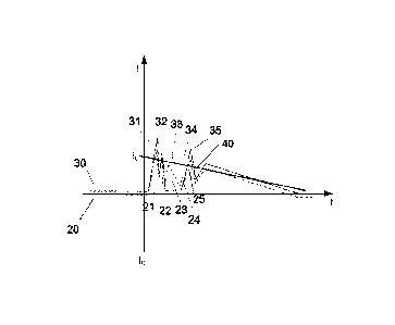
Figure 3 shows a simulated impulse response obtained using the
abovementioned model of the room.
= CA 2744429 2017-02-27
The intensity envelope 30 of the simulated impulse response is
shown in figure 3 and comprises several local maxima 31, 32, 33, 34, 35
that correspond to multiple propagation paths in the modelled room.
Depending on the modelled characteristics of the room different
5 amounts of delay and attenuation are incorporated into the transfer
function. By calculating the convolution between an impulse excitation
and the transfer function the local maxima 21, 22, 23, 24, 25 in the
envelope 30 are obtained and are positioned at the appropriate positions
in the reverberation and having different amplitudes, matching the
10 measured impulse response as close as possible.
Figure 4 shows both the measured impulse response and the
modelled impulse response.
The intensity envelope 20 of the measured impulse response and
the envelope 30 of the calculated impulse response are overlapped for
comparison and as can be seen, in this example a good match between
the intensity envelopes 20, 30 has been achieved.
For instance the first local maximum or peak 31 in the calculated
envelope 30 corresponds well to the first peak 21 of the measured
envelope 20, showing that the transfer function matches the modelled
room quite well.
Figure 5 shows the modelled impulse response after setting some
components to zero, leaving only a predetermined number of dominant
propagation paths in the reverberation.
In the present invention, in order to reduce the complexity of the
convolution the transfer function is simplified. This simplification is
verified
by calculating the impulse response using the simplified transfer function
and checking whether the resulting impulse response still matches the
measured impulse response satisfactorily.
The criterion for checking the simplified transfer function is that a
selected subset of the set of local maxima of the intensity envelope of the
= CA 2744429 2017-02-27
11
measured impulse response is still maintained in the intensity envelope of
the simulated impulse response.
This means that some local maxima can be removed through
modifying, i.e. simplifying, the transfer function. This is shown in 5 figure
5 in that the first peak 31, second peak 32 and fifth peak 35 are still
present in the intensity envelope 30 of the simulated impulse response,
while the third peak 33 and the fourth peak 34 are no longer present.
Figure 5 shows the intensity envelope 20 of the measured impulse
response for ease of comparison.
In a preferred embodiment of the invention, the number of the
selected subset of local maxima 31, 32 and 35 is not higher than a
predetermined number, for instance, in the illustrated example, not higher
than three. This limits in advance the complexity of the simplified transfer
function. Preferably, this selection is carried out by fitting, to the
intensity
envelope 20, a time-intensity attenuation function 40, as illustrated in Fig.
5, that undercuts the predetermined maximum number of local maxima to
be selected, and selecting the local maxima reaching above it, which will
be those more clearly perceived by the human ear. In particular, the time-
intensity attenuation function may be, as shown, an exponential function
according to the equation t(t) =to -e(") , wherein 1(t) is the intensity in
function of time, lo the initial intensity, and to the initial time.
In a particular embodiment, the simplified transfer function may be
expressed as a signal delay and a signal attenuation for each selected
local maximum. The calculation of the impulse response will thus be
possible in a comparatively simple time domain operation, rather than by
convolution.
Figure 6 shows a converter for converting N audio channels to M
audio channels using a room model.
The converter 60 has input channels 64 connected to a processor
61 that can calculate multiple reverberations for various combinations of
= CA 2744429 2017-02-27
12
input channel and output channel. The output signals of the processor 61
are provided to output channels 65.
The transfer functions or parameters for the transfer
functions to be used by the processor 61 are provided via a model input
block which is arranged to receive information about the model or transfer
functions from the parameter input 66.
In an embodiment of the present invention, said processor
calculates, for each input and output channel combination, a convolution
of the input signal with the corresponding simplified transfer function.
In another embodiment of the present invention, if the
simplified transfer function is expressed as a combination of a signal
delay and a signal attenuation for each selected local maximum, these
are applied in time domain operations to the input signal.
A converter for separately processing the early part and the
late part of the reverberation has input channels connected to a divider
for dividing the input signals. The processor that can calculate multiple
reverberations for various combinations of input channel and output
channel so as to generate the early part of output signals. The late part is
either not generated at all or generated by a separate processor also
connected to the divider where the late part is for instance generated in a
conventional manner, such as algorithmic reverberation.
The output channels are provided by the processors to a
combiner where the resulting early and late parts for each channel are
combined into a single output signal to be provided to the outputs.
The transfer functions or parameters for the transfer
functions to be used by the processor are provided via a model input
block which is arranged to receive information about the model or transfer
functions from the parameter input.
Figure 7 shows an audio device comprising the converter.
The audio device 80 comprises the converter 60, of figure 6
or a converter for separately processing the early and late part of the
CA 2744429 2017-02-27
13
reverberation. The audio device receives N input channels, for instance
from an optical disc 81 or a transmission channel (not shown). The N
input channels are provided to the converter 60 to be converted to M
channels. For this the converter needs information about the transfer
functions to be used. This information can be embedded in the converter
60 or in the audio device 80, or can be received from an external source.
Shown in figure 7 is the situation where the information is retrieved from
the optical disc. In such a case the optical disc can comprise both the
input channels as the room model information.
Figure 8 shows the measured impulse response comprising
an early part and a late part. In the illustrated embodiment, the early part
and the late part are contiguous, but in alternative embodiments they may
also be overlapping or spaced apart.
As disclosed above, the processing of the early part and the
late part of the reverberation can be divided and treated separately.
The intensity envelope of the reverberation 20 of figure 2 is
shown again in figure 8 but now with the vertical dotted line indicating the
dividing point between the early part 21, 22, 23, 24, 25 and the late part
91. The dividing point is not fixed in time but is determined based on the
type of sound (for instance voice, classic, jazz, pop etc) or the type of
acoustical environment modelled. In the case of figure 8 the dividing point
is chosen to be between the early section having peaks resulting from
distinct dominant reflections of a relatively high amplitude, and the late
part 91 having a relatively uniform decaying envelope shape without
dominant peaks. As is clear from the description, the invention can
advantageously be used on the early part 21, 22, 23, 24, 25 with its
peaks. The late part 91 can be processed using methods and means
known from the prior art or can be ignored all together.
Figure 9 shows the simulated early part.
The simulated early part 100 of the impulse response
comprises only the dominant peaks 31, 32, 33, 34, 35 as selected by
CA 2744429 2017-02-27
14
using the modelling method of the present invention, equivalently to
figure 5 but with the late part removed before applying the method of the
present invention.
This results in the late part 101 of the simulated
reverberation to be set to zero.
Figure 10 shows the simulated late part.
The modelled late part 110 of the impulse response lacks
the dominant peaks 31, 32, 33, 34, 35 of the early part as the early part
was removed before the processing, but includes the late part 111.
Figure 11 shows two channels 120, 121 where the selection
of peaks for use in the simplified transfer function of the model were
chosen to be different so as to avoid a comb filter effect when played
back in a room. For ease of explanation two identical impulse responses
120, 121 are shown, while in reality the impulse responses will slightly
differ for each channel.
In the first modelled impulse response 120 the second peak
32 has been omitted, while in the second modelled impulse response 121
the fourth peak 34 has been omitted.
Although the present invention has been described with
reference to specific exemplary embodiments, it will be evident that
various modifications and changes may be made to these embodiments
without departing from the broader scope of the invention as set forth in
the claims. For example, although in the present description the signal
processing has been described as if it was performed analogously, all the
signal processing steps of the present invention can advantageously be
performed by digital means, through digital time sampling. Accordingly,
the description and drawings are to be regarded in an illustrative sense
rather than a restrictive sense.