Note: Descriptions are shown in the official language in which they were submitted.
CA 02744749 2011-06-30
2011EM188-CA
BASAL PLANER GRAVITY DRAINAGE
FIELD
[0001] The present
techniques relate to the use of steamflooding to recover
hydrocarbons.
Specifically, techniques are disclosed for creating fluid
communications between spaced horizontal wells at different levels in a
reservoir.
BACKGROUND
[0002] This
section is intended to introduce various aspects of the art, which may
be associated with exemplary embodiments of the present techniques. This
discussion is believed to assist in providing a framework to facilitate a
better
understanding of particular aspects of the present techniques. Accordingly, it
should
be understood that this section should be read in this light, and not
necessarily as
admissions of prior art.
[0003] Modern
society is greatly dependant on the use of hydrocarbons for fuels
and chemical feedstocks. However, easily harvested sources of hydrocarbon are
dwindling, leaving less accessible sources to satisfy future energy needs. As
the
costs of hydrocarbons increase, these less accessible sources become more
economically attractive. For
example, the harvesting of oil sands to remove
hydrocarbons has become more extensive as it has become more economical. The
hydrocarbons harvested from these reservoirs may have relatively high
viscosities,
for example, ranging from 8 API, or lower, up to 20 API, or higher.
Accordingly, the
hydrocarbons may include heavy oils, bitumen, or other carbonaceous materials,
collectively referred to herein as "heavy oil," which are difficult to recover
using
standard techniques.
[0004] Several
methods have been developed to remove hydrocarbons from oil
sands. For example, strip or surface mining may be performed to access the oil
sands, which can then be treated with hot water or steam to extract the oil.
However, deeper formations may not be accessible using a strip mining
approach.
For these formations, a well can be drilled to the reservoir and steam, hot
air,
solvents, or combinations thereof, can be injected to release the
hydrocarbons. The
released hydrocarbons may then be collected by the injection well or by other
wells
and brought to the surface.
- 1 -
CA 02744749 2011-06-30
2011E M188-CA
[0005] A number of techniques have been developed for harvesting heavy oil
from subsurface formations using thermal recovery techniques. Thermal recovery
operations are used around the world to recover liquid hydrocarbons from both
sandstone and carbonate reservoirs. These operations include a suite of in-
situ
recovery techniques that may be based on steam injection, solvent injection,
or both.
These techniques may include cyclic steam stimulation (CSS), steamflooding,
and
steam assisted gravity drainage (SAGD), as well as their corresponding solvent
based techniques.
[0006] For example, CSS techniques include a number of enhanced recovery
methods for harvesting heavy oil from formations that use steam heat to lower
the
viscosity of the heavy oil. The CSS process may raise the steam injection
pressure
above the formation fracturing pressure to create fractures within the
formation and
enhance the surface area access of the steam to the heavy oil, although CSS
may
also be practiced at pressures that do not fracture the formation. The steam
raises
the temperature of the heavy oil during a heat soak phase, lowering the
viscosity of
the heavy oil. The injection well may then be used to produce heavy oil from
the
formation. The cycle is often repeated until the cost of injecting steam
becomes
uneconomical, for instance if the cost is higher than the money made from
producing
the heavy oil. However, successive steam injection cycles reenter earlier
created
fractures and, thus, the process becomes less efficient over time. CSS is
generally
practiced in vertical wells, but systems are operational in horizontal wells.
[0007] Solvents may be used in combination with steam in CSS processes,
such
as in mixtures with the steam or in alternate injections between steam
injections.
The liquid hydrocarbons may be directly mixed and flashed into the injected
steam
lines or injected into the CSS wellbores and further transported as vapours to
contact
heavy oil surrounding steamed areas between adjacent wells. The injected
hydrocarbons may be produced as a solution in the heavy oil phase. The loading
of
the liquid hydrocarbons injected with the steam can be chosen based on
pressure
drawdown and fluid removal from the reservoir using lift equipment in place
for the
CSS.
[0008] As a field ages, the use of CSS may gradually be replaced with non-
cyclic
techniques, for example, in which steam is continuously injected into a first
well, and
fluids are continuously produced from a second well. These techniques may
- 2 -
CA 02744749 2011-06-30
2011EM188-CA
generally be termed steamflooding, and are generally based on vertical wells.
However, steam and injected fluids have a tendency to override the
hydrocarbons in
the formation, and directly travel from injector to producer, lowering the
potential
recovery.
[0009] Another group of techniques is based on a continuous injection of
steam
through a first well to lower the viscosity of heavy oils and a continuous
production of
the heavy oil from a lower-lying second well. Such techniques may be termed
"steam assisted gravity drainage" or SAGD.
[0010] In SAGD, two horizontal wells are completed into the reservoir. The
two
wells are first drilled vertically to different depths within the reservoir.
Thereafter,
using directional drilling technology, the two wells are extended in the
horizontal
direction that result in two horizontal wells, vertically spaced from, but
otherwise
vertically aligned with the other. Ideally, the production well is located
above the
base of the reservoir but as close as practical to the bottom of the
reservoir, and the
injection well is located vertically 3 to 10 metres (10 to 30 feet) above the
horizontal
well used for production.
[0011] The upper horizontal well is utilized as an injection well and is
supplied
with steam from the surface. The steam rises from the injection well,
permeating the
reservoir to form a vapour chamber that grows over time towards the top of the
reservoir, thereby increasing the temperature within the reservoir. The steam,
and
its condensate, raise the temperature of the reservoir and consequently reduce
the
viscosity of the heavy oil in the reservoir. The heavy oil and condensed steam
will
then drain downward through the reservoir under the action of gravity and may
flow
into the lower production well, whereby these liquids can be pumped to the
surface.
At the surface, the liquids flow into processing facilities where the
condensed steam
and heavy oil are separated, and the heavy oil may be diluted with appropriate
light
hydrocarbons for transport by pipeline.
[0012] The techniques discussed above may leave a substantial remainder of
hydrocarbons in the reservoir. For example, each SAGD well pair may harvest
hydrocarbons from a limited area of a reservoir, requiring a substantial
number of
wells. Infill wells are generally designed in a similar fashion to the lower,
drainage
wells in SAGD having a horizontal run placed between two SAGD pairs. Further,
current steamflooding techniques may allow steam to override the hydrocarbons
-3-.
SUMMARY
[0013] An embodiment of the present techniques provides a method for
harvesting
resources in a reservoir, comprising: drilling a first horizontal well
substantially
proximate to a base of a reservoir; drilling a second horizontal well at a
horizontal offset
of between about 50 and 200 metres from the first horizontal well,
establishing fluid
communication between the first horizontal well and the second horizontal well
through
a cyclic solvent production process which includes creating solvent fingers
using cyclic
solvent injection and production; after establishing fluid communication
between the first
horizontal well and the second horizontal well, injecting a mobilizing fluid
through the
second horizontal well; and producing fluids from the first horizontal well.
[0014] Another embodiment provides a system for harvesting resources in a
reservoir, comprising: a first horizontal well substantially proximate to the
base of the
reservoir; a second horizontal well at a horizontal offset of between about 50
and 200
metres from the first horizontal well, wherein the second horizontal well is
vertically
offset from the first horizontal well; a cyclic solvent production system
configured to
establish fluid communication between the wells thereby forming solvent
fingers which
establish fluid communication between the first horizontal well and the second
horizontal well; and a continuous injection and production system configured
to inject a
mobilizing fluid into the second horizontal well and produce a fluid from the
first
horizontal well after establishing fluid communication between the first
horizontal well
and the second horizontal well via the cyclic solvent production system.
[0015] Another embodiment provides a method for producing hydrocarbons,
comprising: producing fluids from a plurality of production wells in a
reservoir, wherein
each of the production wells are located substantially proximate to the base
of the
reservoir; injecting mobilizing fluids into the reservoir through a plurality
of injection
wells, wherein: each of the plurality of injection wells is adjacent to one of
the plurality of
production wells; each of the plurality of injection wells is laterally offset
by between
about 50 and 200 metres from each of the adjacent production wells; and fluid
communication has been established between an injection well and an adjacent
production well using a cyclic solvent production process which includes
creating
- 4 -
CA 2744749 2018-10-04
solvent fingers using cyclic solvent injection and production; and separating
a
hydrocarbon stream from the fluids produced from the plurality of production
wells.
DESCRIPTION OF THE DRAWINGS
[0016] The advantages of the present techniques are better understood by
referring
to the following detailed description and the attached drawings, in which:
[0017] Fig. 1 is a drawing of a steamflood process using basal planar
gravity
drainage;
[0018] Figs. 2(A), (B), and (C) are perspective views of a cyclic
production process
showing the establishment of fluid communications between adjoining wells;
- 4a -
CA 2744749 2018-10-04
CA 02744749 2011-06-30
2011EM188-CA
[0019] Fig. 3 is a cross sectional view of a cyclic production process
showing the
establishment of fluid communications between adjoining wells;
[0020] Fig. 4 is a cross-section of a portion of a reservoir, showing two
horizontal
wells through the reservoir;
[0021] Fig. 5 is a plot showing an increase in total production that can be
obtained using the present techniques;
[0022] Figs. 6 is a plot showing an increase in efficiency that can be
obtained
using the present techniques; and
[0023] Fig. 7 is process flow diagram of a method for using basal planar
gravity
drainage to produce hydrocarbons.
DETAILED DESCRIPTION
[0024] In the following detailed description section, specific embodiments
of the
present techniques are described. However, to the extent that the following
description is specific to a particular embodiment or a particular use of the
present
techniques, this is intended to be for exemplary purposes only and simply
provides a
description of the exemplary embodiments. Accordingly, the techniques are not
limited to the specific embodiments described below, but rather, include all
alternatives, modifications, and equivalents falling within the true spirit
and scope of
the appended claims.
[0025] At the outset, for ease of reference, certain terms used in this
application
and their meanings as used in this context are set forth. To the extent a term
used
herein is not defined below, it should be given the broadest definition
persons in the
pertinent art have given that term as reflected in at least one printed
publication or
issued patent. Further, the present techniques are not limited by the usage of
the
terms shown below, as all equivalents, synonyms, new developments, and terms
or
techniques that serve the same or a similar purpose are considered to be
within the
scope of the present claims.
[0026] As used herein, the term a "base" of a reservoir indicates a lower
boundary of the resources in a reservoir that are practically recoverable, by
a gravity-
assisted drainage technique, for example, using an injected mobilizing fluid,
such as
steam, solvents, hot water, gas, and the like. The base may be considered a
lower
boundary of a pay zone, e.g., the zone from which hydrocarbons may generally
be
removed by gravity drainage. The lower boundary may be an impermeable rock
- 5 -
CA 02744749 2011-06-30
2011EM188-CA
layer, including, for example, granite, limestone, sandstone, shale, and the
like. The
lower boundary may also include layers that, while not completely impermeable,
impede the formation of fluid communication between a well on one side and a
well
on the other side. Such layers may include broken shale, mud, silt, and the
like.
The resources within the reservoir may extend below the base, but the
resources
below the base may not be recoverable with gravity assisted techniques.
[0027] "Bitumen"
is a naturally occurring heavy oil material. Generally, it is the
hydrocarbon component found in oil sands. Bitumen can vary in composition
depending upon the degree of loss of more volatile components. It can vary
from a
very viscous, tar-like, semi-solid material to solid forms. The hydrocarbon
types
found in bitumen can include aliphatics, aromatics, resins, and asphaltenes. A
typical bitumen might be composed of:
19 wt. % aliphatics (which can range from 5 wt. %-30 wt. %, or higher);
19 wt. % asphaltenes (which can range from 5 wt. %-30 wt. %, or higher);
30 wt. c)/0 aromatics (which can range from 15 wt. %-50 wt. %, or higher);
32 wt. % resins (which can range from 15 wt. %-50 wt. %, or higher); and
some amount of sulphur (which can range in excess of 7 wt. %).
In addition bitumen can contain some water and nitrogen compounds ranging from
less than 0.4 wt. % to in excess of 0.7 wt. %. As used herein, the term "heavy
oil"
includes bitumen, as well as lighter materials that may be found in a sand or
carbonate reservoir.
[0028] As used
herein, two locations in a reservoir are in "fluid communication"
when a preferential path for fluid flow exists between the locations. Fluid
communication can be manifested as a rapid pressure change at one well in
response to a pressure, fluid injection or fluid withdrawal at another well.
Fluid
communication may also be manifested as temperature change at the production
well or the arrival at the production well of fluids that are known to have
been
injected at another well. For example, the establishment of fluid
communication
between a well and a latterly or vertically offset injection well may allow
steam or
solvent to flow rapidly and with limited pressure drop from the injection well
to the
production well where it can be collected and produced. As used herein, a
fluid
includes a gas or a liquid and may include, for example, a produced
hydrocarbon, an
injected mobilizing fluid, or water, among other materials.
- 6 -
CA 02744749 2011-06-30
2011EM188-CA
[0029] As used
herein, a "cyclic recovery process" uses an intermittent injection
of injected mobilizing fluid selected to lower the viscosity of heavy oil in a
hydrocarbon reservoir. The injected mobilizing fluid may include steam,
solvents,
gas, water, or any combinations thereof. After a soak period, intended to
allow the
injected material to interact with the heavy oil in the reservoir, the
material in the
reservoir, including the mobilized heavy oil and some portion of the
mobilizing agent
may be harvested from the reservoir. Cyclic recovery processes use multiple
recovery mechanisms, in addition to gravity drainage, early in the life of the
process.
The significance of these additional recovery mechanisms, for example dilation
and
compaction, solution gas drive, water flashing, and the like, declines as the
recovery
process matures. Practically speaking, gravity drainage is the dominant
recovery
mechanism in most mature thermal, thermal-solvent and solvent based recovery
processes used to develop heavy oil and bitumen deposits, such as steam
assisted
gravity drainage (SAGD). For this reason the approaches disclosed here are
equally
applicable to all recovery processes in which at the current stage of
depletion gravity
drainage is the dominant recovery mechanism.
[0030] "Facility"
as used in this description is a tangible piece of physical
equipment through which hydrocarbon fluids are either produced from a
reservoir or
injected into a reservoir, or equipment which can be used to control
production or
completion operations. In its broadest sense, the term facility is applied to
any
equipment that may be present along the flow path between a reservoir and its
delivery outlets. Facilities
may comprise production wells, injection wells, well
tubulars, wellhead equipment, gathering lines, manifolds, pumps, compressors,
separators, surface flow lines, steam generation plants, processing plants,
and
delivery outlets. In some instances, the term "surface facility" is used to
distinguish
those facilities other than wells.
[0031] As used
herein, "heavy oil" includes both oils that are classified by the
American Petroleum Institute (API) as heavy oils and extra heavy oils, which
are also
known as bitumen. In general, a heavy oil has an API gravity between 22.3
(density
of 920 kg/m3 or 0.920 g/cm3) and 10.00 (density of 1,000 kg/m3 or 1 g/cm3). An
extra
heavy oil, or bitumen, in general, has an API gravity of less than 10.00
(density
greater than 1,000 kg/m3 or greater than 1 g/cm3). For example, a common
source
of heavy oil includes oil sand or bituminous sand, which is a combination of
clay,
sand, water, and heavy oil. The thermal recovery of heavy oils is based on the
- 7 -
CA 02744749 2011-06-30
2011EM188-CA
viscosity decrease of fluids with increasing temperature. Solvent-based
recovery
processes are based on reducing the liquid viscosity by mixing heavy oil with
a
solvent. Once the viscosity is reduced, the movement or drive of the fluids
may be
forced by steam or hot water flooding, and gravity drainage becomes possible.
The
reduced viscosity makes the drainage quicker and therefore directly
contributes to
the recovery rate.
[0032] As used herein, a "horizontal well" generally refers to a well bore
with a
section having a centerline which departs from vertical by at least about 65 .
This
nearly horizontal section is often used for harvesting hydrocarbons in a
reservoir.
Generally, the nearly horizontal section of a well bore that is used for
gravity
production of heavy oils extends for several hundred meters in a reservoir
from the
"heel" to the "toe." The heel is closest to the portion of the well bore that
leads to the
surface, while the toe is farthest from the portion of the well bore that
leads to the
surface. In practice, the horizontal well will often be drilled such that it
conforms to
the base of the reservoir so that the toe may be shallower or deeper than the
heel of
the well.
[0033] A "hydrocarbon" is an organic compound that primarily includes the
elements hydrogen and carbon, although nitrogen, sulphur, oxygen, metals, or
any
number of other elements may be present in small amounts. As used herein,
hydrocarbons generally refer to components found in heavy oil and oil sands.
[0034] A non-condensable gas is a gas that is in the gas phase under the
temperature and pressure conditions found in an oil-sands reservoir. Such
gases
can include carbon dioxide (CO2), methane (CI-14), and nitrogen (N2), among
others.
[0035] "Permeability" is the capacity of a rock or sand to transmit fluids
through
the interconnected pore spaces. The customary unit of measurement is the
millidarcy. Relative permeability refers to the fractional permeability of the
absolute
permeability for a specific phase, such as oil, water or gas.
[0036] As used herein, a "reservoir" is a subsurface rock or sand formation
from
which a production fluid, or resource, can be harvested. The rock formation
may
include sand, sandstone, granite, silica, carbonates, clays, shales and
organic
matter, such as oil, gas, or coal, among others. Reservoirs can vary in
thickness
from less than one foot (0.3048 m) to hundreds of feet (hundreds of m). The
- 8 -
CA 02744749 2011-06-30
2011EM188-CA
common feature of a reservoir is that it has pore space within the rock that
may be
impregnated with a heavy oil.
[0037] As discussed above, "steam assisted gravity drainage" (SAGD), is a
thermal recovery process in which steam, or combinations of steam and
solvents, is
injected into a first well to lower a viscosity of a heavy oil, and fluids are
recovered
from a second well. Both wells are generally horizontal in the formation and
the first
well lies above the second well. Accordingly, the reduced viscosity heavy oil
flows
down to the second well under the force of gravity, although pressure
differential
may provide some driving force in various applications.
[0038] "Substantial" when used in reference to a quantity or amount of a
material,
or a specific characteristic thereof, refers to an amount that is sufficient
to provide an
effect that the material or characteristic was intended to provide. The exact
degree
of deviation allowable may in some cases depend on the specific context.
[0039] As used herein, "thermal recovery processes" include any type of
hydrocarbon recovery process that uses a heat source to enhance the recovery,
for
example, by lowering the viscosity of a hydrocarbon. These processes may use
injected mobilizing fluids, such as hot water, wet steam, dry steam, or
solvents
alone, or in any combinations, to lower the viscosity of the hydrocarbon. Such
processes may include subsurface processes, such as cyclic steam stimulation
(CSS), cyclic solvent stimulation, steamflooding, solvent injection, and SAGD,
among others, and processes that use surface processing for the recovery, such
as
sub-surface mining and surface mining. Any of the processes referred to
herein,
such as SAGD may be used in concert with solvents.
[0040] A "wellbore" is a hole in the subsurface made by drilling and
inserting a
conduit into the subsurface. A wellbore may have a substantially circular
cross
section or any other cross-sectional shape, such as an oval, a square, a
rectangle, a
triangle, or other regular or irregular shapes. As used herein, the term
"well," when
referring to an opening in the formation, may be used interchangeably with the
term
"wellbore." Further, multiple pipes may be inserted into a single wellbore,
for
example, as a liner configured to allow flow from an outer chamber to an inner
chamber.
- 9 -
CA 02744749 2011-06-30
2011EM188-CA
Overview
[0041] Current techniques for harvesting heavy oils may require a
significant
number of wells to produce hydrocarbons over a large area of a reservoir. As
the
costs associated with these wells can be very high, the techniques may become
prohibitively expensive as a reservoir ages. Further, current techniques may
bypass
significant amounts of hydrocarbons as the reservoir ages.
[0042] In an embodiment, a basal planar gravity drainage process is
implemented
by drilling at least two horizontal wells through the reservoir. A first
horizontal well is
drilled at or close to the base of the reservoir. A second horizontal well is
laterally
offset and may be vertically offset from the first well, for example, with an
axis that is
around 50 to 200 metres laterally away from the axis of the first well and may
be
about three metres, or more, shallower than the first well. Both wells are
initially
used to produce from the reservoir using cyclic production techniques, such as
injecting a mobilizing fluid, letting the mobilizing fluid soak in the
reservoir, and then
producing the mobilizing fluid and hydrocarbons from the wells. The mobilizing
fluid
may be steam, water, solvents, or mixtures of both.
[0043] Over time, as production cycles are completed, the first horizontal
well and
the second horizontal well will achieve fluid communication, allowing fluids
injected
through one well to pass to the other well. After fluid communication is
achieved, a
continuous production process may be implemented in which the second, or
higher,
horizontal well may be used as an injection well, and the first, or lower,
horizontal
well may be used as a production. As for the cyclic production process, the
continuous production process may use steam, solvents, water, or mixtures, as
mobilizing agents.
[0044] The basal planar gravity drainage process may increase the amount of
hydrocarbons that can be harvested from a reservoir. The basal planar gravity
drainage process may also increase the efficiency of steam or solvent usage in
the
recovery process.
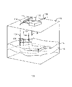
[0045] Fig. 1 is a drawing of a hydrocarbon recovery process 100 in
accordance
with embodiments. In the hydrocarbon recovery process 100, a reservoir 102 is
accessed by a first set 104 and a second set 106 of horizontal wells. As
described
herein, the wells can have a lateral spacing 108 of about 50 to 200 metres
between
each of the wells. The first set 104 may be drilled substantially proximate to
a base
- 10-
CA 02744749 2011-06-30
2011EM188-CA
110 of the reservoir 102. The second set 106 of horizontal wells may be
drilled at a
vertical spacing 112 of about three metres, or more, above the first set 104.
Although only two wells of each type are shown in the hydrocarbon recovery
process
100, any number may be used, for example, from one well of each type to
several
hundred wells of each type, depending on the size of the reservoir 102. The
first set
104 of horizontal wells may be coupled together by lines 114 at the surface.
Similarly, the second set 106 of horizontal wells may be coupled together by
lines
118 at the surface. One or more surface facilities 120 produce steam or
solvent
streams that can be injected into the reservoir through the sets of wells 104
or 106
and produce fluids from the sets of wells 104 or 106. The produced fluids may
be
separated at the surface facility 120 to produce a hydrocarbon stream 122,
which
can then be sent on for further processing.
[0046] After the sets of wells 104 and 106 are drilled, a cyclic production
process,
such as cyclic steam stimulation, may be used on both sets 104 and 106 of
horizontal wells in concert. During this period, the surface lines 114 and 118
may be
tied together so that the sets of wells 104 and 106 are used in concert. The
cyclic
production process is repeated until fluid communication between the first set
104
and the second set 106 of wells is detected. At that point, the second set 106
of
wells may be used for continuous injection of a mobilizing fluid, while the
first set 104
may be used for production, for example, of hydrocarbons and the mobilizing
fluid.
Establishing Fluid Communication
[0047] Figs. 2(A), (B), and (C) are 3D seismic views of a cyclic production
process 200 showing the establishment of fluid communications between
adjoining
wells. In Fig. 2, the particular cyclic production process used was cyclic
steam
stimulation (CSS), although any cyclic production technique could be used in
techniques described herein. Fig. 2(A) is an initial view showing accessed
areas
202, for example, areas that may be in heated and in fluid communication with
horizontal wells 204 after one cycle of cyclic steam injection and production
has
been performed from the reservoir 206. The accessed areas 202 may be termed
the
steam invaded region. The darker, shaded areas indicate regions 208 are not
yet in
fluid communication with the wells 204. As can be seen, the wells 204 are not
substantially in fluid communication with each other at this point in the
process, as
-11-
CA 02744749 2011-06-30
2011EM188-CA
indicated by the lack of overlap of the accessed areas 202 across adjacent
wells
204.
[0048] After a second cycle of steam injection and production, heated
features
extend out to at least about 25m from each well. In this example, the wells
are about
170 metres apart and fluid communication has not been completely established.
However, if the wells had been placed about 50 to 75 metres apart, basal
connections would have been established at this point. Thus, after two cycles
of
CSS the shown in Fig. 2(B), the accessed area 202 has substantially increased
in
size, and is overlapping a number of adjacent wells 204, for example, as
indicated by
reference number 210.
[0049] After a third year of cyclic production, as shown in Fig. 2(C), the
accessed
region 202 has placed all adjacent wells 204 in fluid communication, allowing
fluid
flow from any well to an adjacent well 204. Creating uniform connections along
the
wells may present a challenge. For example, reference number 212 identifies a
region where the fluid communication is not extensive, indicating that further
cycles
may be useful. However, the fluid communication may be extensive enough to
begin
continuous steamflooding. The wells shown in Figures 2 (A), (B) and (C) were
completed with specially designed completion which facilitated uniform steam
distribution, such as limited entry perforations (LEPs) which may be used in
concert
with a wire screen.
[0050] Fig. 3(A), (B), and (C) are cross sectional views 300 of the cyclic
production processes of Fig. 2(A), (B), and (C), respectively, showing the
establishment of fluid communications between adjoining wells 204. In Fig. 3,
like
numbers are as discussed above. In this figure, not every well 204 is labelled
in
order to simplify the diagram. The center 302 of the production zone 304
around
each well 204 is at a lateral spacing 108 of about 170 metres apart in this
example.
The increase in the accessed area 202 (Fig. 2) after each year of cyclic
production is
shown as the increase in size of the production zones 304 around each well
204.
Further, other layers 306 may develop accessed zones 308, which can contribute
to
fluid communication between wells. If the lateral spacing 108 between were
closer,
fluid communications between wells 204 would be established more quickly. For
example, if the spacing around the production zones 304 was at 100 metres, as
indicated by reference number 310, the wells 204 could start to interact after
only
- 12-
CA 02744749 2011-06-30
2011EM188-CA
two years of cyclic production. The wells 204 could be converted to
alternating
injectors and producers, as discussed with respect to Fig. 4. In some
embodiments,
the lateral well spacing 108 will be about 50 metres. The lateral well spacing
108
may range from about 20 metres to about 200 metres.
Changing to Continuous Production
[0051] Fig. 4 is a cross-section of a portion 400 of a reservoir 102,
showing two
horizontal wells 104 and 106 in the reservoir 102 used in a continuous
production
process, e.g., after fluid communication is established by a cyclic production
process. A first horizontal well 104 is drilled near a base of the reservoir
102. A
second horizontal well 106 is drilled at a lateral offset 108 and at a
shallower level,
i.e., with a positive vertical offset 112. In an embodiment, the vertical
offset 112 is
greater than about three metres. The second horizontal well 106 may be used as
an
injection well to inject a mobilizing fluid to move hydrocarbons in the
reservoir 102
towards the first horizontal well 402, as indicated by arrow 402.
[0052] During the injection, steam and other gases rise, as indicated by
arrow
404, forming a steam or production chamber 406. Liquids, including mobilized
hydrocarbons, condensate, solvents, and the like, fall, as indicated by arrow
408.
These liquids drain to the first horizontal well 104, as indicated by arrow
402, which
is used as a production well to remove the fluids from the production chamber
410.
Unlike a typical steam assisted gravity drainage (SAGD) process, which has no
lateral spacing between the injection and production well, the production
chamber
406, at or near the base of the reservoir, is formed by the offset of the two
horizontal
wells 102 and 104. The production chamber 406 may increase the total amount of
hydrocarbons that can be produced from the reservoir in a given period of
time,
versus a vertical SAGD steam chamber, and may increase the efficiency of the
injected mobilizing fluid. This is discussed in further detail with respect to
Figs. 5 and
6.
[0053] The production changes that may result from the techniques may be
modeled by creating a geologic model of the reservoir and using the geologic
model
to calculate the amounts of hydrocarbons produced. The geologic model may
include open hole log data, cased hole log data, core data, recovery process
well
trajectories, 2D seismic data, 3D seismic data, or other remote surveying
data, or
any combinations thereof. For example, prior to the start of recovery
operations, a
-13-
CA 02744749 2011-06-30
2011EM188-CA
geologic model can be created for the development area. Available open hole
and
cased hole log, core, 2D and 3D seismic data, and knowledge of the
depositional
environment setting can all be used in the construction the geologic model.
The
information generated by the geologic model may then be used in a reservoir
simulation model to provide predictions of fluid flow, reservoir geometry, and
the like.
[0054] The geologic model, reservoir model, and knowledge of surface access
constraints can then be used to complete the layout of the spaced horizontal
wells
and surface pads. After the horizontal wells have been drilled, data collected
during
their drilling as well as data collected during the operation of the recovery
process,
such as cased hole logs including temperature logs, observation wells,
additional
time lapse seismic or other remote surveying data, can be used to update the
geologic model, which may be used to predict the evolution of the depletion
patterns
as the recovery process matures. The depletion patterns within the reservoir
will be
influenced by well placement decisions, geological heterogeneity, well
failures, and
day to day operating decisions.
[0055] Following the operation of the thermal, thermal-solvent or solvent
based
recovery process for a suitable period of time, intervals of high hydrocarbon
depletion will create a series of discrete connections between adjacent wells
or well
pairs, depending on the recovery process. Knowledge of these connections is
gained through observances of interwell or interpattern communication of
fluids,
convergence of operating pressures, as well as via ongoing reservoir depletion
monitoring with tools such as time lapse 3D seismic. This information may then
be
used to determine the appropriate time to convert from a cyclic production
process to
a continuous production process.
[0056] Fig. 5 is a plot 500 showing a simulation of the increase in total
production
that may be obtained using the present techniques. In the plot 500, the x-axis
502
represents the time since production was started, while the y-axis 504
represents the
cumulative oil volume produced from the reservoir using basal planar gravity
drainage (BPGD). The total production 506 that could be achieved using the
present
techniques 506 quickly reaches a maximum, allowing a much faster production of
the resources. In contrast, the production 508 from a SAGD process may reach
the
same amounts, but only after many years.
- 14 -
CA 02744749 2011-06-30
2011EM188-CA
[0057] Fig. 6 is a plot 600 showing a simulation of the increase in
efficiency that
can be obtained using the present techniques. The x-axis 602 represents the
total
amount of steam injected into the reservoir, while the y-axis represents the
total
volume of oil produced from the reservoir. As can be seen in the plot 600, if
large
volumes of steam are injected the SAGD and BPGD processes result in the same
recovery levels. However, economic limits will dictate the actual volume of
steam
that can be practically injected. The benefit of the BPGD process, as
indicated by
comparing line 606 to a normal SAGD process, as indicated by line 608. For
example, comparing the two cases at 200,000 m3 of steam injection volume, SAGD
will have produced about 75,000 m3 of oil whereas the BPGD process will have
produced about 110,000 m3 of oil.
[0058] An assumption inherent in a BPGD process is that a connection can be
created between the injection well and the production well early in the
recovery
process. In the SAGD process a connection is typically established through a
warm-
up phase during which conductive heating is used to establish the connection.
Because conductive heating is a relatively slow process the wells are spaced
about
metres apart. It may also be useful to establish a distributed connection
along the
full length of the wells. If the connection or heated zone does not extend
over the full
length of the well then steam override may occur. For example, in areas within
the
reservoir, the steam chamber will rise to the top of the reservoir quickly and
will then
flow along the top of the reservoir to the producer. A similar situation often
occurs
when vertical wells are utilized for steamflooding. In order for a BPGD
process to be
most effective, the well can be configured such that the well lengths are much
longer
than the well spacing. Further, the wells can be completed with some form of
flow
control devices on the injector and producer such that the spacing of such
devices is
less than the well spacing, such as less than half than a distance between
adjacent
wells or less than a quarter of the distance between adjacent wells. The
tighter the
spacing of the perforations, the better the basal conformance. For example,
the well
lengths may be in the 300 to 1500 metres range, the well spacing in the 50 to
150
metres range and the flow control devices spaced every 10 to 50 metres along
the
well.
[0059] Fig. 7 is process flow diagram of a method 700 for a basal planar
gravity
drainage production of hydrocarbons. The method 700 begins at block 702 with
the
drilling of a first horizontal well at the base of the reservoir. The first
horizontal well
-15-
CA 02744749 2011-06-30
2011EM188-CA
may be around 500 to 1500 metres long. The base of the reservoir, or target
production zone, may be determined by a geological model, seismic imaging, or
any
number of techniques. The first horizontal well, which will be a production
well
during continuous operations, may be completed with LEP screen-type
completions
that are sized to allow distributed liquid in-flow along the length of the
well. The total
area of the perforations may be selected to limit the influx of vapour during
continuous production.
[0060] At block 704, a second horizontal well is drilled parallel to the
first
horizontal well, and is typically of the same length. The second horizontal
well may
be laterally offset between about 50 and 200 metres from the first horizontal
well.
The second horizontal well may be drilled three or more metres above the
completion depth of the first horizontal well. In a field having multiple
horizontal
wells, the depths of the horizontal wells may vary, depending on the base of
the
reservoir. However, neighbouring horizontal wells will generally have
alternating
depths. The second horizontal well, which will be an injection well during
continuous
operations, may be completed with limited-entry perforation (LEP) screen-type
completions that provide for evenly distributed steam injection where the
steam is
injected in the vapour phase. Typically, the LEP's in the second horizontal
well will
have a larger open area than those in the first horizontal well when the
mobilizing
fluid is injected as predominantly a vapour, for example, as steam, and
produced as
a liquid.
[0061] At block 706, fluid communication may be established between the
wells.
This may be performed by any number of cyclic production processes. For
example,
as discussed with respect to Fig. 2, cyclic steaming of horizontal wells with
LEP's
completions can create uniform basal heating that establishes fluid
communications
between adjacent wells. After about two to three cycles of CSS, the heated
features
between wells may overlap, and the wells may be converted to steamflood.
[0062] In some types of reservoirs, a basal plane gravity-drainage layer
may be
established by injecting a fluid at rates that induce fracturing. As such,
this
connection process is particularly suited to reservoirs where the stress state
favours
horizontal fractures. Most commonly reservoirs that favour horizontal
fractures are
found at depths shallower than about 500 m. It may also be possible in some
reservoirs to precondition the reservoir to favour horizontal fractures
through
- 16-
CA 02744749 2011-06-30
2011EM188-CA
pressurization. This may allow horizontal fractures to be generated at greater
depths. For example, this may be performed by injecting water, steam, or
solvents
to raise the reservoir pressure.
[0063] In
reservoirs where the stress state may not favour horizontal fractures,
solvent fingering may offer an alternate mechanism for generating connections.
Solvent fingering is a mechanism whereby a less viscous injected fluid invades
a
reservoir that is saturated with a more viscous fluid, and occurs when solvent
is
injected into heavy oil. It is known that solvent fingers will propagate
towards regions
of lower pressure. The connection can be generated by the cyclic injection and
production of solvent into the first horizontal, or production, well in order
to establish
a finger network of high mobility. Solvent may then be injected into the
second
horizontal, or injection well, generating a second network of fingers while
producing
from the first horizontal well. The shortest pathways between the injection
well and
production well would be expected to dominate the flow paths and establish a
basal
communication path.
[0064] Once fluid
communication is established between the first and second
horizontal wells, at block 708, the second horizontal well may be used as an
injection
well, with a continuously injected stream of a mobilizing fluid. The injected
mobilizing
fluids could be steam, solvent, hot water, or mixtures thereof. At block 710,
fluids
may be continuously produced from the first horizontal, or production, well.
[0065] While the
present techniques may be susceptible to various modifications
and alternative forms, the embodiments discussed above have been shown only by
way of example. However, it should again be understood that the techniques is
not
intended to be limited to the particular embodiments disclosed herein. Indeed,
the
present techniques include all alternatives, modifications, and equivalents
falling
within the true spirit and scope of the appended claims.
Embodiments
[0066] An embodiment of the present techniques provides a method for
producing hydrocarbons from a reservoir. The method includes drilling a first
horizontal well substantially proximate to a base of a reservoir and drilling
a second
horizontal well at a horizontal offset from the first horizontal well.
Fluid
communication is established between the first horizontal well and the second
horizontal well through cyclic production processes. A mobilizing fluid is
injected
- 17-
CA 02744749 2011-06-30
20-11EM188-CA
through the second horizontal well and fluids are produced from the first
horizontal
well.
[0067] The
horizontal offset may be between about 50 and 200 metres. The
second horizontal well may be about three metres, or more, shallower than the
first
well. Pressure on the reservoir may be equalized by conditioning.
[0068] The second horizontal well may be completed with limited entry
perforations (LEPs) configured to evenly distribute a steam injection. The
limited
entry perforations (LEPs) can be spaced at distances less than half of a
distance
between the first well and the second well. The first horizontal well can be
completed with limited entry perforations (LEPs) configured to provide a
substantially
even production of fluids. The limited entry perforations (LEPs) can be spaced
at
distances less than half of a distance between the first well and the second
well.
[0069] Fluid
communication can be established between the first horizontal well
and the second horizontal well by creating solvent fingers using cyclic
solvent
injection and production. Further, fluid communication can be performed
performed
by cyclic steam stimulation, cyclic solvent stimulation, or both.
[0070] Injecting a
mobilizing fluid can include steam injection, solvent injection, or
a mixed injection. The pressure in the reservoir may be raised to create
horizontal
fractures.
[0071] Another embodiment provides a system for harvesting resources in a
reservoir. The system includes a first horizontal well substantially proximate
to the
base of the reservoir and a second horizontal well at a horizontal offset from
the first
horizontal well, wherein the second horizontal well is vertically offset from
the first
horizontal well. A cyclic
production system is configured to establish fluid
communication between the wells. A continuous injection and production system
is
configured to inject a mobilizing fluid into the second horizontal well and
produce a
fluid from the first horizontal well.
[0072] A steam
generation system can be configured to provide steam for
injection. A separation system can be configured to separate a hydrocarbon
stream
from a produced fluid. A geologic model can be configured to locate the base
of the
reservoir.
[0073] Another embodiment provides a method for producing hydrocarbons. The
method includes producing fluids from a number of production wells in a
reservoir,
-18-
CA 02744749 2011-06-30
2011EM188-CA
wherein each of the production wells are located substantially proximate to
the base
of the reservoir. Mobilizing fluids are injected into the reservoir through a
number of
injection wells, wherein each of the plurality of injection wells is adjacent
to one of
the plurality of production wells. Further, each of the injection wells is
laterally offset
from each of the adjacent production wells, and each of the injection wells is
drilled
at a higher level than each of the adjacent production wells. A hydrocarbon
stream
is separated from the fluids produced from the plurality of production wells.
[0074] Each of the
injection wells can be drilled at a shallower level than each of
the adjacent production wells. The lateral offset may be between about 50 and
200
metres, and each of the injection wells may be at least about three metres
higher
than a neighbouring production well. Each of the plurality of production wells
can be
completed with a limited entry perforation screen configured to reduce the
entry of
vapour into the production well.
- 19-