Note: Descriptions are shown in the official language in which they were submitted.
CA 02745132 2011-06-30
LAMPPOST HEAD ASSEMBLY
Technical field
[0001] The present invention relates to lighting solutions and, more
specifically, to
adjustable Light Emitting Diode (LED)-based lighting solutions.
Background
[0002] A light-emitting diode (LED) transfers electric energy into photons by
electroluminescence. LED-based lighting solution has the advantages of being
resistant to
shock, have an extended lifetime under proper condition and better energy to
photon ratio than
incandescent solutions. A LED lighting lamp usually has higher brightness than
existing
incandescent lamps, but also produces narrower light beam. As such, when
deploying LED-
based lamps or when replacing existing incandescent lamps with LED-based
lamps, properly
adjusting light beams becomes a concern.
[0003] The present invention addresses the above issue.
Summary
[0004] A first aspect of the present invention is directed to a lamppost head
assembly
comprising a housing compartment having a cavity, a panel and at least one
fastener. The
panel has a plurality of Light Emitting Diodes (LEDs) positioned on a first
surface and a heat
sink positioned on a second surface opposite to the first surface. The heat
sink is adapted to fit
into the cavity for dissipating the panel's heat into the housing compartment.
The at least one
fastener maintains the panel at an angle with the housing compartment from a
plurality of
angle options and maintains the heat sink into the cavity.
[0005] The angle between the panel and the housing compartment allows to
determine a
distance at which a light beam from the panel is projected, for instance, away
from the housing
compartment or from a mounting point of the housing compartment.
[0006] Optionally, the heat sink may have a continuous surface in contact with
the cavity
formed by a series of heat sink fins. The heat sink may also have internal
fins between the
1
CA 02745132 2011-06-30
continuous surface and the panel. Another option is for the cavity to have a
continuous surface
in contact with the heat sink, which is formed by a series of fins.
[0007] The cavity may present various shapes. For instance, the cavity may
have a
semicircular channel shape. The angle between the panel and the housing
compartment would
then provide a single rotational and directional angle. The semicircular
channel shape may be
positioned perpendicularly from a longitudinal axis of the housing
compartment. The
semicircular channel shape may be continuous or be facetted to define a
plurality of surfaces
(e.g., providing one way of defining the plurality of angle options). In the
latter case, at least
one of the plurality of surfaces may further define a semicircular shape
(e.g., providing one
way of defining a limited set of angle options).
[0008] The cavity may also have a hemispherical socket shape. The angle
between the
panel and the housing compartment would then be determined in many directions.
The
hemispherical socket shape may be continuous.
[0009] The lamppost head assembly may further comprise a second panel having a
second
plurality of Light Emitting Diodes (LEDs) positioned on a first surface of the
second panel and
a second heat sink positioned on a second surface of the second panel,
opposite to the first
surface of the second panel.
[0010] The second heat sink may be adapted to fit into the cavity for
dissipating the
second panel's heat into the housing compartment. The at least one fastener
may optionally
maintain the second panel at the same angle as the panel and maintain the heat
sink into the
cavity. The at least one fastener may also optionally comprise at least a
first fastener that
maintains the panel at the angle and a second fastener that maintains the
second panel at a
second angle.
[0011] The second heat sink may also be adapted to fit into a second cavity of
the
lamppost head assembly for dissipating the second panel's heat into the
housing compartment.
At least a second fastener may then be used to maintain the second panel at a
second angle and
maintain the second heat sink into the second cavity. The angle between the
panel and the
housing compartment and the second angle between the second panel and the
housing
compartment may be substantially equal or different.
[0012] Optionally, the second panel may also be positioned over the same heat
sink as the
panel instead of the second heat sink.
2
CA 02745132 2011-06-30
[0013] The heat sink may comprise an extending lip positioned at one end and a
ledge
positioned at the other end. The at least one fastener, in this example, would
comprise a first
fastener that fixes the ledge to the housing compartment and a bracket fixed
to the housing
compartment that holds to the heat sink lip. The height of the bracket would
then determine
the angle between the panel and the housing compartment.
[0014] Optionally, the panel may also rotate within a panel frame. The at
least one
fastener would then comprise at least a first fastener that fixes the panel
frame to the housing
compartment, thereby maintaining the heat sink in the cavity. In this example,
as a first option,
the at least one fastener may also further comprise at least a second fastener
between the panel
and the panel frame to maintain the angle between the panel and the housing
compartment. As
a second option for this example, the at least one fastener may also comprise
at least a second
fastener between the heat sink and the cavity that maintains the angle (e.g.,
through friction
alone or with a series of pegs and holes or complementary shapes).
[0015] The housing compartment and the cavity may be cast in a single metallic
piece,
such as aluminum or aluminum alloy.
Brief description of the drawings
[0016] Further features and advantages of the present invention will become
apparent
from the following detailed description, taken in conjunction with the annexed
drawings, in
which:
Figure 1 is a perspective view of an exemplary lamppost head assembly in
accordance with the teachings of the present invention;
Figure 2 is an exploded view of an exemplary lighting panel assembly in
accordance with the teachings of the present invention;
Figure 3 is an exploded perspective view of an exemplary quad panel lamppost
head assembly showing a heat sink in a semicircular channel in accordance with
the teachings
of the present invention;
Figures 4A, Figure 4B, Figure 4C and Figure 4D herein referred to concurrently
as
Figure 4 are side views of an exemplary heat sink in a cavity in accordance
with the teachings
of the present invention;
3
CA 02745132 2011-06-30
Figure 5 is a side view of an exemplary facetted heat sink in accordance with
the
teachings of the present invention;
Figure 6 is a perspective view of exemplary heat sinks having hemispherical
shape
in accordance with the teachings of the present invention;
Figure 7 is a perspective view of an exemplary panel frame and heat sink in
accordance with the teachings of the present invention; and
Figure 8 is a perspective view of an exemplary complementary heat sink cavity
and panel heat sink in accordance with the teachings of the present invention.
Detailed description
[00171 The present invention provides the exemplary advantage of directing a
beam of
light at a desired distance from a lamppost. The solution of the present
invention is particularly
useful when applied to LED-based lighting, even though it is not limited to
this context. When
used in the context of multiple LED panels in a single housing compartment,
the solution of
the present invention may also provide another exemplary advantage of allowing
per-panel
adjustment of the light beam. Another exemplary advantage may be provided by
heat
dissipation being integrated in the light beam adjustment and still allowing
for conventional
lamppost head assembly design or housing compartment design, which may be
advantageous
especially in the context of equipment replacement.
[00181 Reference is now made to the drawings, in which Figure 1 shows an
exemplary
perspective view of a first lamppost head assembly 100 in accordance with the
teachings of the
present invention. The lamppost head assembly 100 is shown with a single
lighting panel
assembly 180 in its housing compartment 105. Reference is concurrently made to
Figure 1 and
Figure 2, which also shows the lighting panel assembly 180. The lighting panel
assembly 180
comprises a panel 110 that comprises a series of Light Emitting Diodes (LEDs)
182 positioned
on one of the panel's 110 surface. Conclusive tests were made with 28 Philips
LXML-PWCI-
0100 LEDs.
[00191 In order to protect the LEDs, the lighting panel assembly 180 may also
comprise a
cover 184, which could de snapped to the panel 110 or otherwise held over the
LEDs 182. One
or more fixed lenses 186 may be provided over each or some of the LEDs 182,
which could be
useful to better control the light beam produced by the panel 110. The fixed
lenses 186 may,
4
CA 02745132 2011-06-30
for instance, be molded in the cover 184. The fixed lenses 186 could also be
snapped of
otherwise fixed to the panel 110 over the LEDs 182, which may further avoid
the need for the
cover 184. In presence or absence of the cover 184, the housing compartment
105 could also
be covered (not shown). The exemplary cover 184 is shown in a translucent or
transparent
material, which may also be tinted to affect the light beam color or
temperature. The cover 184
could also be made partly or completely in opaque or semi opaque material (not
shown) with a
translucent or transparent face or face with holes (not shown), which could
further be adapted
to hold the fixed lenses 186. The fixed lenses 186 do not have to all be
identical.
[00201 The exemplary lighting panel assembly 180 also comprises a heat sink
114
adapted to fit onto the surface of the panel 110 opposite to the LEDs 182. The
heat sink 114
has a continuous surface in thermal contact with the panel 110. Skilled person
will readily
recognize the different means that can be used to ensure proper heat
dissipation from the panel
110 towards the heat sink 114, including, for instance, proper holding means
(not shown) and
a thermal compound (not shown) between the panel 110 and the heat sink 114.
The heat sink
114 has a plurality of fins 192 extending from the surface 188. The fins 192
are shown
extending to a continuous semi-circular surface 194. The heat sink 114 is
shown with an
optional groove 196, which may be used to electrically wire the panel 110.
Skilled reader will
readily appreciate that electrical power and other electronic components (not
shown) are
needed in order for the LEDs 182 to emit light within the desired parameters.
The electronic
components may be completely or partly provided on the panel 110 and/or within
the housing
compartment 105. The electrical power is delivered through wires (not shown)
via the groove
196 or otherwise.
[00211 Persons skilled in the art will readily recognize that the panel 110
could comprise
other LED types and/or a different number of LEDs. Likewise, the panel
assembly 180 could
be made with or without the cover 184. As will be shown with reference to
other Figures, the
shape of the heat sink 114 and the presence or shape of the surface 194 may
vary depending
on the shape and surface of the receiving cavity (not shown on Figure 2). In
absence of the
surface 194, some or all of the fins 192 would extend from the surface 188
towards the surface
of the receiving cavity, as will be shown later. As skilled reader will
appreciate, the shape and
surface adaptation between the receiving cavity and the heat sink 114 are
meant to ensure
proper heat dissipation from the panel 110 into the housing compartment 105.
While it is not
expected to be necessary, a thermal compound could also be used between the
heat sink 114
and the receiving cavity.
5
CA 02745132 2011-06-30
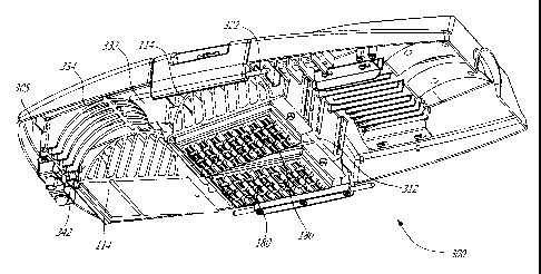
[0022] Figure 3 shows an exemplary exploded perspective view of a lamppost
head
assembly 300 in accordance with the teachings of the present invention. The
lamppost head
assembly 300 is shown with a housing compartment 305 of a capacity of 4
lighting panel
assemblies 180. To better illustrate the present invention, two lighting panel
assemblies 180
are shown in two cavities 312 and 322, cavity 332 is shown empty while only a
heat sink 114
is shown in cavity 342. The two cavities 312-322 or the two cavities 332-342,
in the
configuration shown on Figure 3, could each be considered as a single cavity.
Two panels
similar to the panel 110 could also be fixed to a single, larger heat sink
(not sown) to fit into
the single cavity.
[0023] In the example of Figure 3, the cavities 312-322-332-342 are semi
circular in
shape and define a channel. Each exemplary channel is perpendicular to a
longitudinal axis of
the housing compartment 305 and is formed by multiple fins that extend within
the housing
compartment 305. An exemplary contact surface 334 formed the multiple fins of
the cavity
332 is shown. The surface 334 receives heat from the heat sink 114 (e.g., via
a thermal
bridge). A continuous contact surface (not shown) could also be provided to
receive a heat
sink that exposes fins thereto (not shown in Figure 3).
[0024] Figure 4A, Figure 4B, Figure 4C and Figure 4D are herein referred to
concurrently
as Figure 4. Reference is made concurrently to Figure 3 and Figure 4, which
shows a side view
of the heat sink 114 and the cavity 342. The heat sink 114 has a complementary
curved shape
adapted to fit into the cavity 342. The channel of the cavity 342 may be
defined by an arc of x
degrees in a circle with a radius r. In such an example, the heat sink 114
would be defined by
an arc of y degrees in a circle with a radius r', with y larger than x and r
substantially equal to
r', within expected tolerances or with r' slightly smaller than r to ensure
easier fit without
compromising heat transfer. Persons skilled in the art will readily be able to
determined proper
values of r, r' and other dimensions of the different components to fit
different needs. The
difference between y and x defines a potential rotational angle of the heat
sink 114 within the
cavity 342 versus the housing compartment 305. Since the panel 110 is attached
to the heat
sink 114, the angle between the heat sink 114 and the housing compartment 305
are linked.
When the panel 110 is parallel to the heat sink 114, both angles are equal. A
fixed angle
between the heat sink 114 and the panel 110 could also be used. Maintaining
the angle
between the heat sink 114 and the housing compartment 305 also maintains the
angle between
the panel 110 and the housing compartment 305, no matter if the panel 110 and
the heat sink
114 are parallel or not. The angle between the panel 110 and the housing
compartment 305
6
CA 02745132 2011-06-30
determines the angle at which a light beam is projected away from the housing
compartment
305. Hence, the angle between the panel 110 and the housing compartment 305
also
determines a distance at which a light beam from the panel 110 is projected
away from a
mounting point of the housing compartment 305.
100251 The circular or semi-circular shape allows for an infinite number of
choices as to
the angle between the panel 110 and the housing compartment 305. In order to
fix the value of
the rotational angle between the heat sink 114 and the housing compartment 305
(e.g., to a
value A), a fastener such as a bracket 480 can be used. The height h of the
bracket 480 will
allow to maintain the heat sink 114 at the desired rotational angle A. On the
example of Figure
4, one end of the exemplary bracket 480 is shown with a gutter adapted to fit
an extending lip
478 of the heat sink 114. Once the bracket 480 is fixed onto the housing
compartment 305
(e.g., using a screw 482), another fastener such as screw 484 can be used to
secure a ledge 476
of the heat sink 114 in place. Skilled reader will recognize that length of
the screw 484 has to
take into account the height of the bracket 480. The bracket 480 on the lip
478 and the screws
482-484 maintain the heat sink 114 at the desired rotational angle A and also
maintain the heat
sink 114 within the cavity 342. It should be noted that the bracket 480 could
be long enough to
maintain two or more parallel heat sinks in their respective cavities
maintaining the same
angle for all heat sinks. A bracket 480' presenting more than one gutters
could also be used to
provide multiple choices of angles at once. The bracket 480' may be of
variable length to
maintain a single heat sink or a number of parallel heat sinks.
[00261 The torque applied to the exemplary screws 482 and 484 needs to be
determined to
maintain necessary contact between the heat sink 114 and the cavity 342 to
ensure expected
heat dissipation. Alternatively, a rotatable spring loaded screw 484' could
also be used to
maintain the heat sink 114 in the cavity 342. The spring loaded screw 484' is
rotatably
attached to the housing compartment 305. Once put in place over the ledge 476,
the spring
loaded screw 484' is released. The spring loaded screw 484' provides an
exemplary advantage
of maintaining a constant pressure over the heat sink 114 to ensure expected
thermal bridge
towards the housing compartment 305 and is expected to do so over a longer
period of time
when compared to the screw 484.
[00271 Alternatively, a cavity 342' could be defined by a semi-circular shape
that has
more than 180 degrees. A heat sink 114' could thereby be maintained in the
cavity 342' by the
cavity 342' itself. The heat sink 114' could be inserted sideways into the
cavity 342' or the
cavity 342' could be formed by more than one part (not shown) closed over the
heat sink 114'.
7
CA 02745132 2011-06-30
[0028] Persons skilled in the art will readily determine proper dimensioning
of the screws
482, 484 and 484' as well as material used for the screws and the housing
compartment 305 in
view of the desired heat transfer results. Bushings, spacers or the like could
be used, for
instance, between the heat sink 114 (e.g., the ledge 476 and/or the extending
lip 478) and the
housing compartment 305. For instance, a spacer of length determined by the
height h of the
bracket 480 could be used on the screw 484, between the ledge 476 and the
housing
compartment 305, thereby providing a guide toward proper torque and reducing
the risk of
striping the screw 484 and/or the screw hole. It is expected that common
aluminum alloy will
be used to cast the housing compartment 305 in a single piece also defining
the cavities, which
may further be milled or machined in preparation for final use (e.g.,
preparing pre-holes for
the various screws, preparing surfaces of the cavities for thermal bridge,
etc.). The heat sink
114 is also expected to be made of aluminum or aluminum alloy in a single
piece. Persons
skilled in the art will recognize that other configuration than a one-piece
cast housing
compartment 305 and/or heat sink 114 can also be suited for the intended
purpose.
[0029] Figure 5 shows a side view of an exemplary facetted heat sink 514 in
accordance
with the teachings of the present invention. Figure 5 shows a first facetted
configuration with
multiple straight panels 550 forming a facetted surface 594. Figure 5 also
shows a second
facetted configuration with multiple curved panels 560 forming the facetted
surface 594. The
curved panels 560 are shown convex, but a concave configuration (not shown)
could also be
used. Based on the shape of the heat sink 514, a cavity of the housing
compartment also needs
to be correspondingly made to receive the heat sink 514 so as to allow heat
dissipation from
the heat sink 514 into the housing compartment. Skilled reader will readily
recognize that the
number of surfaces 550 and 560 shown is chosen for clarity and that a larger
(or smaller)
number of surfaces could be chosen. The number of surfaces determines the
number of
choices given for angle adjustment. A mix of straight panel(s) and curved
panel(s) could also
be used, for instance, in order to further limit the number of choices given
for angle
adjustments. A cavity configured to receive a single straight or curved panel
combined with
different heat sink configurations that provide a single straight or curved
panel at different
positions could allow off-site determination of the angle and thereby ensure
unique and proper
positioning on-site.
[0030] The heat sink 514 also shows exemplary fins 592 extending towards the
surface
594, some of them not extending all the way through. The exemplary fins' 592
configuration
8
CA 02745132 2011-06-30
and the facetted surfaces 560 and 550 are optional features that could be used
together or
independently.
[00311 Figure 6 shows a perspective view of exemplary heat sinks 614 and 614'
having
hemispherical shape in accordance with the teachings of the present invention.
In such an
exemplary configuration, the angle between a panel and a housing compartment
could be
determined in many directions. The heat sinks 614 and 614' show a partial
hemispherical
shape, but skilled reader will readily recognize that other options are
possible. The heat sink
614 is shown with a continuous surface 694, which could make fins 692
difficult to obtain.
The heat sink 614' is shown with a discontinuous surface 694', which would
require a
different configuration of a receiving cavity (e.g., continuous or partly
continuous surface to
ensure heat transfer).
[00321 Figure 7 shows a perspective view of an exemplary panel frame 770 and
heat sink
714 in accordance with the teachings of the present invention. The heat sink
can be rotatably
attached to the panel frame 770 through pegs 772 or other means. The panel
frame 770 can
then be fixed to the housing compartment (screws or press fit design)
Alternatively, the panel
or panel cover (not shown on Figure 7) instead of the heat sink 714 could be
rotatably attached
to the panel frame 770. Another fastener (not shown) could be used between the
panel, the
cover or the heat sink 714 and the panel frame 770 to maintain the angle
between the panel
and the housing compartment. This configuration would allow off-site angle
determination
and predictable on-site installation. Alternatively, the heat sink 714 and its
receiving cavity
may be adapted to maintain the angle (friction alone, pegs and holes,
complementary shapes,
etc.). This configuration may allow on-site angle determination for greater
flexibility.
[00331 Figure 8 shows a perspective view of an exemplary complementary heat
sink
cavity 842 of a housing compartment and a heat sink 814 in accordance with the
teachings of
the present invention. A LED panel (not shown) is meant to be maintained to
the heat sink
814. The cavity 842 is defined by a plurality of heat sinks fins 840 extending
outwardly. The
plurality of heat sinks fins 840 define a surface 834 that receives heat from
the heat sink 814
(e.g., via a thermal bridge). The heat sink 814 could be in contact with the
surface 834 on both
sides of its fins (as shown) or on only one side (not shown). Persons skilled
in the art will be
able to determine the required contact surface 834 based on the heat
dissipation need. In the
example of Figure 8, a pivot point 850 receives a peg or other fastener (not
shown) to allow
the heat sink 814 to rotate in the cavity 842. The heat sink fins 840 are
shaped so as to allow
the heat sink 814 to enter into the cavity 842 to provide a plurality of angle
options. While the
9
CA 02745132 2011-06-30
pivot point 850 is shown eccentric to the heat sink 814, it could also be
located in any other
location (e.g., the center), which would require defining a different shape of
cavity 842 via the
heat sink fins 840. Another fastener (not shown) could be used between the
heat sink 814 and
the cavity 842 to maintain the angle between the panel and the housing
compartment. This
other fastener could simply be friction between the contact surface 834 and
the heat sink 814.
Another exemplary alternative is to have one or more wings extending towards
the heat sink
fins 840 (not shown) or from a cover (not shown) 860 to receive. A peg (not
shown) may be
used through the heat sink 814 and the wing 860, screws (not shown) or
complementary
shapes from the heat sink 814 (not shown) may also be used as a fastener. The
one or more
wings could be located parallel or perpendicular to the longitudinal axis of
the heat sink 814,
in which case the wing will be curved to follow the heat sink 814 during
rotation.
[0034] Skilled reader will appreciate that different fasteners could be used
to fix, maintain
or secure parts together without affecting the present invention, such as
screws, screws and
bolts, rivets, nails, pins, piston pins, brackets, cramps, clamps, braces,
buckles, hooks, clips,
clasps, snaps, press fit mounting, retaining rings, pegs and holes, zippers,
tacks, etc.
[0035] The description of the present invention has been presented for
purposes of
illustration but is not intended to be exhaustive or limited to the disclosed
embodiments. Many
modifications and variations will be apparent to those of ordinary skill in
the art. The
embodiments were chosen to explain the principles of the invention and its
practical
applications and to enable others of ordinary skill in the art to understand
the invention in
order to implement various embodiments with various modifications as might be
suited to
other contemplated uses.