Note: Descriptions are shown in the official language in which they were submitted.
CA 02745146 2015-09-16
a
IMPLANT SYSTEMS AND METHODS
FOR TREATING OBSTRUCTIVE SLEEP APNEA
FIELD OF THE INVENTION
[0002] The present invention generally relates to treating sleep
disorders, and more
specifically relates to implant systems, devices and methods for treating
patients suffering from
obstructive sleep apnea.
DESCRIPTION OF THE RELATED ART
[0003] Obstructive sleep apnea (OSA) is caused by a blockage of the
airway, which usually
occurs when the soft tissue in the throat collapses and closes during sleep.
According to the
National Institutes of Health, OSA affects more than twelve million Americans.
During each
apnea event, the brain briefly arouses the sufferer in order to initiate the
resumption of
breathing. This type of sleep, however, is extremely fragmented and of poor
quality. When left
untreated, OSA may result in high blood pressure, cardiovascular disease,
weight gain,
impotency, headaches, memory problems, job impairment, and/or motor vehicle
crashes.
Despite the seriousness of OSA, a general lack of awareness among the public
and healthcare
professionals results in the vast majority of OSA sufferers remaining
undiagnosed and
untreated.
[0004] There have been a number of efforts directed to treating OSA.
For example, devices
for electrically stimulating the soft palate to treat snoring and obstructive
sleep apnea are
disclosed in U.S. Patent Nos. 5,284,161 and 5,792,067. These devices have had
mixed results
because they require patient adherence to a regimen of use, subject the
patient to discomfort
during sleep, and result in repeated arousal of the patient.
[0005] Another treatment, commonly referred to as continuous positive
airway pressure
(CPAP), delivers air into a patient's airway through a specially designed
nasal mask or pillow.
The flow of air creates positive pressure when the patient inhales to keep the
airway open.
CPAP is considered by many to be an effective non-surgical treatment for the
alleviation of
1
CA 02745146 2011-05-30
WO 2010/065341 PCT/US2009/065293
snoring and obstructive sleep apnea, however, patients complain about
discomfort caused by
the mask and hoses, including bloating, nasal drying, and dry eyes. As a
result, patient
compliance for CPAP is only about 40%.
[0006] Surgical treatments have also been used to treat OSA. One such
treatment is
referred to as uvulopalatopharyngoplasty, which involves removing about 2 cm
of the trailing
edge of the soft palate to reduce the soft palate's ability to flutter between
the tongue and the
pharyngeal wall. Another procedure uses a surgical laser to create scar tissue
on the surface of
the soft palate, which reduces the flexibility of the soft palate for reducing
snoring and/or closing
of the air passage. Yet another procedure, commonly referred to as cautery-
assisted palatal
stiffening operation (CAPSO), is an office-based procedure performed under
local anesthesia
whereby a midline strip of soft palate mucosa is removed, and the wound is
allowed to heal
whereupon the flaccid palate is stiffened.
[0007] Surgical procedures such as those mentioned above continue to have
problems.
More specifically, the area of tissue that is surgically treated (i.e.,
removal of palatal tissue or
scarring of palatal tissue) is often larger than is necessary to treat the
patient's condition. In
addition, the above-mentioned surgical procedures are often painful with
extended,
uncomfortable healing periods. For example, scar tissue on the soft palate may
present a
continuing irritant to the patient. Furthermore, the above procedures are not
reversible in the
event of adverse side effects.
[0008] Another implant system, sold under the trademark REPOSETM by
InfluENT of
Concord, NH, uses a titanium bone screw that is inserted into the posterior
aspect of the
mandible at the floor of the mouth. A loop of suture is passed through the
tongue base and
attached to the mandibular bone screw. The ReposeTM procedure achieves a
suspension or
hammock of the tongue base making it less likely for the base of the tongue to
prolapse during
sleep. Due to the high activity of the tongue during wakefulness, however, the
suture
component of this device may act as a "cheese cutter" to the tongue, causing
device failure and
requiring subsequent removal.
[0009] Another effort for treating OSA involves creating an auxiliary
airway for bypassing the
clogged portion of the main airway. In one embodiment of commonly assigned
U.S. Patent
2
CA 02745146 2015-09-16
Application Serial No. 12/182,402, filed July 30, 2008, an auxiliary airway is
formed by
implanting an elongated conduit beneath a pharyngeal wall of the pharynx. The
elongated
conduit has a proximal end in communication with a first region of the
pharynx, a distal end in
communication with a second region of the pharynx, and an intermediate section
extending
beneath the pharyngeal wall for bypassing an oropharynx region of the pharynx.
[0010] Magnets have also been used for treating OSA. For example, in one
embodiment of
commonly assigned U.S. Patent Application Serial No. 12/183,955, filed July
31, 2008, a
magnetic implant includes a bone anchor, a first magnet coupled to the bone
anchor, a tongue
anchor, a second magnet coupled to the tongue anchor, and a support for
aligning the first and
second magnets so that a repelling force is generated between the magnets for
urging the
second magnet away from the first magnet and toward the bone anchor. The
support maintains
the first magnet at a fixed distance from the bone anchor, aligns the first
magnet with the
second magnet, and guides movement of the first and second magnets. The
magnetic implant
disclosed in one or more embodiments of the '955 application does not have a
hard stop so as
to avoid the "cheese-cutter" effect observed when using implants having a hard
stop.
[0011] In one embodiment of commonly assigned U.S. Patent Application
Serial No.
12/261,102, filed October 30, 2008, an implant for treating obstructive sleep
apnea includes an
elongated element having a central area implantable in a tongue, the elongated
element
including a first arm extending from a first end of the central area and a
second arm extending
from a second end of the central area, with the first and second arms
extending through the
tongue and being anchored to the inframandibular musculature.
[0012] In spite of the above advances, there remains a need for additional
systems, devices
and methods for treating OSA through minimally invasive approaches that
provide long term
results, that encourage patient compliance, and that minimize patient
discomfort.
3
CA 02745146 2011-05-30
WO 2010/065341 PCT/US2009/065293
SUMMARY OF THE INVENTION
[0013] A system is provided for treating obstructive sleep apnea. The
system includes a
first implant adapted for implantation in an inframandibular region and having
at least one
aperture therethrough, and a ribbon-like element having first and second ends
and a
substantially uniform, non-circular cross section along its length. The ribbon-
like element is
adapted for implantation in a tongue with the first and second ends extending
through the at
least one aperture in the first implant for coupling the ribbon-like element
with said first implant.
The first implant may further include a cover portion, a base portion, and an
anchor element
positioned therebetween, with the anchor element having at least one aperture
therethrough. In
alternate embodiments, the anchor element has a stiffness greater than, and is
smaller than,
said cover and base portions, and/or may be made of a biocompatible, non-
resorbable material
such as silicon, polyurethane, polypropylene, polyethylene, polyurethane,
stainless steel, nitinol,
tantalum or titanium. The cover and base portions may also be made a
biocompatible mesh or
a biocompatible fabric, such as a resorbable mesh or fabric, and the anchor
element may also
be made of a mesh.
[0014] Also provided is a method for treating obstructive sleep apnea
including the steps of
implanting a first implant having at least one aperture therethrough in an
inframandibular region,
implanting at least a portion of a ribbon-like element having first and second
ends and a
substantially uniform, non-circular cross-section along its length in a
tongue, passing the first
end of the ribbon-like element through the at least one aperture in the first
implant, and passing
the second end of the ribbon-like implant through the at least one aperture in
the first implant.
[0015] The method may further include, following the second passing step,
coupling the first
and second ends of the ribbon-like element together to thereby secure the
ribbon-like element
to the first implant. Further, prior to the coupling step, the method may
further include pulling on
the first and/or second ends of the ribbon-like element to thereby adjust the
position of the
ribbon-like element relative to the first implant, and/or pulling on the first
and/or second ends of
the ribbon-like element to increase the distance between the base of tongue
and the posterior
pharyngeal wall. The first implant may be made of a non-resorbable,
biocompatible mesh or
fabric, and/or include a mesh portion and an anchor having a stiffness greater
than the mesh
portion and having at least one aperture therethrough.
4
CA 02745146 2011-05-30
WO 2010/065341 PCT/US2009/065293
[0016] Finally, a kit is provided for treating sleep apnea that includes a
first implant adapted
for implantation in an inframandibular region, a ribbon-like element having
first and second ends
and a substantially uniform, non-circular cross-section along its length, and
adapted for
implantation in a tongue and for coupling with the first implant, at least one
introducer, and at
least one snare adapted to be passed through the introducer and having a
distal end adapted to
couple with the first end of the ribbon-like element.
[0017] The kit may further include a suture having first and second ends,
and a needle
element coupled to the first end. In yet another embodiment, the kit may
further include a
second ribbon-like element having first and second ends and adapted for
implantation in a
tongue and for coupling with the first implant. In alternate embodiments, the
first ribbon-like
element may be made of expanded polytetrafluoroethylene and/or the first
implant may further
include a cover portion, a base portion, and an anchor element positioned
therebetween, with
the anchor element having at least one aperture therethrough.
[0018] In yet another embodiment, the anchor element is made of a
biocompatible, non-
resorbable material, such as silicon, polyurethane, polypropylene,
polyethylene, polyurethane,
stainless steel, nitinol, tantalum or titanium.
[0019] In yet another alternative embodiment, the kit further includes a
washer that is
adapted to be placed between the ribbon-like element and first implant.
[0020] In yet another embodiment, the kit further includes a balloon that
is adapted to be
placed between the ribbon-like element and the first implant. A filling
reservoir may be coupled
to the balloon.
[0021] These and other preferred embodiments of the present invention will
be described in
more detail below.
BRIEF DESCRIPTION OF THE DRAWINGS
[0022] FIG. 1 shows a cross-sectional view of a human head including a
nasal cavity and a
pharynx.
CA 02745146 2011-05-30
WO 2010/065341 PCT/US2009/065293
[0023] FIG. 2 shows a cross-sectional view of the nasal cavity and the
pharynx of a human
during normal breathing.
[0024] FIG. 3 shows a cross-sectional view of the nasal cavity and the
pharynx of a human
having an airway that is at least partially closed.
[0025] FIG. 4A shows a system for treating obstructive sleep apnea
including a first implant
part implantable in inframandibular tissue, in accordance with one embodiment
of the present
invention.
[0026] FIG. 4B shows a system for treating obstructive sleep apnea
including the first
implant part implantable in inframandibular tissue and a second implant part
implantable in a
tongue, in accordance with one embodiment of the present invention.
[0027] FIGS. 5A-5C show the second implant part of FIG. 4B, in accordance
with one
embodiment of the present invention.
[0028] FIGS. 6A and 6B show a method of treating obstructive sleep apnea
including
implanting a first implant part in an inframandibular region, in accordance
with one embodiment
of the present invention.
[0029] FIGS 7A and 7B show a method of treating obstructive sleep apnea
including
implanting a second implant part in a tongue, in accordance with one
embodiment of the
present invention.
[0030] FIGS. 8A and 8B show the second implant part of FIGS. 5A-5C
implanted in a
tongue, in accordance with one embodiment of the present invention.
[0031] FIG. 9 shows an implant system for treating obstructive sleep apnea,
in accordance
with one embodiment of the present invention.
[0032] FIG. 10 shows an implant system for treating obstructive sleep
apnea, in accordance
with one embodiment of the present invention.
6
CA 02745146 2011-05-30
WO 2010/065341 PCT/US2009/065293
[0033] FIGS. 11A-11B illustrate one embodiment of a ribbon-like element of
an alternative
implant system according to the present invention.
[0034] FIGS. 12A-12B illustrate one embodiment of a first implant that can
be used with the
ribbon-like element of Figs. 11A-11B.
[0035] FIGS. 13A-13E illustrate alternate embodiments of the first implant
of Figs. 12A-12B.
[0036] FIG. 14 illustrates an implant such as that shown in Figs. 11-12
implanted in the
body.
[0037] FIG. 15 illustrates an exemplary kit according to the present
invention.
[0038] FIG. 16 illustrates an exemplary implant including first and second
ribbon-like
elements implanted in the body.
[0039] FIG. 17a-f illustrate a method for implanting the implant of Figs.
11-12.
[0040] Figs. 18a-b illustrate an exemplary adjustment element according to
the present
invention.
[0041] Fig. 19 illustrates an alternative adjustment element according to
the present
invention.
DETAILED DESCRIPTION
[0042] FIG. 1 shows a cross-section of a human head with anatomical
structures including
the nasal cavity N, bone B of the hard palate HP, the soft palate SP, the
mouth M, the tongue T,
the trachea TR, the epiglottis EP, the esophagus ES, and the posterior
pharyngeal wall PPW.
In the human head, an air filled space between the nasal cavity N and the
larynx LX is referred
to as the upper airway. The most critical part of the upper airway associated
with sleep
disorders is the pharynx PX.
[0043] Referring to FIG. 2, the pharynx has three different anatomical
levels. The
nasopharynx NP is the upper portion of the pharynx located in the back of the
nasal cavity N.
The oropharynx OP is the intermediate portion of the pharynx containing the
soft palate SP, the
7
CA 02745146 2011-05-30
WO 2010/065341 PCT/US2009/065293
epiglottis EP, and the curve at the back of the tongue T. The hypopharynx HP
is the lower
portion of the pharynx located below the soft tissue of the oropharynx OP. The
oropharynx OP
is the section of the pharynx that is most likely to collapse due to the high
prevalence of soft
tissue structure, which leaves less space for airflow. The hypopharynx HP lies
below the
aperture of the larynx and behind the larynx, and extends to the esophagus.
[0044] As is well known to those skilled in the art, the soft palate and
the tongue are both
flexible structures. The soft palate SP provides a barrier between the nasal
cavity N and the
mouth M. In many instances, the soft palate SP is longer than necessary and
extends a
significant distance between the back of the tongue T and the posterior
pharyngeal wall PPW.
[0045] Although the muscles relax throughout the body during sleep, most of
the muscles of
the respiratory system remain active. During inhalation, the diaphragm
contracts and causes
negative pressure to draw air A into the nasal cavity N and the mouth M. The
air then flows
past the pharynx PX, through the trachea TR and into the lungs. The negative
pressure causes
the tissue of the upper airway to deform slightly, which narrows the airway
passage. In apneic
patients, the soft palate SP, the tongue T, and/or the epiglottis EP collapse
against the posterior
pharyngeal wall PPW to block airflow into the trachea. As the airway narrows,
airflow through
the pharynx becomes turbulent which causes the soft palate SP to vibrate,
generating a sound
commonly known as snoring.
[0046] During sleep, humans typically experience brief obstructions of
airflow and/or small
decreases in the amount of airflow into the trachea and lungs. An obstruction
of airflow for more
than ten seconds is referred to as apnea. A decrease in airflow by more than
fifty percent is
referred to as hypopnea. The severity of sleep disorders is measured by the
number of apneas
and hypopneas that occur during every hour of sleep.
[0047] If apnea or hypopnea occurs more than five times per hour, most
medical personnel
diagnose the individual as having an upper airway resistance problem. Many of
these patients
often exhibit symptoms related to sleep disorders including sleepiness during
the day,
depression, and difficulty concentrating.
8
CA 02745146 2011-05-30
WO 2010/065341 PCT/US2009/065293
[0048]
Individuals having ten or more episodes of apnea or hypopnea during every hour
of
sleep are officially classified as having obstructive sleep apnea syndrome. As
the airway is
obstructed, the individual makes repeated attempts to force inhalation. Many
of these episodes
are silent and are characterized by movements of the abdomen and chest wall as
the individual
strains to draw air into the lungs. Typically, episodes of apnea may last a
minute or more.
During this time, oxygen levels in the blood will decrease. Ultimately, the
obstruction may be
overcome by the individual generating a loud snore or awakening with a choking
feeling.
[0049]
Referring to FIG. 2, when an individual is awake, the back of the tongue T and
the
soft palate SP maintain their shape and tone due to their respective internal
muscles. As a
result, the airway A through the pharynx remains open and unobstructed. During
sleep,
however, the muscle tone decreases and the posterior surface of the tongue and
the soft palate
become more flexible and distensible.
[0050]
Referring to FIG. 3, without normal muscle tone to keep their shape and to
keep
them in place either alone or as a group, the posterior surface of the tongue
T, the epiglottis EP,
and the soft palate SP tend to easily collapse to block the airway A.
[0051]
Referring to FIG. 4A, in one embodiment an implant 20 used for treating
obstructive
sleep apnea may include a first implant part 22 or anchoring element
implantable in an
inframandibular region IR of a head. The first implant part 22 may be
implanted between tissue
planes in the inframandibular region IR, or alternatively between geniohyoid
musculature and
mylohyoid musculature, or between mylohyoid and digastrics muscles. The first
implant part 22
desirably includes a biocompatible, flexible pad such as a mesh or fabric pad,
a woven or
knitted mesh, a non-woven or non-knitted mesh, a flat braid comprised of
polypropylene or any
combination of the above materials. The first implant part 22 may also be made
of stainless
steel, nitinol, silicone, polyethylene, or polytetrafluoroethylene, and/or
resorbable synthetic
polymers such as polylactide, polyglycolide, polydioxanone, polycaprolactone,
or co-polymers
thereof. The first implant part may include a film having openings, pores, or
perforations for
enabling tissue ingrowth, or may include a resorbable film having non-
resorbable particles or
fibers that precipitate the formation of scar tissue.
A sclerosing agent may be used in
combination with the first implant part to encourage the formation of scar
tissue on, in and/or
around the first implant part. Energy such as laser energy or heat may also be
used to form the
9
CA 02745146 2011-05-30
WO 2010/065341 PCT/US2009/065293
scar tissue in the inframandibular region. The scar tissue desirably provides
a soft tissue
anchor in the inframandibular region of an oral cavity, and is preferably a
scar plane or scar
plate that lies in the inframandibular region. The anchoring element provided
in the
inframandibular region may also only include scar tissue that is formed
without requiring the
implantation of a first implant part.
[0052] The first implant part or anchoring element 22 may also include a
mesh or fabric pad
having a sclerosing agent provided thereon that is implanted in the
inframandibular region. The
mesh or fabric pad is left in place as scar tissue forms at least partially
on, in and/or around the
mesh or fabric pad. After a period of time, the newly formed scar tissue
defines a mass of scar
tissue such as a scar plane or scar plate that is disposed in the
inframandibular region. The
scar tissue preferably provides a soft anchor in the inframandibular region
that may be coupled
with an implant part disposed in a tongue, or coupled with a hyoid bone.
[0053] The first implant part 22 may have a size and shape that may be
modified by a
surgeon at the time of implantation. In one embodiment, a square of
biocompatible mesh or
fabric has dimensions of about four inches in length and about four inches in
width. During
surgery, the surgeon may cut the mesh or fabric into a size and shape
reflecting the surgical
needs of a patient, such as a rectangle, square, elliptical, or surgical
shape.
[0054] Referring to FIG. 4B, the implant 20 may further include a second
implant part 24
implantable in a tongue T. The second implant part 24 may be elongated and may
include a
filament, a braided tube, or a braided barbed tube having a first end 26 and a
second end 28.
The second implant part 24 preferably includes a buttress section 30 at a
center portion thereof.
The second implant part 24 also desirably includes a first arm 32 extending
between the
buttress section 30 and the first end 26, and a second arm 34 extending
between the buttress
section 30 and the second end 28. The buttress section 30 desirably forms the
widest and/or
largest diameter portion of the second implant part 24, and desirably has a
greater width and/or
diameter than the diameter of the respective first and second arms 32, 34. The
wider buttress
section 30 preferably provides enhanced anchoring of the second implant part
24 in the tissue
of the tongue T, and minimizes the likelihood of movement of the second
implant part in the
tongue.
CA 02745146 2011-05-30
WO 2010/065341 PCT/US2009/065293
[0055] The first and second arms 32, 34 projecting from the buttress may
further have
barbs. The barbs desirably enhance attachment of the first and second arms of
the second
implant part to the first implant part and/or the scar plane formed about the
first implant part. In
one embodiment, the barbs on the respective first and second arms project in
opposite
directions.
[0056] The second implant part 24 may be formed from non-absorbable
materials,
absorbable materials, or a combination of non-absorbable and absorbable
materials. The non-
absorbable materials may include polymeric materials such as non-resorbable
polymers,
silicone, polyethylene terephalate, polytetrafluoroethylene, polyurethane and
polypropylene,
nitninol, stainless steel, and/or composite materials. Suitable resorbable
polymers may include
polylactide, polyglycolide copolymers, polycaprolactone, and/or collagen.
[0057] The first implant part 22 preferably serves as a "soft anchor" for
the second implant
part positioned in the tongue. In one embodiment, the spacing between the
first implant part 22
and the second implant part 24 may be adjusted by pulling the first and second
arms 32, 34 of
the second implant part toward the first implant part so as to shorten the
length of the arms
between the two implant parts. The second implant part in the tongue is
preferably advanced in
an anterior and/or inferior direction so as to prevent the tongue from sealing
against the back
wall of the pharynx. The arms are preferably secured to the first implant part
so as to maintain
the tongue in the forward shifted position. The distal ends 26, 28 of the
first and second arms
32, 34 are preferably secured to the first implant part 22 using methods and
devices that are
described in more detail herein.
[0058] Referring to FIG. 5A, in one embodiment, the second implant part 24
or tongue
implant desirably includes the first end 26 and the second end 28. The
elongated second
implant part 24 preferably includes the buttress section 30 at the center
portion thereof, the first
arm 32 located between the buttress section 30 and the first end 26, and a
first needle 36
secured to the free end 26 of the first arm 32. The second implant part 24
also preferably
includes the second arm 34 extending between the buttress section 30 and the
second end 28
thereof, and a second needle 38 secured to the free end 28 of the second arm
34. In one
embodiment, the buttress section 30 desirably forms the widest and/or largest
diameter portion
11
CA 02745146 2011-05-30
WO 2010/065341 PCT/US2009/065293
of the second implant part 24 so that the buttress section 30 has a width or
diameter that is
greater than the width or diameter of the respective first and second arms 32,
34.
[0059] Referring to FIGS. 5A and 5B, the buttress section 30 of the second
implant part 24
desirably includes a biocompatible element 40 disposed therein. In one
embodiment, the
biocompatible element 40 may be placed within a previously implanted second
implant part or
may be inserted into the center of the second part before implanting the
second implant part in
tissue. The biocompatible element 40 may have an elliptical shape and may also
comprise a
biocompatible metal or alloy.
[0060] Referring to FIG. 5C, one or more of the first and second arms 32,
34 may include a
plurality of barbs 42 that project from a flexible core 44. The plurality of
barbs 42 are desirably
spaced from one another along the length of the flexible core 44. In one
embodiment, the tips
of sequentially positioned barbs 42 are about .060 inches from one another,
and are adapted to
collapse inwardly when pulled through tissue in a first direction designated
D1, and to engage
the tissue for holding the first and second arms 32, 34 in place when pulled
in a second
direction designated D2. The base portions of the barbs 42 may be staggered
along the axis of
each arm 32, 34 to either partially oppose each other or to prevent direct
opposition of any two
barbs along the axis of each arm 32, 34.
[0061] Referring to FIGS. 6A and 6B, an oral cavity of a patient includes a
mandible MD, a
hyoid bone HB, geniohyoid musculature GH, and mylohyoid musculature MH. The
geniohyoid
musculature GH has an anterior end 50 connected to an inner surface 52 of the
mandible MD,
and a posterior end 54 connected to the hyoid bone HB. The mylohyoid
musculature MH has
an anterior end 56 that is coupled with the inner surface 52 of the mandible
MD and a posterior
end 58 connected with the hyoid bone HB. The oral cavity also includes the
tongue T (FIG. 6B)
having genioglossus musculature GG and an outer surface OS.
[0062] The first implant part 22 or anchoring element shown and described
above may be
implanted in inframandibular tissue and more preferably between the geniohyoid
musculature
GH and the mylohyoid musculature MH. In one embodiment, the first implant part
22 is a
porous layer that allows for tissue ingrowth (e.g. scar tissue) into the
layers, and is preferably
implanted between the geniohyoid musculature GH and the mylohyoid musculature
MH as part
12
CA 02745146 2011-05-30
WO 2010/065341 PCT/US2009/065293
of a first phase of a surgical procedure. The geniohyoid and mylohyoid muscles
are desirably
exposed by making a small incision in the tissue fold under the mandible MD.
After the first
implant part 22 is implanted, the first implant part 22 is left in place so
that scar tissue may form
in and/or around the first implant part. The scar tissue that forms in and/or
around the first
implant part preferably forms a scar plane or scar plate extending between the
geniohyoid
musculature GH and the mylohyoid musculature MH. The scar plane or scar plate
desirably
forms a soft anchor for a second implant part positioned in a tongue, as will
be described in
more detail below. The first implant part may be resorbed as the scar tissue
forms.
[0063] Referring now to FIGS. 7A and 7B, after the first implant part 22
has been implanted
between the geniohyoid musculature GH and the mylohyoid musculature MH, and
after scar
tissue (e.g. a scar plane) has been allowed to form about the first implant
part 22, a second
implant part 24, such as that shown and described above in FIGS. 4B and 5A-C,
may be
connected with the first implant part 22 and/or the scar tissue that has
formed around the first
implant part.
[0064] The second implant part or tongue implant may be implanted by
advancing first and
second arms 32, 32 of the second implant part 24 in lateral directions through
the rear of the
tongue T until the buttress section 30 of the second implant part 24 is
centered in the tongue T.
Advancement of the first and second arms is preferably facilitated by
attaching tissue piercing
elements such as needles to the free ends of both arms. In one embodiment, a
small diameter
trocar is desirably advanced through the musculature and into the floor of the
mouth near the
base of the tongue. A snare may be introduced through the lumen of each trocar
to grab the
distal ends 24, 26 of the respective first and second arms 30, 32. The first
and second arms 30,
32 are pulled through the trocar and the trocar is removed. The free ends 26,
28 of the first and
second arms 32, 34 are desirably pulled until the back of the tongue T is
advanced just enough
so that it does not form a seal against the back wall of the pharynx. The
first and second arms
32, 34 may be attached to the first implant part 22 and/or the scar tissue to
set the tongue in the
new position. In embodiments where the first implant part is resorbable and in
which the scar
tissue is formed without using an implant, the first and second arms may also
be attached to
scar tissue formed in the inframandibular region. By securing the first
implant part 22 in soft
tissue such as the plane between the geniohyoid GH and the mylohyoid MH
muscles, the
13
CA 02745146 2011-05-30
WO 2010/065341 PCT/US2009/065293
"cheese-cutter" effect found in tongue implants having hard stops (e.g. a bone
anchor) is
avoided. The first and second arms 32, 34 of the second implant part 24 may be
attached to
the first implant part and/or scar tissue using sutures, glue, toggles,
ultrasonic welding,
interference with barbed elements, or direct knotting of the elongated second
implant part 24
with the first implant part 22 or the scar tissue.
[0065] In one embodiment, the second implant part is fabricated as a
tapered hollow
braided shell through which the free ends of the first and second arms are
passed. Once the
tongue is set into the proper position, the large end of the flexible tube is
passed over the free
ends of the first and second arms. The small diameter end of the tube is
pushed upward in the
direction of the tongue in engagement with the barbed element. As the tube
collapses and the
small diameter end of the tube is pressed against the large diameter end, the
collapsed mass of
the tube serves as a load-bearing element against the surrounding soft tissue.
Although this
particular embodiment is not limited by any particular theory of operation, it
is believed that the
above-described structure provides an infinite number of anchoring locations
or points for each
distal end of the first and second arms of the first part of the implant.
[0066] A surgeon may adjust the length of the respective first and second
arms 32, 34 to
shift the tongue T in an anterior and/or inferior direction so as to minimize
the possibility of OSA
episodes. The first and second arms 32, 34 may include barbs that enable the
first and second
arms to be advanced through the interstices or pores of the first implant part
22 and/or the scar
tissue in the inframandibular region. The barbs preferably enable the arms to
move more easily
in the direction designated At while providing more resistance to movement
when the arms are
pulled in the direction designated A2.
[0067] Referring to FIGS. 8A and 8B, in one embodiment, the second implant
part 24 or
tongue implant is preferably positioned within the tongue T so that the
buttress section 30 is
located in the center of the tongue body and extends laterally toward the
sides of the oral cavity.
The buttress section 30 extends along an axis that traverses or is
substantially perpendicular
with an anterior-posterior axis (designated A-P) of the tongue T, and
preferably has a larger
surface area than other sections of the second implant part 24 for anchoring
the second implant
part in place and for avoiding the "cheese cutter" effect present when using
implants with
immovable anchor positions (e.g. bone anchors), or implants having a
relatively small diameter
14
CA 02745146 2011-05-30
WO 2010/065341 PCT/US2009/065293
filament implanted in the tongue. First and second arms 32, 34 of the second
implant part 24
are desirably advanced from the buttress section 30 thereof toward the
anterior end 56 of the
mylohyoid muscle MH.
[0068] One or more of the first and second arms 32, 34 extending through
the tissue of the
tongue T preferably includes a flexible core 44 and a plurality of barbs 42
projecting outwardly
from the flexible core 44 as shown in Fig. 8B. The barbs 42 preferably
collapse inwardly toward
the core 44 as the arms 32, 34 are pulled in a first direction designated D1
The barbs 42 project
outwardly when the arms 32, 34 are pulled in an opposite second direction
designated D2 for
holding the arms 32, 34 in place in the tissue of the tongue T. It is believed
that the barbs 42
enhance anchoring of the second implant part 24 in tissue and enhance securing
the arms 32,
34 of the second implant part to the first implant part and/or the scar tissue
in the
inframandibular region.
[0069] One or more barbed elements may also be placed within the core of an
elongated
second implant part or tongue implant, such as within the core of a braided
tube, or a braided
tube may be formed about one or more barbed elements. The barbs preferably
project through
interstices of a braided element so as to enable enhanced tissue fixation.
Needles may be
secured to the respective distal ends of the arms for advancing the arms
through tissue, muscle,
cartilage, or scar tissue, such as through the thyroid cartilage of a patient.
[0070] Referring once again to FIG. 5, in one embodiment, the center
buttress section 30 of
the second implant part 24 is adapted to be implanted into the base of the
posterior tongue T
near the oropharynyx, and the free ends of the first and second arms 32, 34
are adapted to be
connected to the first implant part 22 and/or scar tissue disposed in the
inframandibular region.
As noted above, the center buttress section 30 of the second implant part 24
is desirably
expanded at the point that is implanted in the tongue.
[0071] FIG. 9 illustrates another system for treating OSA that includes a
first implant part or
anchoring element 122 implanted in an inframandibular region of a head such as
being
disposed between geniohyoid musculature GH and mylohyoid musculature MH. The
first
implant part 122 may be a flexible or compliant biocompatible mesh or fabric
that desirably
precipitates the formation of scar tissue or a scar plane SP about the first
implant part 122. A
CA 02745146 2011-05-30
WO 2010/065341 PCT/US2009/065293
sclerosing agent may be used with the first implant part to encourage the
growth of scar tissue.
After implantation between the geniohyoid musculature GH and the mylohyoid
musculature MH,
the first implant part 122 is preferably left in place as the scar tissue
forms about the first implant
part 122. The first implant part may be resorbable as the scar tissue forms. A
second implant
part 124, such as a second implant part having one or more of the features
shown in FIGS. 5A-
5C, may be coupled with the hyoid bone HB of a patient. The second implant
part 124 desirably
includes an anchor 125, and a tether 132 having an anterior end 126 coupled
with the first
implant part 122 and a posterior end 127 coupled with the anchor 125. The
tether 132 may
include barbs for attaching the tether 132 to the first implant part 122 or
scar tissue. The length
of the tether 132 may be adjusted for advancing the hyoid bone HB in the
anterior and/or inferior
direction designated Al. As the hyoid bone HB is moved in the anterior and/or
inferior direction
designated A1, the posterior surface of the tongue is preferably shifted
anteriorly and/or inferiorly
for spacing a posterior surface of the tongue from an opposing pharyngeal wall
for minimizing
the likelihood of OSA events.
[0072] Referring now to FIG. 10, another system for treating OSA desirably
includes a first
implant part 222 or anchoring element, such as flexible mesh or porous fabric,
implanted
between geniohyoid musculature GH and mylohyoid musculature MH. After
implantation of the
first implant part 222, the first implant part is maintained between the
geniohyoid musculature
GH and the mylohyoid musculature MH so that a scar plane SP may form about the
first implant
part 222. After the scar plane SP has been formed, tethers 232, 234 may be
used for coupling
the scar plane with a hyoid bone HB. The first tether 232 desirably has an
anterior end 226
attached to the first implant part 222 and/or scar tissue, and a posterior end
227 coupled with
the hyoid bone HB. The posterior end 227 of the first tether 232 is wrapped
around the hyoid
bone HB at least once. Preferably, the posterior end 227 of the first tether
232 is wrapped
around the hyoid bone HB multiple times. The implant system also includes the
second tether
234 having an anterior end 228 attached to the first implant part 222 and/or
scar tissue, and a
posterior end 229 anchored to the hyoid bone HB. As above, the posterior end
229 of the
second tether 234 is desirably wrapped around the hyoid bone HB one or more
times.
[0073] FIGS. 11-12 illustrate yet another embodiment of an implant system
to treat OSA.
The implant system 1100 includes a ribbon-like element or loop 1105 of a
suitable, flexible, non-
16
CA 02745146 2011-05-30
WO 2010/065341 PCT/US2009/065293
resorbable material such as expanded polytetrafluoroethylene (ePTFE) that is
implanted within
the tongue in a manner similar to that described above. The ribbon-like
element preferably has
a length of approximately 20-60 cm, and more preferably approximately 30-45
cm. The cross-
section of the ribbon-like element 1105 preferably includes a major axis 1101
and a minor axis
1102 as shown in fig. 11B. In a preferred embodiment, the major axis is
approximately 2-5 mm
and the minor axis is approximately 1-3 mm. If the ribbon-like element is made
of ePTFE, the
internodal distances within the ePTFE are preferably 10-100 microns. The cross
sectional area
of the ribbon-like element is preferably substantially constant along its
length. Other materials
suitable as the ribbon-like element include polyethylene terephalate,
polypropylene,
polycarbonate, polyurethane, silicone, silicon, nitinol, and 316C stainless
steel.
[0074]
FIGS. 12A and 12B illustrate one embodiment of the first implant element 1200
of
the implant system 1100 that may incorporate the ribbon-like element 1105 of
Figs. 11A and
11B as will be described in more detail below. The first implant 1200 is
preferably comprised of
a biocompatible mesh cover 1203, a mesh base 1204, and a relatively solid
anchor 1201 that is
preferably comprised of a biocompatible non-resorbable material such as
silicon, polyurethane,
polypropylene, polyethylene, stainless steel, nitinol, tantalum, or titanium.
The term relatively
solid means that the anchor has a stiffness greater than that of the ribbon-
like element, and
thus, the anchor may also be comprised of a thicker mesh material, or a
resorbable material
provided that it is a material that resorbs at a rate that allows for adequate
tissue ingrowth. The
anchor 1201 has at least one hole 1202 therethrough so as to allow first and
second ends 1110,
1112 of the ribbon-like element to be passed through and secured to the first
implant. The
diameter of the holes 1202 in the anchor 1201 are preferably from 1-7 mm, but
will depend on
the size of the ribbon-like element.
[0075]
As illustrated in FIG. 12B, the anchor 1201 is preferably placed within an
open space
or pouch 1206 formed between the mesh cover 1203 and mesh base 1204 by the
manner in
which they are secured to one another. The pouch 1206 is preferably created by
forming a
crease 1207 in the mesh cover 1203 and then suturing or welding the mesh cover
to the mesh
base together at the crease 1207. If sutures are used to close the pouch edges
1208, they are
preferably non-resorbable.
Alternatively, the pouch edges 1208 can be welded together.
Welding can be accomplished by ultrasonic welding or laser welding. Although
one particular
17
CA 02745146 2011-05-30
WO 2010/065341 PCT/US2009/065293
shape and configuration is shown for the anchor, those skilled in the art will
readily understand
that other configurations and shapes, such as rectangular, square, triangular
or round, may also
be suitable. In addition, the mesh cover 1203 and base 1204 can be secured to
one another
without forming a crease in the mesh cover. Instead, the two mesh components
can be secured
together by welding, suturing, sewing, riveting or the like.
[0076] In addition, the overall shape of the first implant may also vary.
FIGS. 13A-E
illustrate exemplary alternative configurations that may be used for the first
implant. FIG. 13A
illustrates a rectangular configuration of the first implant 1300 comprising a
mesh cover 1301, a
mesh base 1302, an anchor 1303 with holes 1304 therethrough to receive the
ribbon-like
tongue implant. FIGS. 13B-D illustrate triangular (13B), round (13C), and
square (13D) versions
of the first implant 1300b, 1300c, 1300d respectively. FIG. 13E illustrates
how the mesh cover
1301 is sutured over the anchor 1303 so as to secure the mesh cover 1301 to
the mesh base
1302. The suture 1304 is illustrated around the periphery of the mesh cover
1301. An
exemplary implant 1100 implanted in the body is illustrated in FIG. 14.
[0077] In one embodiment, the first implant is shaped to closely contour
the interior surface
of the mandible at the level of the mylohyoid muscle. This shape allows the
surgeon to secure
the first implant with sutures or clips to dense connective tissue near the
mandible and avoid
suturing into muscle. The first implant can be supplied as a generally
triangular shaped
member that is larger than the mandible dimensions and trimmed to size by the
surgeon at the
time of implantation. Alternatively, the first anchor can be supplied in
various sizes that fit a
variety of human inframandibular spaces.
[0078] In an alternate embodiment, the implant system includes a second
ribbon-like
element 1605 as shown in Fig. 16. The second ribbon-like element is similar in
shape and
construction to the first ribbon-like element described above. The first and
second ribbon-like
elements enable a "double loop" procedure where both loops are implanted
across the median
sulcus at the base of the tongue as illustrated. With two ribbon-like
elements, different regions
on the tongue base can be engaged for suspension. The distance between the
first and second
ribbon-like elements in the base of the tongue can range from 1-20 mm,
depending on the size
of the tongue, the site of obstruction, and the severity of apnea.
Alternatively, each of the first
and second ribbon-like elements are implanted beneath the mucosa of the tongue
base in an
18
CA 02745146 2011-05-30
WO 2010/065341 PCT/US2009/065293
anterior-posterior configuration, i.e., neither of the implants cross the
median sulcus. The first
and second implants are pulled with a looped suture from one of these holes
and then beneath
the submucosa to the other hole. In both of these "double loop" procedures,
the anchor 1601
portion of the implant 1600 in the mandible will have at least two holes,
preferably four holes, to
allow both the first and second ribbon-like elements to be anchored thereto.
[0079] The tongue anchor and first (and optionally second) ribbon-like
elements may be
combined with surgical tools to form a kit to conduct the implantation. The
kit 1500 may include
the first implant 1501 used to form an inframandibular anchor, at least one
ribbon-like element
1505 to be placed in the tongue, at least one inserter or trocar 1503 and an
optional stylet 1504
adapted to be placed through the patients tongue, at least one snare 1506
adapted to be placed
through the trocar and capable of snaring the ribbon-like element, at least
one looped suture
1508 to pull the tongue implant below the mucosa and across the tongue
midline, and one or
more sutures 1507 to facilitate anchoring of the first implant to tissues near
the mandible and
closing the skin and fascia. In one embodiment, the trocar, stylet, and snare
can be replaced
with a surgical awl such as those used to pass wires in orthopaedic surgery.
[0080] Referring specifically to the implant system described above and
illustrated in FIGS.
11 and 12, the patient is first prepared for surgery using general anesthesia
and endotracheal
intubation. A submental full thickness incision is made through the skin and
subcutaneous
tissue (i.e., perpendicular to midline of mylohyoid muscle) approximately 2-4
cm in length to
expose digastrics and mylohyoid muscles. An incision may also be made through
the midline of
the mylohyoid muscle to visualize the midline of the paired bellies of the
geniohyoid muscles.
The first implant 1105 is placed over the mylohyoid muscle and used as a
template for marking
the trocar entry sites. The position of holes is marked with a sterile marking
pen and the anchor
removed from the incision. A trocar or obturator 1503 such as shown in Fig.
15, is inserted
through the mylohyoid muscle (avoiding the geniohyoid muscle) and directed
towards the base
of the tongue so the tip 1702 of the trocar exits 0.5-1.0 cm from median
sulcus at a location
between the circumvallate papillae and lingual tonsils as shown in Figs. 17a-
b. It may be
necessary to place a small incision in the mylohyoid between the two marked
points to allow for
visibility and retraction of the geniohyoid muscles. A stylet 1505 is removed
from the trocar and
a snare 1506 passed through the trocar so that it exits at base of tongue as
shown in Fig. 17b.
19
CA 02745146 2011-05-30
WO 2010/065341 PCT/US2009/065293
A second trocar 1503a and snare 1506a will be passed as described through the
other side of
the tongue.
[0081] Approximately 1 ¨ 2 cm of the ribbon-like element 1105 is inserted
into the loop
1703a of the snare 1506a as shown in Fig. 17c, and pulled through the channel
previously
created in the tongue by the trocar in the direction indicated by the arrow.
The ribbon-like
element is then pulled through the tongue so that approximately 5-10 cm of the
loop is visible in
the inframandibular region. A sterile apron may be applied in this region to
allow for the loop to
remain sterile.
[0082] A looped suture 1705 with curved needle 1706 is then used as a snare
to pull the
ribbon-like element 2-5 mm below the mucosa of the tongue to the point where
the snare on
the other side of the median sulcus exits as shown in Fig. 17d. Approximately
1-2 cm of the
free end of the ribbon-like element will be grabbed by the snare 1506 and used
to pull the
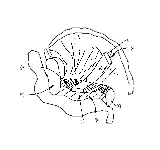
remainder of it through the tongue in the direction of the arrow in Fig. 17e
so that it exits outside
the mylohyoid muscle.
[0083] Both ends of the ribbon-like element are then pulled through the
holes in the solid
anchor of the first implant and the first implant is slid over both ends of
the ribbon-like element
until it lies against the mylohyoid muscle.
[0084] The first implant 1200 is then secured to the mylohyoid muscle and
surrounding
tissue near the mandible with sutures (preferably Vicryl Plus sutures, size 3-
0 or 4-0,
manufactured and sold by Ethicon, Inc. of Somerville, NJ) using a continuous
suture pattern.
Tension is then applied to both ends 1110 and 1112 of the ribbon-like element
to remove any
slack in the ribbon that may exist. The amount of tension placed on the ribbon-
like element and
the degree to which the base of tongue is advanced away from the posterior
pharyngeal is
determined by the surgeon and is typically based on patient anatomy, severity
of disease, and
surgeon experience.
[0085] The ends 1110, 1112 of the ribbon-like element 1105 are then secured
against the
anchor by any suitable means, such as by knotting the ends together as shown
in Fig. 17f. Any
excess is then cut away and discarded. The subcutaneous tissue and skin are
then closed with
CA 02745146 2011-05-30
WO 2010/065341 PCT/US2009/065293
suture (preferably Monocry10 suture, size 3-0 or 2-0, also manufactured and
sold by Ethicon,
Inc.). The skin is closed with a Monocryl Suture (size 3-0 or 4-0), and
possibly also a
cyanoacrylate adhesive.
[0086] FIG. 14 illustrates the position of the implant system 1100
following the surgical
procedure described above. The ribbon-like element 1401 is shown in the tongue
T of the
patient, with a central portion 1402 positioned several millimeters below the
mucosa MU of the
tongue base TB. The geometric dimensions of the central portion 1402
preferably do not differ
substantially from geometric dimensions of the remainder of its length. As
illustrated, the
ribbon-like element extends down through the tongue T and is passed through
the holes 1404
placed in the first implant 1405 located on the surface of the mylohyoid
muscle MH. In this
particular illustration, the ends 1110, 1112 of the loop 1404 are attached to
one another by
knotting. Other means for attaching the ends of the loop to the first implant
are stapling,
crimping, welding, and gluing.
[0087] The surgeon may choose to apply a certain amount of tension on the
ribbon-like
element that is based on the surgeon experience, the patient anatomy, and the
severity of the
apnea. If there is a need to adjust the tension following surgery, the surgeon
can create a small
incision in the skin beneath the jaw to expose the knotted portion of the
ribbon-like element.
The knot can be untied and the tension reset by knotting again at the desired
tension or using
clips, staples or the like to connect the ends of the ribbon-like element.
Figs. 18a-b illustrate a
small washer 1801 preferably made from a material similar to the anchor 1802
that can be slid
underneath the knot to increase tension. The increase in tension will result
in the base of the
tongue being pulled further away from the posterior pharyngeal wall. The
washer preferably has
a thickness of about 1-5 mm, and at least one opening 1803 therein within
which the ends of the
ribbon-like element may be received. One or more of these washers can be added
to the kit or
can be acquired separately. In another embodiment shown in Fig. 19, a small
balloon or the like
1901 can be placed between the knot and the anchor 1902. The volume of the
balloon, and
therefore the tension on the implant element, can be adjusted by transdermally
injecting the
balloon with sterile saline, water, or other biocompatible fluid after
implantation. Alternatively, a
separate reservoir 1905 can be injected, which may be a distance of 1-10 cm
away from the
balloon 1901 itself. The reservoir 1905 is fluidly coupled to the balloon 1901
by a tube 1906
21
CA 02745146 2011-05-30
WO 2010/065341 PCT/US2009/065293
that preferably has a one-way valve in it so as to maintain pressure in the
balloon. In this
manner, an incision would not have to be made to adjust tension on the ribbon-
like element. If
necessary, the filling reservoir 1905 can be squeezed or pressed by the
patient or physician to
drive fluid into the balloon 1901.
[0088] Techniques well known to those skilled in the art may also be used
for forming scar
tissue in the inframandibular region, such as laser energy, heat energy, or a
sclerosing agent.
An implant such as a tongue implant may be coupled with the scar tissue for
shifting the position
of the tongue for minimizing OSA events. A hyoid bone may also be coupled with
the scar
tissue using one or more elongated elements such as a tether.
[0089] The devices described above provide a number of advantages over
prior art
methods and devices used for treating obstructive sleep apnea syndrome and
hypopnea. First,
the systems, devices and methods disclosed herein provide simple surgical
procedures that are
minimally invasive that typically may be utilized during an outpatient
procedure. In addition, the
systems, devices and methods disclosed herein provide both immediate and long
term results
for treating obstructive sleep apnea syndrome and hypopnea, and do not require
a significant
level of patient compliance.
[0090] Significantly, the devices and methods described herein do not
anchor the posterior
aspect of the tongue to a fixed, hard structure. Rather, a "soft anchor" is
used in the
inframandibular region, which is significantly less likely to affect
swallowing or speech, thereby
providing a great improvement over prior art devices, systems and methods. The
above-
described devices also avoid the "cheese-cutter" effect found with prior art
implants by teaching,
inter alia, the use of a soft anchor in the inframandibular region and a
buttress for the tongue
implant. These devices also preferably use materials having long-term
biocompatibility.
[0091] Although various embodiments disclosed herein relate to use in
humans, it is
contemplated that the present invention may be used in all mammals, and in all
animals having
air passages. Moreover, the systems, devices, and methods disclosed herein may
incorporate
any materials that are biocompatible, as well as any solutions or components
that minimize
rejection, enhance tissue ingrowth, enhance the formation of mucosal layers,
and improve
acceptance of the device by a body after the device has been implanted.
22
CA 02745146 2011-05-30
WO 2010/065341 PCT/US2009/065293
[0092] The headings used herein are for organizational purposes only and
are not meant to
be used to limit the scope of the description or the claims. As used
throughout this application,
the word "may" is used in a permissive sense (i.e., meaning having the
potential to), rather than
the mandatory sense (i.e., meaning must). Similarly, the words "include",
"including", and
"includes" mean including but not limited to. To facilitate understanding,
like reference numerals
have been used, where possible, to designate like elements common to the
figures.
[0093] While the foregoing is directed to embodiments of the present
invention, other and
further embodiments of the invention may be devised without departing from the
basic scope
thereof. As such, the scope of the present invention is to be limited only as
set forth in the
appended claims.
23