Note: Descriptions are shown in the official language in which they were submitted.
CA 02745585 2012-06-18
BICYCLE STEERING/ BALANCING DEVICE
BACKGROUND OF THE INVENTION
The present invention relates generally to, but not limited to, a bicycle
rider training device, and more
particularly, to a steering/ balance control bar system to aid in training the
novice to ride a two-wheeled
bicycle. Without the aid of a rider training device, the handler is required
to assume an awkward bending
position to support the novice bike rider. Usually the handler has to bend
over to grip the novice rider or some
portion of the bike, usually the seat. Also the handler must have one hand on
the handle bar in order to steer
the bike. This while jogging along-side the bicycle in order to give the
novice bike rider the experience and
sensation of riding the bicycle.
The awkward bending position may cause several problems to develop for the
handier who is assisting in the
learning process. Back strain limits the handier's time and ability to assist
as the bent-over position also
increases the risk of stumbling while trying to jog along-side the rider. The
result, learning to ride a two-
wheeled device/ bicycle without an appropriate bicycle steering/ balancing
device and a helmet may be very
hazardous for both the novice rider and handier.
The control exerted by the handler while in the awkward bending position
substantially limits the beginners'
ability to guide the bike, increasing the time spent to overcome the fear of
tipping and falling.
Various bicycle training devices have been offered as a solution to some or
all of the above -mentioned
problems. Generally, the earlier designs comprise of one or all of the
following features: (1) a mounting
mechanism for a pole comprised of two plates which are compressed together by
a single bolt; (2) a mounting
mechanism for a pole which is not adapted to fit various widths of forks; (3)
a mounting mechanism that
utilizes a seat tube as an attachment point for a stabilizing bar; (4) a pole
which is attached to the mounting
mechanism by threaded extensions; (5) a flexible pole attached to the rear of
the bicycle; (6) a pole attached
to the rear of the bicycle that is too short for the handler to visually
monitor the side-to-side vertical motion
of the pole; (7) a pole attached to the rear of the bike which is not
vertically oriented; (8) a pole attached to the
rear of the bicycle which extends beyond the rear axle of the bicycle. The
earlier designs, however, are
inadequate for at least one of several reasons.
The mounting mechanisms of earlier designs have several shortcomings. For
instance, a mounting
mechanism for a pole comprised of two plates which are compressed together by
a single bolt is unsafe. Any
loosening of the single bolt could allow the sudden and total release of the
mounting mechanism from the
bicycle- On the other hand, a mounting mechanism that utilizes the seat tube
as an attachment point for a
stabilizing bar prevents the seat from being placed in its lowest position.
Finally, a mounting mechanism for a
pole which is not adapted to fit varying widths of forks does not allow for
mounting on various sizes of bicycle
frames.
The poles of earlier designs are also inadequate. For example, a pole which is
attached to the mounting
mechanism by threaded extensions is impractical for configuring the pole
around the seat, since any
CA 02745585 2012-06-18
stabilizing force applied to the hand grip may unscrew the clamp. On the other
hand, a flexible pole attached
to the rear of the bicycle does not give the handier sufficient control over
the bicycle. As a result, a flexible
pole makes it very difficult for the handier to securely stabilize a child who
is leaning too far or in the wrong
direction. A pole attached to the rear of the bicycle which is not vertically
oriented presents a risk of injury to
the handler should the rider stop abruptly. A pole attached to the rear of the
bicycle which extends beyond the
rear axle of the bicycle may cause the bicycle to jack-knife. A jack-knife may
occur because a force applied to
the pole beyond the rear axle creates a moment around the rear tire where the
rear tire contacts the ground.
The moment around the rear tire may then cause a lateral motion of the front
wheel and a sudden jack-knife
rotation of the handle bar.
It is, therefore, an object of the present invention to over-come the known
shortcomings of known bicycle
training devices. It is an object of the present invention to instill
confidence in the minds of the beginning
riders to allow them to believe they will not fall. It is an object of the
present invention to allow the novice to
experience the feeling of leaning into a turn. It is another object of the
present invention to provide a
balancing/ steering training device that allows the handler to safely, and in
more comfort, assist the learning
process. It is another object of the present invention to allow the handier
to, in addition to jogging beside the
rider, also stand still as the rider circles around the assistant in either
direction. It is another object of the
present invention to provide a balancing/ steering training device which is
adapted to fit onto the majority of
the most commonly used two- wheeled bicycles, vehicles and tricycles. It is
another object of the present
invention to provide a balancing /steering training device that isolates
skills to independently balance while
starting and stopping forward motion while pedaling.
It is another object of the present invention to provide a balancing /steering
training device that isolates skills
to independently balance while steering and starting and stopping the bicycle.
It is another object of the
present invention to provide a balancing/ steering training device that
isolates skills to independently balance
while steering, starting, and stopping and then combine those skills so as to
gain independence from the
handler under controlled conditions. It is another object of the present
invention to provide a
balancing /steering training device that isolates skills to independently
balance while steering, starting and
stopping, and prevents loss of control, loss of contact with the handler, and
the dreaded downhill or runaway
situations. It is another object of the present invention to provide a
balancing /steering training device that
isolates skills to independently balance while removing/ controlling the
steering action with the vertical jointed
training bar, allowing the whole bar to steer while still allowing a side to
side tipping movement of the bicycle.
It is another object of the present invention to provide a balancing /steering
training device that isolates skills
to Independently balance while adding steering to the control of the balance,
by changing the joint to allow It
to function both in the vertical and horizontal planes simultaneously.
CA 02745585 2012-06-18
SUMMARY OF THE INVENTION
The present invention is directed to a vehicle having a training support
device. A preferred embodiment of
the bicycle generally comprises: a rear wheel fork and a front wheel fork with
handle bars; and a jointed
training steering/ balancing bar attached to handlebars with u-bolts/clamps.
The present invention assists a
rider learning to ride, but not limited to, a two wheeled bicycle. The jointed
steering/ balancing arm allows the
handier a comfortable means of steering and balancing the rider who is then
going in a circle around the
handier, eliminating the need to walk or jog along-side while assisting.
The features and benefits of the present invention in its many embodiments
include:
I) Location of handier's grip - The shape of the elongate jointed pole, one
end piece mounted to
handlebars by u-bolts, places the assistant's hand grip on the hinged pole at
ninety degrees to the
direction of travel of the bicycle, the hinge allowing for variable height at
grip point.
2) Position of the joint - By creating a joint between the handier and the
handle bars, the control over
steering at the beginning of training, because the joint will only flex in the
vertical plane, allows the
handier to still exert lateral influence. This desired lateral movement aids
in vertical balancing on the
line of travel, while removing the steering risk of jack-knifing. As the rider
skills increase, controlling
the steering can then be changed by moving the joint into the horizontal-
vertical combination which
allows for both lateral and steering forces to be applied simultaneously.
3) The position of the handler - By positioning the handier at the end of the
jointed pole in the center of
the circle, guidance/steering) balance is provided from a stationary position
as the rider provides
propulsion on a circular trajectory around the handier. Walking or jogging
along-side is now an option,
not a requirement.
4) Rigid attachment of arm - The sectional arm is attached to the handlebars
by two u-clamps or other
configuration to form a rigid section with the handlebar and the joint and an
extension beyond the
joint. The joint is a common universal joint with a lockable position to limit
horizontal motion around
the joint.
5) Rigidity of design - Some earlier designs "highlight" their feature of
offering a "flexible" pole. The
trainee, in order to concentrate on learning to ride, must feel security in
the hands of the trainer. A
flexible pole makes it very difficult to securely stabilize a child who is
leaning too far, or leaning the
wrong way. The pole and mount design must be rigid, except for the u-joint, to
assert positive control
over the rider.
6) Dual U-bolt clamping - Two (2) independent U-bolts provide an extra. degree
of safety and security
over earlier designs that rely on a single bolt to provide compression and
clamping. In these earlier
designs, any loosening of the single bolt could allow a sudden and total
release of the clamp from the
bicycle frame.
CA 02745585 2012-06-18
7) Mount is independent of, and unrelated to seat height - Some earlier
designs utilize the seat tube as an
attachment point for a stabilizing bar. This method of attachment usually
prohibits the seat from being
placed in its lowest position, which would allow riders to reach the ground
with their feet when they
stop.
8) Variable horizontal orientation of the arm - The joint allows the handler
to raise or lower the arm at the
center of the circle to any desirable height. Standing at the center of the
circular trajectory makes it
safe for handier, with no adverse affects from abrupt stops by rider occurring
at the outside of circle
away from center handler position. The mounting position on the handlebars
allows a position 90
[ninety degrees] to direction of travel, the extension to the movable joint
causing maximum leverage
for supporting trainee's weight.
9) Visual and tactile feel of bar The center position away from the rider
allows for visual observation of
the rider' side-to-side motion [vertical). The bar's motion represents the
amplified feeling of the
trainee's motion, allowing the handier to react to that feeling and provide
assistance when needed in
most timely reaction.
10) A Lockable u-joint - A pin and yoke U-joint locked by sliding cross inside
pipe, in vertical plane only
which, allowing one pin to be removed and arm extended to next hole, then
allows movement in both
horizontal and vertical planes.
In addition to the novel features and advantages mentioned above, other
objects and advantages of the
present invention will be readily apparent from the following descriptions of
the drawings and
preferred embodiments.
CA 02745585 2012-06-18
BRIEF DESCRIPTION OF DRAWINGS
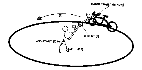
FIG. 1 is a side elevation of a preferred embodiment of a bicycle bearing a
steering/ balancing jointed
guiding arm and the location of the assistant at center of the circle.
FIG. 2 is a top view showing the position of the jointed control arm attached
to handle bar points and
showing the horizontal steering axis.
FIG. 3 is a perspective view showing the steering/ balancing arm and the
lateral influence on the
vertical balancing axis.
FIG. 4 is a perspective view of the locked U-joint with vertical only by
sliding the locking slide cross in,
and horizontal /vertical positioning between the fixed handlebar section and
the movable handler
section along with T or D end point configuration.
FIG. 5 is a side elevation view of the lockable sliding cross of the U-joint
which by sliding in or out
allows for a repositioning from vertical only movement of end section to
vertical and horizontal
movement simultaneously.
FIG. 6 is a representation of sliding flexible U-joint cover/grip.
FIG. 7 presents the location of U-clamps relating to U-joint, movable handle,
coupler, extension
handle, and D handle along with expanded view of lockable sliding cross.
CA 02745585 2012-06-18
DETAILED DESRIPTION OF THE EMBODIMENT
The present invention is directed to, but is not limited to, a bicycle bearing
a steering/ balancing arm
training device.
FIG.1 is a side elevated view of a preferred embodiment of the present
invention. A preferred
embodiment of a bicycle generally comprises: a rear wheel fork, wheel and
axle, a front wheel fork, a
wheel and axle and commonly a seat and handlebars [1 5] above the axle- As
shown in FIG.2, the
steering /balancing device [1 ], is mounted rigidly to the handlebars (15]
using clamps, straps or other
fixtures [4].
As shown in FIG. 1 , an assistant [7] is positioned at the center of the
circular trajectory [6] and
holds extension handle [2] including a D or 'I- or various grips, inside the
lockable U-joint [3].
In the first starting position of the locking U-joint [3], the pins are placed
in the arrangement [Hole
AA and Hole BR] by sliding the lockable cross inside the pipe, allowing only
vertical movement at the
U-joint [3] of the extension handle [2].
In the second positioning of the pins [Hole AA and Hole CC], at the U-joint
[31, the movement at the
U-joint is then allowed in both the vertical balancing axis [8] and horizontal
steering axis [9] planes.
As shown in FIG.3, all pin positions allow the vertical balancing axis [8] to
be controlled always.
By locking the horizontal steering axis [9] at the joint, the steering or
movement of horizontal
steering axis [9] is influenced by the whole control arm from the end-point
at the center [10] to the axis in the handlebars at 11 Oa],
As shown in FIG.4, the first position [Hole AA and Hole 80] of the lockable
sliding cross and pins of
the locking ujoint, allow for vertical rotation only of the steering
/balancing device.
As shown in FIG.5, by changing the pin placement to the second position [Hole
AA and Hole CC]1
rotation of both vertical balancing axis [8] and horizontal steering axis [9]
occurs simultaneously.
As shown in Fig. 6, a flexible U-joint cover [6] prevents external mechanical
interference of U.-joint
[3].
The preferred embodiments herein disclosed are not intended to be exhaustive
or to unnecessarily
limit the scope of the invention. 1 "he preferred embodiments were chosen and
described in order to
explain the principles of the present invention, so that others skilled in the
art may practice the
invention. Having shown and described preferred embodiments of the present
invention, those skilled
in the art will realize that many variations and modifications may be made to
affect the described
CA 02745585 2012-06-18
invention. Many of these variations and modifications will provide the same
result and fall within the
spirit of the claimed invention. It is the intention therefore, to limit the
invention only as indicated by
the scope of the claims: