Note: Descriptions are shown in the official language in which they were submitted.
CA 02745602 2011-07-07
ACTUATOR ASSEMBLY AND ELECTRONIC DEVICE INCLUDING SAME
FIELD OF TECHNOLOGY
[0001] The present disclosure relates to an actuator assembly for providing
tactile
feedback in an electronic device that includes a touch-sensitive input device.
BACKGROUND
[0002] Electronic devices, including portable electronic devices, have
gained
widespread use and may provide a variety of functions including, for example,
telephonic,
electronic text messaging and other personal information manager (PIM)
application
functions. Portable electronic devices can include several types of devices
including
mobile stations such as simple cellular tphones, smart phones, Personal
Digital
Assistants (PDAs), and laptop computers.
[0003] Devices such as PDAs or smart phones are generally intended for
handheld
use and ease of portability. Smaller devices are generally desirable for
portability. Touch-
sensitive devices constructed of a display, such as a liquid crystal display
(LCD), with a
touch-sensitive overlay are useful on such handheld devices as such handheld
devices
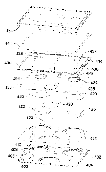
are small and are therefore limited in space available for user input and
output devices.
Further, the screen content on the touch-sensitive devices can be modified
depending on
the functions and operations being performed.
[0004] Tactile feedback for such touch-sensitive input devices provides a
positive
confirmation of, for example, touch selection. The provision and control of
tactile
feedback in touch-sensitive devices is desirable.
SUMMARY
[0005] An actuator assembly for use in an electronic device. The actuator
assembly
includes a support tray, an actuator supported on the support tray, and a
cover over the
actuator and coupled to the support tray, a portion of the cover being movable
relative to
the support tray when the actuator is actuated.
[0006] An electronic device includes a housing, a touch-sensitive input
device
exposed by the housing, and an actuator assembly. The actuator assembly is
housed in
the housing and coupled to the touch-sensitive input device.
- 1 -
CA 02745602 2011-07-07
BRIEF DESCRIPTION OF THE DRAWINGS
[0007] Embodiments of the present disclosure will now be described, by way
of
example only, with reference to the attached Figures, wherein:
[0008] FIG. 1 is a simplified block diagram of components including
internal
components of a portable electronic device according to an example embodiment;
[0009] FIG. 2 is a perspective view of an example of a portable electronic
device;
[0010] FIG. 3 is an exploded view of portions of the portable electronic
device of FIG.
2, including an actuator assembly in accordance with an example embodiment;
[0011] FIG. 4A is a perspective view of an actuator assembly for use in an
electronic
device, according to an example embodiment;
[0012] FIG. 4B is a rear view of the actuator assembly of FIG. 4A;
[0013] FIG. 4C is a sectional view through the line 4C-4C of FIG. 4B;
[0014] FIG. 5 is an exploded view of the actuator assembly of FIG. 4A;
[0015] FIG. 6 is an exploded view of the actuator assembly of FIG. 4A and a
touch-
sensitive display; and
[0016] FIG. 7 is a sectional view through the line 7-7 of FIG. 2.
DETAILED DESCRIPTION
[0017] The following describes an actuator assembly for use in an
electronic device.
The actuator assembly includes a support tray, an actuator supported on the
support tray,
and a cover over the actuator and coupled to the support tray. A portion of
the cover is
movable relative to the support tray when the actuator is actuated.
[0018] It will be appreciated that for simplicity and clarity of
illustration, where
considered appropriate, reference numerals may be repeated among the figures
to
indicate corresponding or analogous elements. In addition, numerous specific
details are
set forth in order to provide a thorough understanding of the example
embodiments
described herein. However, it will be understood by those of ordinary skill in
the art that
the example embodiments described herein may be practiced without these
specific
details. In other instances, well-known methods, procedures and components
have not
been described in detail so as not to obscure the example embodiments
described
- 2 -
CA 02745602 2013-07-09
herein. Also, the description is not to be considered as limited to the scope
of the
example embodiments described herein.
[0019] Example embodiments of the actuator assembly described herein are
adapted
for use in an electronic device such as a portable electronic device that
includes a touch-
sensitive display. FIG. 1 shows a simplified block diagram of components
including
internal components of a portable electronic device according to an example
embodiment.
[0020] The portable electronic device 100 includes multiple components such
as a
processor 102 that controls the operations of the portable electronic device
100.
Communication functions, including data and voice communications, are
performed
through a communication subsystem 104. Data received by the portable
electronic
device 100 is decompressed and decrypted by a decoder 106. The communication
subsystem 104 receives messages from and sends messages to a wireless network
150.
The wireless network 150 may be any type of wireless network, including, but
not limited
to, data-centric wireless networks, voice-centric wireless networks, and dual-
mode
networks that support both voice and data communications over the same
physical base
stations. The portable electronic device 100 is a battery-powered device and
includes a
battery interface 142 for receiving one or more rechargeable batteries 144.
[0021] The processor 102 also interacts with additional subsystems such as
a
Random Access Memory (RAM) 108, a flash memory 110, a display 112 with a touch-
sensitive overlay 114 connected to an electronic controller 116 that together
comprise a
touch-sensitive display 118, actuators 120, one or more force sensors 122, an
auxiliary
input/output (I/O) subsystem 124, a data port 126, a speaker 128, a microphone
130,
short-range communications 132 and other device subsystems 134. User-
interaction with
the graphical user interface is performed through the touch-sensitive overlay
114. The
processor 102 interacts with the touch-sensitive overlay 114 via the
electronic controller
116. Information, such as text, characters, symbols, images, icons, and other
items that
may be displayed or rendered on a portable electronic device, is displayed on
the touch-
sensitive display 118 via the processor 102. The processor 102 may also
interact with an
accelerometer 136 as shown in FIG. 1. The accelerometer 136 may include a
cantilever
beam with a proof mass and suitable deflection sensing circuitry. The
accelerometer 136
may be utilized for detecting direction of gravitational forces or gravity-
induced reaction
forces.
[0022] To identify a subscriber for network access according to the present
- 3 -
CA 02745602 2013-07-09
embodiment, the portable electronic device 100 uses a Subscriber Identity
Module or a
Removable User Identity Module (SIM/RUIM) card 138 inserted into a SIM/RUIM
interface 140 for communication with a network such as the wireless network
150.
Alternatively, user identification information may be programmed into the
flash memory
110.
[0023] The portable electronic device 100 also includes an operating system
146 and
software components 148 that are executed by the processor 102 and are
typically stored
in a persistent store such as the flash memory 110. Additional applications
may be
loaded onto the portable electronic device 100 through the wireless network
150, the
auxiliary I/O subsystem 124, the data port 126, the short-range communications
subsystem 132, or any other suitable device subsystem 134.
[0024] In use, a received signal such as a text message, an e-mail message,
or web
page download is processed by the communication subsystem 104 and input to the
processor 102. The processor 102 then processes the received signal for output
to the
display 112 or alternatively to the auxiliary I/O subsystem 124. A subscriber
may also
compose data items, such as e-mail messages, for example, which may be
transmitted
over the wireless network 150 through the communication subsystem 104. For
voice
communications, the overall operation of the portable electronic device 100 is
similar.
The speaker 128 outputs audible information converted from electrical signals,
and the
microphone 130 converts audible information into electrical signals for
processing.
[0025] FIG. 2 is a perspective view of an example of a portable electronic
device 100.
The portable electronic device 100 includes a housing 202 that is suitable for
housing the
internal components shown in FIG. 1. The housing includes a frame 204 that
frames the
touch-sensitive display 118 for user-interaction with the touch-sensitive
display 118.
Although not shown in the figures, the portable electronic device 100 of FIG.
2 can further
include a physical keyboard (not shown) such that the processor 102 (shown in
FIG 1)
interacts with the keyboard and the housing 202 is constructed to accommodate
the keys
of the keyboard.
[0026] FIG. 3 is an exploded view of portions of the portable electronic
device 100
including an actuator assembly 300. The housing 202 of the portable electronic
device
100 includes a front 302 that includes the frame 204 and the back 304. As
shown, the
back 304 of the housing 202 includes an opening that may be covered by a plate
that is
releasably attachable to the back 304 for insertion and removal of, for
example, the
SIM/RUIM card 138. In the example of FIG 3, the battery 144 is shown along
with a
- 4 -
CA 02745602 2013-07-09
. .
printed circuit board 306. The touch-sensitive display 118 is disposed on the
actuator
assembly 300 and is available for user interaction through an opening defined
by frame
204 in the front 302 of the housing 204.
[0027] Referring now to FIG. 4A, FIG. 4B, FIG 4C and FIG. 5, these figures
show
various views of the actuator assembly 300. In the presently described example
embodiment, the actuator assembly 300 includes three actuators 120, which in
the
present embodiment are piezoelectric disk actuators. Different numbers of
actuators 120
are used in other embodiments. The actuators 120 are supported by a support
tray 402
that is generally rectangular in shape. The support tray 402 includes a
generally flat
portion 403 with a lip 404 that protrudes from one side and extends generally
around flat
portion 403. The lip 404 extends only partly around the flat portion 403 as a
break in the
lip 404 is provided at each side of the support tray 402. The breaks in the
lip 404, which
may be cut-out portions, are optional. These breaks may be added to increase
flexibility
of the actuator sheet. Alternatively, the actuator sheet can be without breaks
in the lip for
sealing the actuator assembly. Three pockets 406 are provided in the support
tray 402
and each pocket 406 supports a respective one of the actuators 120 while
facilitating
movement in the form of actuation of the actuators 120. Each pocket 406
includes a step
such that an annular ledge 408 is located around an inner circular depression
410. The
annular ledge 408 is recessed from the flat portion 403 to provide a seat for
the
respective actuator 120 and the inner circular depression 410 provides a
spacing
between the actuator 120 and the support tray 402. The support tray 402 may be
formed
of metal such as stainless steel.
[0028] Reference is now made to FIG. 4C and to FIG 5 which show a sectional
view
and an exploded view of the actuator assembly 300. A non-conductive tape 412
is
disposed on the support tray 402. The non-conductive tape 412 is adhered to
both the
support tray 402 and the actuators 120 and electrically isolates the actuators
120 from the
support tray 402. In the present example, the non-conductive tape 412 covers
the entire
support tray 402 with the exception of the inner circular depression 410 of
each pocket
406. Thus, the non-conductive tape 412 covers the generally flat portion 403
and the
annular ledge 408 of the support tray 402.
[0029] Each actuator 120 includes a piezoelectric disk such as a PZT
ceramic disk
414 adhered to a metal substrate 416 of larger diameter than the piezoelectric
disk 414
for bending when the piezoelectric disk 414 contracts diametrically as a
result of build up
of charge at the piezoelectric disk 414. The metal substrate 416 of the
actuator 120 is
- 5 -
CA 02745602 2013-07-09
supported on the annular ledge 408 with the non-conductive tape 412,
electrically
isolating the metal substrate 416 and the piezoelectric disk 414 from the
support tray 402.
The piezoelectric disk 414 is located in the circular depression 410 and
spaced from the
support tray 402 by a non-conductive cushion 418 for electrically isolating
the actuator
120.
[0030] A ring of conductive tape 420 is adhered to the piezoelectric disk
414 of each
actuator 120 and to a flexible printed circuit board 422. The flexible printed
circuit board
422 includes conductive traces that are electrically connected to the
piezoelectric disks
414 to connect the actuators 120 to, for example, the printed circuit board
306 of the
portable electronic device 100. The flexible printed circuit board 422 also
includes C-
shaped cut-outs, with each C-shaped cut-out corresponding to a respective
actuator 120
such that, at each actuator 120, a generally circular member 424 is connected
by a web
portion 426 to a remainder 428 of the flexible printed circuit board 422. The
web portion
426 facilitates further flexing of the generally circular member 424 relative
to the
remainder 428 of the flexible printed circuit board 422.
[0031] Still referring to FIG. 5, an actuator sheet 430 acts as a cover to
cover the
flexible printed circuit board 422 and the actuators 120 and is coupled to the
support tray
402. The actuator sheet 430 includes a generally rectangular inner sheet 432
inset in a
larger rectangular outer ring 434. The inner sheet 432 is spaced from the
rectangular
outer ring 434 by an intermediate gap. The intermediate gap is interrupted by
resiliently
flexible arms 436 that join the inner sheet 432 to the outer ring 434. The
arms 434 form a
jog, such that the location at which one of the arms 434 joins the inner sheet
432 is offset
from alignment with the location that the arm 434 joins the outer ring 434, to
facilitate
movement of the inner sheet 432 relative to the outer ring 434. The inner
sheet 432,
outer ring 434 and resiliently flexible arms 436 may be integral portions of a
sheet and
may be formed by cutting away portions to form the intermediate gap.
[0032] The inner sheet 432 includes protrusions 438 formed therein with a
respective
protrusion 438 extending from the inner sheet 432 toward each actuator 120
such that
each protrusion 438 abuts a respective circular member 424 that abuts a
respective
actuator 120. In the present example, the actuator sheet 430 is a metal sheet
of, for
example, spring steel to facilitate grounding of the touch-sensitive display
118 that is
disposed on the actuator sheet 430. The outer ring 434 is coupled to the
support tray 402
by, for example, spot welding the outer ring 434 to the lip 404 of the support
tray 402.
Alternatively, the actuator sheet 430 may form a mechanical interlock with the
support
- 6 -
CA 02745602 2013-07-09
. .
tray 402. The inner sheet 432 is movable relative to the outer ring 434 and
the support
tray 402 when the actuators 120 are actuated. The actuator sheet 430
facilitates pre-
loading of the actuators 120 and thus, preloading of the actuator assembly 300
during
production of the actuator assembly 300 such that a bending force acts on the
actuators
120, and the actuators 120 provide a spring force in return, when the
actuators 120 are
not charged and the actuator assembly 300 is in a rest position.
[0033] A gasket 440 is disposed on the actuator sheet 430, on the outer
ring 434 and
a sealing element 450 is disposed on the gasket 440 for creating a seal with
the housing
202 of the portable electronic device 100. The gasket 440 may include an
adhesive on
one side and is flexible to facilitate the spring function of the actuator
sheet 430 and to
seal the actuator assembly 300.
[0034] FIG. 6 is an exploded view of the actuator assembly with a touch-
sensitive
display 118. The touch-sensitive display 118 is an assembly of components
including the
LCD display 112, the overlay 114 and controller 116 (shown in FIG. 1). The
touch-
sensitive display 118 is coupled to the inner sheet 432.
[0035] The touch-sensitive display 118 may be a capacitive touch-sensitive
display,
for example and a user's touch on the touch-sensitive display may be
determined by
determining the X and Y location of the touch, with the X location determined
by a signal
generated as a result of capacitive coupling with a touch sensor layer and the
Y location .
determined by the signal generated as a result of capacitive coupling with
another touch
sensor layer. Each of the touch-sensor layers provides a signal to the
controller 36 that
represents the respective X and Y touch location values. Thus a feature such
as a virtual
button or other feature displayed on the touch-sensitive display 118 may be
selected by a
mapping of the touch location to a feature on the touch-sensitive display 118.
[0036] FIG. 7 is a sectional view through the line 7-7 of FIG. 2. As shown,
the
actuator assembly 300 is disposed in the portable electronic device 100,
between the
touch-sensitive display 118 and a base 702. The base 702 is generally rigidly
supported
within the portable electronic device 100 and provides a base 702 for the
support tray
402. Alternatively, the support tray 402 may be included in the portable
electronic device
without the base. When a base is not provided, the support tray may be formed
with
features such as ribs or corrugations to increase rigidity.
[0037] The actuator assembly 300 acts on the touch-sensitive display 118
such that
when the actuators 120 are actuated, a force is transmitted from the actuators
120,
- 7 -
CA 02745602 2013-07-09
, .
through the actuator sheet 430 and to the touch-sensitive display 118, to move
the touch-
sensitive display 118 relative to the base 702 and the back 304 of the housing
202 of the
portable electronic device 100.
[0038] A charge applied to the piezoelectric disks 414 of the actuators 120
results in
the piezoelectric disk 414 shrinking diametrically, causing the metal
substrate 416 and
therefore the entire actuator 120, to bend and apply a force to the inner
sheet 432 of the
actuator sheet 430. Because the inner sheet 432 is moveable relative to the
support tray
402, the inner sheet 432 is moved away from the support tray 402 as the
resiliently
flexible arms 436 are flexed. The touch-sensitive display 118 is thereby moved
away
from the support tray 402, and thus, away from the back 304 of the housing 202
of the
portable electronic device 100. The removal of the charge, causes the
actuators 120 to
return to the rest position and the resiliently flexible arms 436 facilitate
movement of the
inner sheet 432 to return to the rest position. Thus, the touch-sensitive
display 18 is
moved back to the rest position. The actuators 120 are connected through the
flexible
printed circuit board 416 to, for example, the printed circuit board 306 of
the portable
electronic device 100 and may be controlled by drive circuitry connected to
the processor
102 or other microprocessor.
[0039] The mechanical work performed by the actuators 120 may be controlled
to
control the force and movement of the touch-sensitive display 118, for
example, in
response to detection of a touch. Alternatively, force sensors may be included
as part of
the actuator assembly 300 or external to the actuator assembly to measure an
applied
force by a user touch on the touch-sensitive display 118 and the actuators 120
may be
controlled to provide movement of the touch-sensitive display 118 in response
to
detection of an applied force on the touch-sensitive display 118. Fluctuations
in
mechanical work performed as a result of, for example, temperature, may be
reduced by
modulating the current to the actuators 120 to control the charge. An increase
in the
charge increases the force on the touch-sensitive display 118 away from the
support tray
402 and a decrease in the charge decreases the force on the touch-sensitive
display 118,
facilitating movement of the touch-sensitive display 118 toward the base 82.
In the
present example embodiment, each of the actuators 120 is controlled equally
and
concurrently. It will be appreciated that the piezoelectric actuators can be
controlled
separately, however. The portable electronic device 100 is controlled
generally by
modulating a force on the touch-sensitive display 118 to cause movement of the
touch-
sensitive display 118 relative to the support tray 402 of the portable
electronic device 100
- 8 -
CA 02745602 2013-07-09
-
in response to detection of a touch.
[0040] The embodiments shown and described herein illustrate examples only
and
many modifications may be made. For example, the number of actuators may
differ. In
one example, four actuators are located near respective corners of the
actuator assembly.
[0041] The actuator assembly provides a relatively thin device to provide
desirable
tactile feedback, for example, to simulate actuation of a dome switch upon
touching the
touch-sensitive display, confirming receipt of input to the user. The tactile
feedback
provides a positive response and reduces the chance of input errors such as
double
entry, decreasing use time and increasing user-satisfaction. Further, the
actuator
assembly includes a metal actuator sheet that facilitates grounding of the
touch-sensitive
display that is disposed on the actuator sheet. The actuator sheet facilitates
pre-loading
of the actuator assembly during production of the actuator assembly.
Furthermore, the
tolerance of the actuator assembly may be controlled to provide an assembly
with tight
tolerance as the tolerance of the entire assembly may be controlled at a lower
cost by
comparison to providing a low tolerance for all the parts individually.
[0042] While the embodiments described herein are directed to particular
implementations of the actuating assembly and the portable electronic device
and the, it
will be understood that modifications and variations may occur to those
skilled in the art.
All such modifications and variations are believed to be within the sphere and
scope of
the present disclosure.
- 9 -