Note: Descriptions are shown in the official language in which they were submitted.
CA 02745906 2013-04-16
SLEEVE FOR A CONTAINER
BACKGROUND
[0002] Hot and cold beverages (e.g., coffee, tea, soft drinks, and the
like) are
often sold in disposable drink cups for example, paper, plastic, and foam
drinking cups.
Sleeves are sometimes used in conjunction with the cup to convey information
such as
advertising, branding, or promotions or to help isolate a hand of the user
from a
temperature of the contents of the cup. A one-size sleeve, however, may not
work well
with different sized cups.
BRIEF SUMMARY
[0003] An adjustable sleeve for a container is disclosed. The sleeve
includes a
body having a top edge defining an opening, a bottom edge defining an opening,
a first
end and a second end. The first end and the second end are joined by a closure
device to
form a conical configuration of the body. The closure device permits inverse
rotation of
the first end relative to the second end which translates into an inverse
diameter change in
the opening defined by the top edge and the opening defined by the bottom
edge. The
rotation may permit the sleeve to adjust to the size and taper of many
different cups and
other containers.
[0004] Other systems, methods, features and advantages of the invention
will be,
or will become, apparent to one with skill in the art upon examination of the
following
figures and detailed description. It is intended that all such additional
systems, methods,
features and advantages be included within this description, be within the
scope of the
invention, and be protected by the following claims.
BRIEF DESCRIPTION OF THE DRAWINGS
[0005] FIG. 1 is a front view of a sleeve assembled with a container.
[0006] FIG. 2 is a view of a sleeve blank.
[0007] FIG. 3 is a view of a sleeve in a neutral state taper.
1
CA 02745906 2011-06-06
WO 2010/099090 PCT/US2010/025010
[0008] FIG. 4 is a view of a sleeve in an obtuse taper.
[0009] FIG. 5 is a view of a sleeve with an acute taper.
[0010] FIG. 6 is a view of a sleeve positioned with a container.
[0011] FIG. 7 is a first side view of a sleeve positioned with a container.
[0012] FIG. 8 is a second side view of a sleeve positioned with a
container.
DETAILED DESCRIPTION
[0013] Containers such as cups and food containers are used widely in
offices,
restaurants, cafes, convenience stores, and other establishments. The
containers may
come in a wide variety of sizes, from, for example, approximately 2oz to
approximately
32oz and larger.
[0014] An adjustable sleeve for use with a container is disclosed. The
adjustability of
the sleeve may allow one sleeve to conform to containers of varying sizes and
tapers.
Using an adjustable sleeve to convey information and/or provide thermal
insulation may,
among other attributes, have manufacturing efficiencies, may reduce waste, and
may
facilitate quick promotional strategy changes.
[0015] In FIG. 1, a sleeve 10 may be positioned with a container 12. The
sleeve 10
may be removable from the container 12, fixedly attached to the container 12
and/or
removably affixed to the container 12. The container 12 may include a base 14
end and a
rim 16 end. The container 12 may be manufactured of plastic, foam, paper, or
any other
material, and may be adapted to hold hot or cold food or beverages.
[0016] The base 14 of the container 12 may include a diameter that is
smaller than the
diameter of the rim 16 such that the side walls taper in from the open top to
the closed
base of the container 12. The taper may be designated by the taper angle Co of
a wall of
the container 12 from vertical. The taper angle Co of a container 12 may
change as a
function of the size of the container 12, for example, the taper angle Co may
be in the
range of 0=0 to 0=40 or greater. The sleeve 10 may also be used with
containers 12
that contain no taper or which have a negative taper such that the base 14 has
a diameter
larger than the rim 16.
[0017] The sleeve 10 may be combined with the container 12 such that the
sleeve 10
encircles the circumference of the container 12. The sleeve may define a first
edge 18,
such as a top edge and a second edge 20, such as a bottom edge. The first edge
18 and
2
CA 02745906 2011-06-06
WO 2010/099090 PCT/US2010/025010
the second edge 20 may be arched. The sleeve 10 may be affixed to the
container 12,
such as by friction or by adhesives such as hot-melt, fugitive or non-fugitive
glue. The
sleeve 10 may be manufactured of, for example, paperboard, cardboard, fluted
board,
plastic, foam, cellulosic fiber, white virgin paper, brown recycled paper, or
other
materials and may be recyclable or compostable. Additionally, the sleeve 10
may be, for
example, one or more layers, may have corrugation, fluting, air channels, air
pockets,
embossing, debossing, scoring , notches, slits, or etc. Scoring, notching, or
slits may lend
further adjustability to the shape of the sleeve.
[0018] The sleeve 10 may have a surface that faces the cup 12 and a surface
that faces
away from the cup 12. Either surface of the sleeve may include, for example,
graphics,
information, advertising, thermochromic features, and/or photochromic
features. For
example, the sleeve may have thermochromic features, such as graphics which
may
change colors due to a change in temperature. As another example, the sleeve
may have
photochromic features that undergo a change when they react to light. Such
features may
be useful for adapting a container to the function of, for example, providing
the
temperature of the contained material. Alternatively or additionally, a
surface may be
coated with a barrier material, for example but not limited to, wax, foam,
glues,
chemicals, dyes, or any other material that, for example, provides a
protective surface.
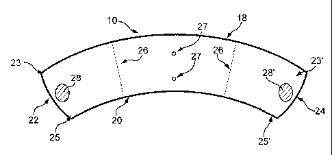
[0019] FIG. 2 illustrates a blank of an exemplary sleeve 10. The blank of
the sleeve
may include a first edge 18 and a second edge 20 of the sleeve 10, which may
be the
top and bottom of the blank, or vice versa. The blank of the sleeve 10 may
also include a
first end 22 and a second end 24. The first end 22 and second end 24 of the
sleeve blank
may include a top corner 23, 23' respectively, where the ends 22, 24 meet with
the first
edge 18 of the sleeve 10. The first end 22 and second end 24 of the blank of
the sleeve 10
may include a bottom corner 25, 25', respectively where the ends 22, 24 meet
with the
second edge 20 of the blank of the sleeve 10.
[0020] The first end 22 of the blank of the sleeve 10 may include a closure
area 28,
which may be approximately centered between the top corner 23 and the bottom
corner
25. Alternatively or additionally, the second end 24 of the sleeve 10 may
include a
closure area 28', which may be approximately centered between the top corner
23' and
the bottom corner 25'. The closure areas 28, 28' may be of any shape, for
example but
not limited to, circular, diamond, rectangular, or irregular.
3
CA 02745906 2011-06-06
WO 2010/099090 PCT/US2010/025010
[0021] Referring also to FIG. 3, the sleeve 10 may be formed by joining the
ends 22,
24 of the blank of the sleeve 10 together to form a continuous or interrupted
ring. The
ends 22, 24 of the blank of the sleeve 10 may be joined at a closure area, 28,
28' by, for
example, adhesive, a bolt/flange fastener, or any other device allowing
flexibility, such as
rotation. For example, the ends 22, 24 of the blank of the sleeve 10 may be
joined at a
closure area 28, 28' by an adhesive. The adhesive may be a fugitive glue, for
example, a
flexible or yieldable fugitive glue and/or a flexible or yieldable hot melt
adhesive (e.g.,
pressure sensitive hot melt adhesives). The adhesive may be applied to a
closure area 28,
28' and may create a pivot region 30. The adhesive may secure the ends 22, 24
while still
permitting flexibility at the pivot region Fig. 3, 30 where the ends 22, 24
are secured.
[0022] The blank of the sleeve 10 may also include perforations 26 (FIG.
2), such
that, when removed from a container 12, the sleeve 10 can be collapsed into a
flat plane
(FIGS. 3-5). Collapsing into a flat plane may permit the sleeves to be
efficiently packed
in ready-to-use form. The flat-plane form of the sleeve 10 may also provide
efficiencies
for storing, for example, on counter tops, in storage containers, in boxes, on
shelves, and
etc. The sleeve 10 may be converted from collapsed form to uncollapsed form
by, for
example, pushing inward on the fold lines created by the perforations 26 (FIG.
2).
[0023] Adhesive regions 27 (FIG.2) may be applied also to other locations
of the
sleeve such as at the vertical midline of the inside surface of the sleeve
(e.g., the surface
facing the container 12). The adhesive regions 27 (FIG. 2) may secure the
sleeve 10 to a
container 12. The adhesive region 27 (FIG. 2) may be a fugitive glue, or heat
activatable
glue, which may flex with the sleeve 10, or it may be a hot melt or any other
adhesive.
[0024] FIG. 3 illustrates the back of a sleeve 10 in a neutral (e.g.,
unflexed) and
collapsed configuration. The neutral configuration of a sleeve may differ
depending on
an implementation. The sleeve 10 may be been formed by joining the ends 22, 24
of the
sleeve 10. The ends 22 and 24 may be joined at a closure area 28, which may
create a
pivot region 30. The pivot region 30 may permit the corners 23, 23', 25, 25'
to rotate
relative to each other. For example, rotation at the pivot region 30 may
increase the
overlap distance 35 between the corners 23 and 23' while decreasing the
overlap distance
37 between the comers 25 and 25'.
[0025] The sleeve 10 may have an opening for receiving a container 12 at
the first end
31 and at the second end 33 of the sleeve 10. The sleeve 10, (e.g., when
applied to a
4
CA 02745906 2011-06-06
WO 2010/099090 PCT/US2010/025010
container) may have a diameter. For example, the sleeve 10 may have a diameter
34
which may represent the diameter 29 of the first end 31 of the sleeve 10, a
diameter 36
which may represent the diameter at or near the pivot region 30, and a
diameter 38 which
may represent the diameter at the second end 33 of the sleeve 10.
[0026] FIG. 4 illustrates the sleeve 10 that has been rotated to fit a
taper angle 0 (FIG.
1) greater than neutral. The sleeve 10 may adapt the increased taper angle 0
(FIG. 1) of a
container 12 by, for example, flexing outward. For example, as a container 12
is inserted
through a top 31 of the sleeve 10, the taper of the sleeve 10 may increase by
rotation at
the pivot region 30. Rotation of the ends 22, 24 of the sleeve 10 about the
pivot region 30
may decrease the overlap distance 35 between comers 23 and 23', which may
increase
the diameter 34. This rotation may concurrently increase the overlap distance
37 between
comers 25 and 25' which may decrease the diameter 38. The diameter 36 at or
around
the pivot region 30 may remain relatively constant throughout the rotation or
may
increase or decrease slightly (e.g., to a smaller degree than the change in 34
and 38). As
the sleeve 10 flexes outward, the pitch of the first edge 18 (FIG.1) and
second edge 20
(FIG.1) may increase or decrease.
[0027] FIG. 5 illustrates a sleeve 10 that has been rotated to fit a taper
angle 0
(FIG.1) less than neutral. The sleeve 10 may adapt the increased taper angle 0
(FIG.1) of
a container 12 by, for example, flexing inward. For example, as a container 12
is inserted
through a top 31 of the sleeve 10, the taper of the sleeve 10 may decrease by
rotation of
the sleeve about the pivot region 30. Rotation of the ends 22, 24 of the
sleeve 10 about
the pivot region 30 may increase the overlap distance 35 between corners 23
and 23',
which may decrease the diameter 34. This rotation may concurrently decrease
the
overlap distance 37 between comers 25 and 25' which may increase the diameter
38. The
diameter 36 of the pivot region 30 may remain relatively constant throughout
the rotation
or may increase or decrease slightly (e.g., to a smaller degree than the
change in 34 and
38). The diameter 36 may not be at the same location during all conformations.
However, regardless of the increase or decrease in diameters 34 and 38, a
diameter 36
will remain relatively constant. As the sleeve 10 flexes inward, the pitch of
the first edge
18 (FIG. 1) and the second edge 20 (FIG. 1) may increase or decrease.
[0028] FIG. 6 illustrates a back view of the sleeve 10 positioned with the
container 12.
This view is merely illustrative as the appearance may be altered by the state
of
CA 02745906 2011-06-06
WO 2010/099090 PCT/US2010/025010
adjustment of the sleeve 10 and the taper angle 0 (FIG.1) of the container 12.
For
example, the overlap distances 35, 37 may increase or decrease as a function
of the taper
angle 0 (FIG.1). Further, the overlap distances 35 and 37 may adjust
inversely, where as
35 increases 37 decreases and vice versa. The diameters 34, 38 may also
increase or
decrease as a function of the taper angle 0 (FIG.1). Further, the diameters 34
and 38 may
adjust inversely, for example, as diameter 34 increases diameter 38 decreases
and vice
versa.
[0029] FIGS. 7 and 8 illustrate a first side and second side view of the
sleeve 10
positioned with the container 12. This view is merely illustrative as the
appearance may
be altered by the state of adjustment of the sleeve 10 and the taper angle 0
(FIGS.1, 6) of
the container 12. For example, the first edge 18 of the sleeve 10 may form an
angle 0'
with respect to horizontal 80. Similarly, the second edge 20 of the sleeve 10
may form an
angle 0" with respect to horizontal 80. The angles 0', 0" may vary as a
function of the
state of adjustment of the sleeve 10 and the taper angle 0 (FIGS.1, 6) of the
container 12.
[0030] An adjustable sleeve for use with a container is disclosed. The
taper of the
sleeve may be adjustable such that the sleeve may fit a wide range of
containers. The
sleeve may also provide a thermal barrier between the container and a hand of
a user.
The width of the sleeve from top to bottom may approximate the width, for
example, of at
least two fingers of an adult human hand, and the shape may accommodate
placing a
thumb and at least three fingers on the sleeve.
[0031] Establishments may use the sleeve to apply information (e.g.,
information
regarding contents as well as advertising, promotions, source information,
branding, and
instructions) to containers. The information may be time sensitive or have
time limited
relevance. Accordingly, establishments relying upon containers to convey
information
may be required to frequently revolve their disposable container stock. This
may lead to
waste (throwing away of "expired" container stock) and/or delays. Reducing the
amount
of sheet material used in manufacturing protective sleeves by providing
sleeves that are
adjustable and usable with a range of containers may cause waste reduction,
which may
be better for the environment. The sleeve may be affixed to a container by
inserting the
container into the sleeve, or alternatively, wrapping the sleeve around the
container and
then affixing the ends of the sleeve together, and/or affixing the sleeve to
the container.
6
CA 02745906 2011-06-06
WO 2010/099090
PCT/US2010/025010
[0032] While various embodiments of the invention have been described, it
will be
apparent to those of ordinary skill in the art that many more embodiments and
implementations are possible that are within the scope of the invention.
7