Note: Descriptions are shown in the official language in which they were submitted.
CA 02746246 2011-06-08
WO 2010/066772 PCT/EP2009/066697
1
A SYSTEM AND METHOD FOR PROVIDING A SELF COOLING CONTAINER
Beverage cans and beverage bottles have been used for decades for storing
beverages, such as carbonated beverages, including beer, cider, sparkling
wine,
carbonated mineral water or various soft drinks, or alternatively non-
carbonated
beverages, such as non-carbonated water, milk products such as milk and
yoghurt,
wine or various fruit juices. The beverage containers, such as bottles and in
particular cans, are typically designed for accommodating a maximum amount of
beverage, while minimising the amount of material used, while still ensuring
the
mechanical stability of the beverage container.
Most beverages have an optimal serving temperature significantly below the
typical
storage temperature. Beverage containers are typically stored at room
temperatures
in supermarkets, restaurants, private homes and storage facilities.. The
optimal
consumption temperature for most beverages is around 5 C and therefore,
cooling
is needed before serving the beverage. Typically, the beverage container is
positioned in a refrigerator or a cold storage room or the like well in
advance of
serving the beverage so that the beverage may assume a temperature of about 5
C
before serving. Persons wishing to have a beverage readily available for
consumption must therefore keep their beverage stored at a low temperature
permanently. Many commercial establishments such as bars, restaurants,
supermarkets and petrol stations require constantly running refrigerators for
being
able to satisfy the customers' need of cool beverage. This may be regarded a
waste
of energy since the beverage can may have to be stored for a long time before
being consumed.
As discussed above, the cooling of beverage containers by means of
refrigeration is
very slow and constitutes a waste of energy. Some persons may decrease the
time
needed for cooling by storing the beverage container for a short period of
time
inside a freezer or similar storage facility having a temperature well below
the
freezing point, This, however, constitutes a safety risk because if the
beverage
container is not removed from the freezer well before it freezes, it may cause
a
rupture in the beverage can due to the expanding beverage. Alternatively, a
bucket
CA 02746246 2011-06-08
WO 2010/066772 PCT/EP2009/066697
2
of ice and water may be used for a more efficient cooling of beverage since
the
thermal conductivity of water is significantly above the thermal conductivity
of airõ
It would be advantageous if the beverage container itself contains a cooling
element, which may be activated shortly before consuming the beverage for
cooling
the beverage to a suitable low temperature. Within the beverage field of
packaging,
a particular technique relating to cooling of beverage cans and self-cooling
beverage cans have been described in among others US4403567, US7117684,
EP0498428, US2882691, GB2384846, W02008000271, GB2261501, US4209413,
US4273667, US4303121, US4470917, US4689164, US20080178865,
JP2003207243, JP2000265165, US3309890, W08502009, US3229478,
US4599872, US4669273, W02000077463, EP87859 (farn US4470917),
US4277357, DE3024856, US5261241 (fam EP0498428), GB1596076, US6558434,
W002085748, US4993239, US4759191, US4752310, WOO 110738, EP 1746365,
US7117684, EP0498428, 1JS4784678, US2746265, US1897723, US2882691,
GB2384846, US4802343, US4993237, W02008000271, G132261501,
US20080178865, JP2003207243, US3309890, US3229478, W02000077463,
W002085748,,
The above-mentioned documents describe technologies for generating cooling via
a
chemical reaction, alternatively via vaporisation. For using such technologies
as
described above, an instant cooling can be provided to a beverage and the need
of
pre-cooling and consumption of electrical energy is avoided. Among the above
technologies, the cooling device is large in comparison with the beverage
container.
In other words, a large beverage container has to be provided for
accommodating a
small amount of beverage resulting in a waste of material and volume.
Consequent-
ly, there is a need for cooling devices generating more cooling and/or
occupying
less space within the beverage container.
Prior technologies for generating cooling via a chemical reaction suffer from
the
problem that although the cooling effect of the reaction is known, the initial
temperature of the beverage container is unknown.. Therefore, the end
temperature
of the beverage will be unknown, Le, depends on the initial temperature of the
CA 02746246 2011-06-08
WO 2010/066772 PCT/EP2009/066697
3
beverage container. It is an object of the present invention to provide a
beverage
container at a predetermined low temperature.
A feature of the present invention is to provide a cooling device which may be
used
inside a beverage container for reducing the temperature of a beverage from
about
22 C to about 5 C, thereby eliminating or at least substantially reducing the
need of
electrical powered external cooling,
A further advantage according to the present invention is that the beverage
container and the cooling device may be stored for an extended time such as
weeks, months or years until shortly before the beverage is about to be
consumed
at which time the cooling device is activated and the beverage is cooled to a
suitable consumption temperature. It is therefore a further object of the
present
invention to provide activators for activating the cooling device shortly
before the
beverage is about to be consumed.
According to a first aspect of the present invention, the cooling device may
be used
in combination with a system for providing a container including a beverage of
a first
temperature constituting a specific low temperature such as a temperature of
approximately 5 C, the system comprising:
i) a closed cabinet defining an inner cabinet chamber for storing a
plurality of the containers and having a dispensing opening for the dispensing
of the
containers, one at a time, or alternatively having an openable door providing
access
to the inner cabinet chamber for the removal of one or more of the containers
from
within the inner cabinet chamber, the closed cabinet having thermostatically
controlled temperature controlling means for maintaining the temperature
within the
inner cabinet chamber at a second temperature constituting an elevated
temperature as compared to the first temperature and preferably a temperature
at or
slightly below the average ambient temperature,
ii) a plurality of the containers,
each of the containers having a container body and a closure and
defining an inner chamber, the inner chamber defining an inner volume and
including a specific volume of the beverage,
CA 02746246 2011-06-08
WO 2010/066772 PCT/EP2009/066697
4
each of the containers further including a cooling device having a
housing defining a housing volume not exceeding approximately 33% of the
specific
volume of the beverage and further not exceeding approximately 25% of the
inner
volume,
the cooling device including at least two separate, substantially non-
toxic reactants causing when reacting with one another a non-reversible,
entropy-
increasing reaction producing substantially non-toxic products in a
stoichiometric
number at least a factor 3, preferably at least a factor 4, more preferably at
least a
factor 5 larger than the stoichiometric number of the reactants,
the at least two separate substantially non-toxic reactants initially being
included in the cooling device separated from one another and causing, when
reacting with one another in the non-reversible, entropy-increasing reaction,
a
cooling of the beverage from said second temperature to the first temperature
within
a period of time of no more than 5 min. preferably no more than 3 min., more
preferably no more than 2 min., and
the cooling device further including an actuator for initiating the reaction
between the at least two separate, substantially non-toxic reactants, when
opening
the container.
Such system may be used to provide beverage containers of a very specific
temperature, however, requiring much less energy compared to using a
conventional refrigerator. Conventional refrigerators, which are especially
fitted for
receiving and dispensing beverage containers, are common and described e.g. in
EP 1 713 038 Al. In the present context, it should be mentioned that the
applicant
company alone installs approximately 17000 refrigerators a year for providing
cool
beverages, and each refrigerator typically has a wattage of about 200W. Such
refrigerators must be constantly running and therefore consume a considerable
amount of electrical energy during their lifetime.. By instead providing a
cabinet
holding a well-defined temperature, typically room temperature of 22 C, a well-
defined cooling of the beverage may be the result even if the ambient room
temperature would differ from the typical room temperature. The cooling device
should be capable of lowering the temperature of the beverage container from
the
second temperature to the first temperature.
CA 02746246 2011-06-08
WO 2010/066772 PCT/EP2009/066697
The container is typically a small container intended for one serving having a
volume of about 20 to 75 centilitres of beverage. In some cases, however, it
may be
decided to use a cooling device with a larger container, such as a large
bottle or
5 vessel, which may accommodate one litre of beverage or a keg, which may
accommodate five litres or more of beverage. In such cases, a cooling device
is
intended to give the beverage an instant cooling to suitable consumption
temperature for the first serving of beverage, where after the beverage may be
kept
in a refrigerator for subsequent servings. The container is preferably made of
aluminium, which is simple to manufacture, Le, by stamping, and which may be
recycled in an environmentally friendly way by melting of the container.
Alternatively,
collapsible or non-collapsible containers may be manufactured in polymeric
materials such as PET plastics. Yet alternatively, the container may be a
conventional glass bottle.
The cooling device is preferably fixated to the beverage container, such as
fixated to
the bottom of the container or the lid of the container. The cooling device
should
have a housing for separating the beverage and the reactant. The cooling
device
should not require a too large portion of the inner volume of the beverage
container,
since a too large cooling device will result in a smaller amount of beverage
being
accommodated in the beverage container. This would require either larger
beverage
containers or alternatively more beverage containers being produced for
accommodating the same amount of beverage, both options being ecologically and
economically undesired due to more raw material being used for manufacturing
containers and more storage and transportation volume, It has been
contemplated
that a cooling device housing volume of about 33% of the beverage volume and
25% of the total inner volume of the beverage container would be still
acceptable
trade off between cooling efficiency and accommodated beverage volume. A too
small cooling device would not be able to cool the beverage to sufficiently
low
temperatures..
The two reactants used in the cooling device should be held separately before
activation of the cooling device and when the cooling device is activated, the
two
CA 02746246 2011-06-08
WO 2010/066772 PCT/EP2009/066697
6
reactants are caused to react with one another, The reactants may be held
separately by for instance being accommodated in two separated chambers or
alternatively, one or both of the reactants may be provided with a coating
preventing
any reaction to start until activation. The two reactants should be
substantially non-
toxic, which will be understood to mean non-fatal if accidentally consumed in
the
relevant amounts used in the cooling device. It is further contemplated that
there
may be more than two reactants, such as three or more reactants. The reaction
should be an entropy increasing reaction, i.e. the number of reaction products
should be larger than the number of reactants. In the present context it has
surprisingly been found out that an entropy increasing reaction producing
products
of a stoichiometric number of at least three, preferably four or more,
preferably five
larger than the stoichiometric number of the reactants will produce a more
efficient
cooling than a smaller stoichiometric number. The stoichiometric number is the
relationship between the number of products divided with the number of
reactants..
The reaction should be non-reversible, i.e. understood to mean it should not
without
significant difficulties be possible to reverse the reaction, which would
cause a
possible reheating of the beverage. The temperature of the beverage should be
reduced by at least 15 C or preferably 20 C, which for a water-based beverage
corresponds to a heat reduction of the beverage of about 50 to 85 joules per
liter of
beverage. Any smaller temperature or heat reduction would not yield a
sufficient
cooling to the beverage, and the beverage would be still unsuitably warm when
the
chemical reaction has ended and the beverage is about to be consumed.
Preferably, the chemical reaction produces a heat reduction of 120-240J/ml of
reactants, or most preferably 240-330J/ml of reactants. Such cooling
efficiency is
approximately the cooling efficiency achieved by melting of ice into water.
The
chemical reaction should preferably be as quick as possible, however still
allowing
some time for the thermal energy transport for avoiding ice formation near the
cooling device. It has been contemplated that preferably the heat or
temperature
reduction is accomplished within no more than five minutes or preferably no
more
than two minutes. These are time periods which are acceptable before beverage
consumption,. In the present context it may be noted that carbonated beverages
typically allow a lower temperature of the cooling device compared to non-
carbonated beverages since the formation of CO2 bubbles rising in the beverage
will
CA 02746246 2011-06-08
WO 2010/066772 PCT/EP2009/066697
7
increase the amount of turbulence in the beverage and therefore cause the
temperature to equalize faster within the beverage.
Further, the term non-reversible should be considered to be synonymous with
the
word irreversible. The term non-reversible reaction should be understood to
mean a
reaction in which the reaction products and the reactants do not form a
chemical
equilibrium which is reversible by simply changing the proportions of the
reactants
and/or the reaction products and/or the external conditions such as pressure,
temperature etc.. Examples of non-reversible reactions include reactions in
which
the reaction products constitute a complex, a precipitation or a gas..
Chemical
reactions, such as reactions involving dissolving of a salt in a liquid such
as water
and disassociation of the salt into ions, which form an equilibrium, will come
to a
natural stop when the forward reaction and the backward reaction proceed at
equal
rate. E.g. in most solutions or mixtures the reaction is limited by the
solubility of the
reactants. A non-reversible reaction as defined above will continue until all
of the
reactants have reacted..
German published patent application DE 21 50 305 Al describes a method for
cooling beverage bottles or cans.. A cooling cartridge including a soluble
salt is
included in the bottle or can. By dissolving the salt in a specific volume of
water a
cooling effect is obtained by utilizing the negative solution enthalpy.
However, by
using the negative solution enthalpy as proposed, the lowest temperature
achieved
was about 12 C, assuming an initial temperature of 21 C. None of the examples
of
embodiments achieves the sought temperature of about 5 C. By calculating the
heat
reduction in the beverage (Q=c*m*AT), the example embodiments achieve heat
reductions of only about 15-38J/ml of beverage. All of the examples of
embodiments
also requires reactants having a total volume exceeding 33% of the beverage
volume.. Further, all of the reactions proposed in the above-mentioned
document are
considered as reversible, since the reaction may be reversed by simply
removing
the water from the solution. By removing the water, the dissolved salt ions
will
recombine and form the original reactants..
CA 02746246 2011-06-08
WO 2010/066772 PCT/EP2009/066697
8
The German utility model DE 299 11 156 U1 discloses a beverage can having an
external cooling element. The cooling element may be activated by applying
pressure to mix two chemicals located therein. The document only describes a
single chemical reaction including dissolving and disassociation of
potassiumcloride,
salpeter and salmiacsalt in water which is stated to reach a temperature of 0
C or
even -16 C of the cooling element, although the description is silent about
the
starting temperature of the cooling element. The description is also silent
about the
dimensions used for the cooling element and which volumes of beverage and
reactants are used..
Many non-reversible entropy increasing reactions are known as such. One
example
is found on the below internet URL.
http://web.archive,org/web/2007 1 1
29232734/http://chemed.chem.purdue.edu/demo/
demosheets/5.1..html,. The above reference suggest the below reaction:
Ba(OH)2.8H20(s) + 2NH4SCN(s) 4Ba(SCN)2 2NH3(g) + 10H20(l)
The above reference suggests that the reaction above is endothermal and
entropy
increasing and generates a temperature below the freezing temperature of
water.
However, there is no indication that the above reaction may be used in
connection
with the cooling of beverage, nor is any information about the amounts of
reactants
required available, nor the use of an actuator to initiate the reaction.
Different from most solution reactions, it should be noted that the above
reaction
may be initiated without the addition of any liquid water. Some other non-
reversible
entropy increasing reactions require only a single drop of water to initiate,
The use of ammonia is in the present context not preferred, since ammonia may
be
considered toxic, and will, in case it escapes into the beverage, yield a very
unpleasant taste to the beverage. Preferably, all reactants as well as
reaction
products should in addition to being non-toxic have a neutral taste in case of
accidental release into the beverage..
CA 02746246 2011-06-08
WO 2010/066772 PCT/EP2009/066697
9
An actuator is used for activating the chemical reaction between the
reactants. A
reactant may include a pressure transmitter for transmitting a pressure
increase, or
alternatively a pressure drop, from within the beverage container to the
cooling
device for initiating the reaction. The pressure drop is typically achieved
when the
beverage container is open, thus the cooling device may be arranged to
activate
when the beverage container is being opened, alternatively, a mechanical
actuator
may be used to initiate the chemical reaction. The mechanical actuator may
constitute a string or a rod or communicate with the outside of the beverage
container for activating the chemical reaction. Alternatively, the mechanical
actuator
may be mounted in connection with the container closure so that when the
container
is opened, a chemical reaction is activated. The activation may be performed
by
bringing the two reactants in contact with each other, i,e.. by providing the
reactants
in different chambers provided by a breakable, dissolvable or rupturable
membrane,
which is caused to break, dissolve or rupture by the actuator. The membrane
may
for instance be caused to rupture by the use of a piercing element. The
reaction
products should, as well as the reactants be substantially non-toxic.
One kind of activator is disclosed in the previously mentioned DE 21 50 305
Al,
which uses a spike to penetrate a membrane separating the two chemicals.. US
2008/0016882 shows further examples of activators having the two chemicals
separated by a peelable membrane or a small conduit.
The volume of the products should not substantially exceed the volume of the
reactants, since otherwise, the cooling device may be caused to explode during
the
chemical reaction. A safety margin of 3 to 5%, or alternatively a venting
aperture,
may be provided. A volume reduction should be avoided as well. The reactants
are
preferably provided as granulates, since granulates may be easily handled and
mixed. The granulates may be provided with a coating for preventing reaction.
The
coating may be dissolved during activation by for instance a liquid entering
the
reaction chamber and dissolving the coating. The liquid may be referred to as
an
activator and may constitute e.g.. water, propylene glycol or an alcohol.. It
is further
contemplated that a reaction controlling agent, such as a selective adsorption
controlling agent or a retardation temperature setting agent may be used for
CA 02746246 2011-06-08
WO 2010/066772 PCT/EP2009/066697
reducing the reaction speed, alternatively, a catalyst may be used for
increasing the
reaction speed. It is further contemplated that a container may comprise
guiding
elements for guiding the flow of beverage towards the cooling device for
increasing
the cooling efficiency. The present cooling device may also be used in a so-
called
5 party keg, which is a beverage keg having internal pressurization and
dispensing
capabilities. In this way, the comparatively large party kegs must not be pre-
cooled
before being used.. The cooling device may alternatively be provided as a
widget
which is freely movable within the container. This may be suitable for glass
bottles
where it may be difficult to provide a fixated cooling device.
According to a further embodiment of the first aspect of the present
invention, the
two separate reactants comprise one or more salt hydrates. Salt hydrates are
known for producing an entropy increasing reaction by releasing water
molecules. In
the present context, a proof-of-concept has been made by performing a
laboratory
experiment. In the above-mentioned laboratory experiment, a dramatic energy
change has been established by causing two salts, each having a large number
of
crystal water molecules added to the structure, to react and liberate the
crystal
water as free water. In the present laboratory experiment, the following
chemical
reaction has been tried out: Na2SO4,10H20 + CaCI2. 61-120 -a 2NaCI +
CaSO422H20
+ 14H20, The left side of the reaction scheme includes a total of two
molecules,
whereas the right side of the reaction schemes includes twenty molecules,
Therefore, the entropy element - TAS becomes fairly large, as AS is congruent
to k
x ln20/2.
The above chemical reaction produces a simple salt in an aqueous solution of
gypsum. It is therefore evident that all constituents in this reaction are non-
toxic and
non-polluting.. In the present experiment, 64 grams of Na2So4 and 34 grams of
CaCl2, the reaction has produced a temperature reduction of 20 C, which has
been
maintained stable for more than two hours. A prototype beer can has been
manufactured having a total volume of 450 ml including 330 ml of beer and a
bottle
of 100 ml including the two reactants, After the opening of the can, the
reactants
were allowed to react resulting in a dramatic cooling of the beer inside the
beverage
can.
CA 02746246 2011-06-08
WO 2010/066772 PCT/EP2009/066697
11
According to the present invention, a cooling device is provided based on a
chemical reaction between two or more reactants. The chemical reaction is a
spontaneous non-reversible endothermic reaction driven by an increase in the
overall entropy. The reaction absorbs heat from the surroundings resulting in
an
increase in thermodynamic potential of the system. AH is the change in
enthalpy
and has a positive sign for endothermic reactions. The spontaneity of a
chemical
reaction can be ascertained from the change in Gibbs free energy AG.
At constant temperature AG = AH - T*AS. A negative AG for a reaction indicates
that the reaction is spontaneous.. In order to fulfill the requirements of a
spontaneous
endothermic reaction the overall increase in entropy AS for the reaction has
to
overcome the increase in enthalpy AH.
According to a further embodiment of the first aspect of the present invention
at
least two separate, substantially non-toxic reactants comprise a first
reactant, a
second reactant and a third reactant, the second and third reactants being
present
as separate granulates and the first reactant being applied as a coating
covering the
granulates of the second and third reactants,. By coating the second and the
third
reactants by the first reactant it can be ensured that the three reactants are
held
separated although the three reactants are mixed, since the second and the
third
reactants are prevented from reacting by the third reactant, In this way
accidental
activation of the chemical reaction may be avoided, e.g. by shock or in case a
small
amount of water enters the reaction chamber, the reaction will not be
initiated since
the coating will protect the second and third reactants.. It is preferred to
use the first
reactant as the coating, since a non-reacting coating would constitute a waste
of
volume and thereby necessitate a larger cooling device.
According to a further embodiment of the first aspect of the present invention
the
second and third reactants generate a first non-reversible entropy increasing
reaction producing an intermediate reaction product, and the third reactant
reacting
with the intermediate reaction product generating a second non-reversible
entropy
increasing reaction. In case the intermediate reaction products are toxic or
CA 02746246 2011-06-08
WO 2010/066772 PCT/EP2009/066697
12
otherwise unpleasant, such as bad smelling, the negative effect of the
intermediate
products may be avoided by allowing them to react with the third reactant and
create an end product which is safe and which does not have any of the
drawbacks
of the intermediate reaction products.
According to a further embodiment of the first aspect of the present invention
the
intermediate product is a gas and the second non-reversible entropy increasing
reaction generating a complex or a precipitate.. For instance, the
intermediate
product may be a toxic or smelly gas, which may be unsuitable for use in the
present context. The gas may then be pacified by reacting with the third
reactant to
form a complex or a precipitate which is safe..
According to a further embodiment of the first aspect of the present invention
the
first reactant is dissolvable by water or an organic solvent preferably a
liquid such as
water, the first, second and third reactants being prevented from reacting
through
the coating. Upon initiation, a sufficient amount of water to at least
partially dissolve
the coating is introduced into the cooling device, thereby allowing all three
reactants
to dissolve and react with each other.
According to a further embodiment of the first aspect of the present
invention, the
second temperature is between 15 C and 300C, preferably between 18 C and 25 C,
such as 22 C, or alternatively between 18 C and 22 C, or alternatively between
22 C and 25 C.. The temperature of the inner cabinet chamber is preferably
around
room temperature in order to minimize the energy consumption of the system.
The
system may then provide small amounts of cooling or heating to account for
deviations in the surrounding temperature outside the cabinet.
According to a further embodiment of the first aspect of the present
invention, the
cooling device is accommodated within the container.. To ensure that a high
percentage of the cooling energy is used for cooling the beverage and not lost
to the
surroundings, the cooling device may be located within the container,
preferably in
direct contact with the beverage and more preferably completely surrounded by
beverage.
CA 02746246 2011-06-08
WO 2010/066772 PCT/EP2009/066697
13
According to a further embodiment of the first aspect of the present
invention, the
temperature controlling means is capable of supplying both cooling and heating
to
the inner cabinet chamber, The temperature controlling means may be a singe
unit
being configurable to provide both heating and cooling, e,g, a Peltier
element.
Alternatively, two separate units are used, such as a cooling unit comprising
a
compressor and an cooling fluid, and, a heating unit comprising an electrical
heater.
According to a further embodiment of the first aspect of the present
invention, the
wattage consumption per stored beverage container is reduced by at least 80%
compared to the wattage consumption per stored beverage container when using a
conventional refrigerator, e.g. from about 1W per beverage container to about
0.2W
per beverage container, or less., A typical refrigerator for professional and
private
use may accommodate about 200 cans of beverage and consume about 200W.
Therefore, in typical refrigerators the cooling power required to hold a
beverage
container in a chilled state in a filled refrigerator is around 1W per
container due to
leakage and insulation restraints. The present system may reduce the power
required to about 0.2W per beverage container, or less, since the system may
operate with 40W or less.
Reactants
The cooling device according to the present invention includes at least two
separate, substantially non-toxic reactants causing with one another a non-
reversible entropy increasing reaction producing substantially non-toxic
products in
a stoichiometric number at least a factor 3, preferably a factor 4, more
preferably a
factor 5 larger than the stoichiometric number of the reactants.
The reactants are preferably solids but solid-liquid, liquid-liquid and solid-
solid-liquid
reactants are contemplated also to be relevant in the present context i.e in
the
context of implementing a cooling device for use in a beverage container.
Solid
reactants may be present as powder, granules, shavings, etc.
The reactants and products are substantially non-toxic..
CA 02746246 2011-06-08
WO 2010/066772 PCT/EP2009/066697
14
In the context of the present invention non-toxic is not to be interpreted
literally but
should be interpreted as applicable to any reactant or product which is not
fatal
when ingested in the amounts and forms used according to the present
invention,
Suitable reactants form products which are a) easily soluble in the
deliberated
crystal water or b) insoluble in the deliberated crystal water. A list of
easily soluble
vs less soluble salt products is given below:
Easily soluble Less soluble
NaCI BaSO4
KCI BaCO3
NH4C1 Bi(OH)3
NH4Br CaCO3
NH4C2H302 Ca3(PO4)2
NH4NO3 CaSO4 = 2H2O
(NH4)2SO4 COCO3
NH4HSO4 Co(OH)2
CaCI2 CuBr
CrC12 Cu(OH)2
CuBr2 Fe(OH)2
LiBr ' 2H20 Fe(OH)3
LiCI ' H2O FePO4 ' 2H2O
NH2OH Fe3(PO4)2
KBr L12CO3
KC03 ' 1 % H2O MgCO3
KOH = 2H2O MnCO3
KNO3 Mn(OH)2
KH2PO3 Ni(OH)2
KHSO4 SrCO3
NaBr2 2H2O SrSO4
NaCIO3 Sn(OH)2
NaOH ' H2O ZnCO3
NaNO3 Zn(OH)2
NaSCN
SnSO4
TiCI3
TiC14
ZnBr2 ' 2H20
ZnC12
NH4SCN
CA 02746246 2011-06-08
WO 2010/066772 PCT/EP2009/066697
Further suitable reactants are the following
NaAI(SO4)2, 12H20
NH4AI(S04)2, 12H20
5 L1OH H2O
Na2SiO3
Na2SiO3,xH20, x=5-9
Na20,xSiO2 x=3-5
Na4SiO4
10 Na6Si2O7
Li2SiO3
Li4SiO4
Additional reactants and sets of reactants are listed in the below Table 1 and
Table
15 2.
The salt product is preferably an easily soluble salt although less soluble
products
are preferable for salt products which are toxic to render them substantially
non-
toxic.
The volumetric change during the non-reversible entropy-increasing reaction is
no
more than 5%, preferably no more than 4%, further preferably no more than
3%,
or alternatively the cooling device being vented to the atmosphere for
allowing any
excess gas produced in the non-reversible entropy-increasing reaction to be
vented
to the atmosphere.
Suitable solid reactants according to the present invention are salt hydrates
and
acid hydrates. The salt hydrates according to the invention are organic salt
hydrates
or inorganic salt hydrates, preferably inorganic salt hydrates. Some of the
below
salts are contemplated to be present only in trace amounts for controlling
selective
adsorption.. Suitable organic salt hydrates may include Magnesium picrate
octahydrate Mg(C6H2(NO2)30)2 8H20, Strontium picrate hexahydrate
Sr(C6H2(NO2)30)2. 6H20, Sodium potassium tartrate tetrahydrate KNaC4H406 4H2O,
Sodium succinate hexahydrate Na2(CH2)2(000)2 6H20, Copper acetate
monohydrate Cu(CH3COO)2 H20 etc. Suitable inorganic salt hydrates according to
the invention are salt hydrates of alkali metals, such as lithium, sodium and
potassium, and salt hydrates of alkaline earth metals, such as beryllium,
calcium,
CA 02746246 2011-06-08
WO 2010/066772 PCT/EP2009/066697
16
strontium and barium, and salt hydrates of transition metals, such as
chromium,
manganese, iron, cobalt, nickel, copper, and zink, and aluminium salt hydrates
and
lanthanum salt hydrates. Suitable alkali metal salt hydrates are for example
L 1NO3.3H20, Na2SO4.10H2O (Glauber salt), Na2SO4.7H20, Na2CO3.10H20,
Na2CO3.7H2O, Na3PO4.12H20, Na2HP04.12H20, Na4P2O7.10H2O,
Na2H2P207=6H20, NaB03.4H20, Na2B4O7.10H20, NaClO4.5H2O, Na2SO3.7H20,
Na2S2O3'5H20, NaBr=2H20, Na2S2O6=6H2O, K3P04.3H20 etc, preferably suitable
alkaline earth metal salt hydrates are for example, MgC12.6H2O, MgBr2.6H20,
MgSO4.7H2O, Mg(N03)2.6H20, CaC12.6H2O, CaBr2.6H20, Ca(N03)2.4H20,
Sr(NO3)2.4H20, Sr(OH)2.8H2O, SrBr2.6H20, SrCl2.6H2O, Sr12.6H20, BaBr2.2H2O,
BaCl2.2H20, Ba(OH)2.8H2O, Ba(BrO3)2-H2O, Ba(CI03)2 H2O etc. Suitable
transition
metal salt hydrates are for example, CrK(S04)2'12H20, MnSO4.7H20,
MnSO4.5H2O, MnSO4=H20, FeBr2.6H20, FeBr3.6H20, FeC12.4H2O, FeC13.6H20,
Fe(N03)3.9H20, FeSO4.7H20, Fe(NH4)2(S04)2.6H20, FeNH4(SO4)2.12H2O,
CoBr2.6H2O, CoCI2.6H20, NiSO4.6H20, NiSO4.7H2O, Cu(N03)2.6H20,
Cu(N03)2.3H20, CuSO4.5H20, Zn(N03)2.6H20, ZnSO4.6H20, ZnSO4.7H20 etc.
Suitable aluminium salt hydrates are for example Al2(SO4)3.18H20,
AINH4(S04)2.12H20, AIBr3.6H2O, AlBr3.15H20, AlK(SO4)2.12H20, Al(NO3)3.9H20,
AlC13.6H2O etc. A suitable lanthanum salt hydrate is L.aCl3.7H2O.
Suitable acid hydrates according to the invention are organic acid hydrates
such as
citric acid monohydrate etc,
A salt or acid hydrate is preferably reacted with another salt or acid
hydrate, it can
however also be reacted with any non-hydrated chemical compound as long as
crystal water is deliberated in sufficient amounts to drive the endothermic
reaction
with respect to the entropy contribution.
Suitable non-hydrated chemical compounds according to the invention may
include
acids, alcohols, organic compounds and non-hydrated salts.. The acids may be
citric
acid, fumaric acid, maleic acid, malonic acid, formic acid, acetic acid,
glacial acetic
acid etc. The alcohols may be mannitol, resorcinol etc. The organic compounds
may
be urea etc. The non-hydrated salts according to the present invention may be
such
as anhydrous alkali metal salts, anhydrous alkaline earth metal salts
anhydrous
CA 02746246 2011-06-08
WO 2010/066772 PCT/EP2009/066697
17
transition metal salts anhydrous aluminium salts and anhydrous tin salts and
anhydrous lead salt and anhydrous ammonium salts and anhydrous organic salts.
Suitable anhydrous alkali metal salt hydrates are for example NaC103, NaCr04r
NaNO3, K2S205, K2SO4: K2S206, K2S203, KBrO3, KCI, KCIO3, K103, K2Cr2O7, KNO3,
KC104r KMnO4, CsCI etc. Suitable anhydrous alkaline earth metal salts are for
example CaCl2, Ca(N03)2, Ba(Br03)2, SrCO3, (NH4)2Ce(NO3)6 etc. Suitable
anhydrous transition metal salts are for example NiSO4, Cu(N03)2. Suitable
anhydrous aluminium salts are AI2(S04)3 etc.. Suitable anhydrous tin salts are
Snl2(s), Sn14(g) etc. Suitable anhydrous lead salts are PbBr2, Pb(N03)2 etc.
Suitable
ammonium salts are NH4SCN, NH4NO3, NH4CI, (NH4)2Cr2O7 etc. Suitable
anhydrous organic salts are for example urea acetate, urea formate, urea
nitrate
and urea oxalate etc.
It is further contemplated that the anhydrous form of any hydrated salt or
hydrated
acid as listed above may be used as a non--hydrated chemical compound in a
'15 reaction according to the present invention.
A liquid reactant according to the present invention may be a liquid salt such
as
PBr3, SCI2, SnCI4, TiCl4, VC14 or a liquid organic compound such as CH2CL2
etc,
The number of reactants participating in the reaction is at least two. Some
embodiments may use three or more reactants.
One possible reaction according to the present invention is
Na2SO4.10H20(s) + CaCI2.6H20(s) --> 2Na+(aq)+ 2C1-(aq) + CaSO4.2H20(s)
+ 14H20(l)
OH= 2*(-240 kJ/mol) + 2*(-167 kJ/mol) + (-2023 kJ/mol) + 14*(-286 kJ/mol) - ((-
4327
kJ/mol) + (-2608 kJ/mol)) = 94 kJ/mol
AS=2*(58 JIK*mol) + 2*(57 J/K*mol) + (194 J/K*mol) + 14*(70 J/K*mol) - ((592
J/K*mol) + (365 J/K*mol)) = 2361 kJ/K*mol
At room temperature (T = 298 K)
CA 02746246 2011-06-08
WO 2010/066772 PCT/EP2009/066697
18
AG = AH - T*AS = 94 kJ/mol - 298 K*0.447 kJ/K*mol = -39 kJ/mol
The negative sign indicates that the reaction is spontaneous.
The stoichoimetric number of products to reactants is 19/2 = 9,5:1
Another possible reaction according to the present invention is
Na2SO4=10H2O(s) + Ba(OH)2.8H20(s) ->BaSO4(s) + 2Na+(aq) + 20H`(aq) +
18H20(I)
AH = -1473 kJ/mol + 2*(-240 kJ/mol) + 2*(-230 kJ/mol) + 18*(-286 kJ/mol) - (-
4327
kJ/mol+ (-3342 kJ/mol)) = 108 kJ/mol
AG at room temperature (T = 298 K) for this reaction can be directly
calculated:
AG =-1 362 kJ/mol + 2*(-262 kJ/mol) + 2*(-157 kJ/mol) + 18*(-237 kJ/mol) - (-
3647
kJ/mol + (-2793 kJlmol)) = -26 kJ/mol
Thus this reaction is spontaneous. The stoichoimetric number of products to
reactants is 23/2 = 11.5:1
A further possible reaction according to the present invention is
= Ba(OH)2.8H20(s) + 2NH4SCN(s) -3 Ba(SCN)2 + 2NH3(g) + 10H20(l)
AH = 102 kJ/mol
AS = 0.495 kJ/K*mol
AG = AH - T*AS = 102 kJ/mol - 298 K*0,495 kJ/K*mol = -45.5 kJ/mol
The reaction is spontaneous. The stoichoimetric number of products to
reactants is
13/3 = 433:1
CA 02746246 2011-06-08
WO 2010/066772 PCT/EP2009/066697
19
Examples of further reactions are
a) Ba(OH)2.8H20(s) + 2NH4NO3(s) -a Ba(N03)2 + 2NH3(g) + 10H20(l)
b) Ba(OH)2.8H20(s) + 2NH4CI(s) 4 BaCI2 + 2NH3(g) + 10H20(I)
Additives and activators
The reaction is preferably activated by the addition of a polar solvent, such
as water,
glycerin, ethanol, propylene glycol, etc but the reaction may also be
activated simply
by contacting the reactants..
In some reactions the reactants may be non-reactive when contacted or being
mixed. For these reactions a suitable catalyst may be used to enable the
reaction.
In some embodiments the solid reactants are coated or microencapsulated,
Suitable
external coatings are heat resistant but dissolvable upon contact with an
activation
fluid capable of dissolving the coating. Suitable coatings include
carbohydrates such
as starch and cellulose, polyethers such as polyethylene glycol (PEG) but also
shellac or plastics. Suitable activation fluids include water alcohols,
organic
solvents, acids. As an alternative to a coating, the solid reactants may be
embedded
in a soluble gel or foam.
By use of a coating the reactants can be premixed in order to increase the
reaction
rate. Furthermore, coating of reactants prevents premature activation of the
cooling
effect due to storage conditions or heat treatment of the beverage. In some
embodiments a part of the reactant mass is coated with thicker coating in
order to
slow down the reaction and prolong the cooling provided by the reaction. In
other
embodiments more than one coating may be applied to the reactants or different
coatings may be applied to different reactants or parts of the reactant mass.
Instead of a coating the reactants can be suspended in a non-aqueous fluid
such as
an organic solvent.
CA 02746246 2011-06-08
WO 2010/066772 PCT/EP2009/066697
A retardation temperature setting agent having a suitable melting temperature
may
be used with the current invention, A suitable melting temperature may be such
a
temperature that the retardation temperature setting agent is liquid at
temperatures
above a freezing point or any desirable temperature yielding a desired cooling
of the
5 beverage to be cooled and solidifies as the temperature descends below this
point
thus retarding the reaction in order to prevent freezing of the beverage in
the
beverage container. The retardation temperature setting agent may be any
chemical
compound with a suitable melting temperature above the freezing temperature of
water such as a temperature between 0 C to +10 C such as 2 C to 6 C such that
10 the solidified form of the retardation temperature setting agent decreases
the
reaction rate of the reaction according to the present invention, Examples of
suitable
retardation temperature setting agents include polyethylene glycol, a fatty
acid, or a
polymer
15 The reactants can be in the form of granulates of varying sizes to tailor
the reaction
rate to the specific application. The granules may also be coated as described
above..
For some reactions it is preferable to add a solvent such as glycerol or a
trace
20 contaminant to prevent the formation of crystals of a product from coating
remaining
reactants thus inhibiting further reaction. An adsorbent can be used to
selectively
adsorb a product in order to control the reaction rate and/or ensure complete
reaction. For some reactions the liquid activator used to initiate the
reaction may
also serve as a selective adsorption-controlling agent to control the
reaction,
In reactions producing acidic or basic products a pH-regulating buffer may be
included. The buffer may also be used to promote the dissolution of products
in form
of gas.
It is contemplated that one or more reactants may be formed in situ from
precursors.
This can be advantageous for preventing premature activation or preactivation
of
the cooling device after it has been placed in the container.
CA 02746246 2011-06-08
WO 2010/066772 PCT/EP2009/066697
21
It is further contemplated that the following additives may be relevant for
some
reactions in the context of controlling the reaction. 3,7-diamino-5-
phenothiazinium
acetate, 18 crown 6 ether, 1,3-dimethyl-2-imidazolidinone
Presently preferred reaction
The presently preferred reaction is a reaction between strontium hydroxide
octahydrate and ammonium nitrate. To make the end product safe, magnesium
nitrate hexahydrate is added as a third reactant. Most preferably, the
magnesium
nitrate hexahydrate is used as a coating for separating the strontium
hydroxide
octahydrate and ammonium nitrate.. The above reactants react in a primary
reaction
and a NH3 pacification reaction. The primary reaction having a high cooling
efficiency is as follows:
3Sr(OH)2.8H20(s) + 6NH4NO3(s) 4 3Sr2+ + 6NO3- + 6NH3 + 30H20
Since NH3 may be considered as toxic, or at least not pleasantly smelling, it
has to
be pacified by a further reaction. The NH3 pacification reaction has a cooling
efficiency which is lower than the cooling efficiency of the primary reaction.
3Sr2+ + 6N03 + 6NH3 + 30H20 + Mg(N03)2.6H20(s) - 3Sr2+ + 8NO3 +
Mg(NH3)62+ + 36H20
The end product is a white gel that smells slightly of ammonia and which is
completely safe,
88ml of the above reactants are required to cool down 330ml of beverage by 20
degrees centigrade.. Thus, a common 440m1 beverage can may be used for
accommodating 330m1 of beverage and 88 ml of reactants.
Cooling of beverage
Dependent on the reaction used the heat capacity of the reaction mixture and
the
beverage, the initial temperature of the beverage and the amounts of beverage
and
reactants respectively a wide range of cooling effects may be obtained.
CA 02746246 2011-06-08
WO 2010/066772 PCT/EP2009/066697
22
A cooling device according to the present invention may contain any amount of
reactant as long as the volume off the cooling device does not exceed 30% of
the
container volume..
The cooling effect of the cooling device in the beverage container should be
sufficient to cool a volume of beverage at least 10 C within a period of time
of no
more than 5 min., preferably no more than 2 min.
For a beverage consisting mainly of water the specific heat capacity can be
approximated with the specific heat capacity for liquid water: 4.18 kJ / kg ,
K. The
cooling effect q needed for cooling the beverage is given by the equation: q
m=AT Cp. Thus in order to cool 1 kg of beverage 20 C the cooling device must
absorb 83,6 kJ of heat from the beverage to be cooled. Thus in the present
invention a heat reduction of the beverage should be at least 50 Joules/ml
beverage, preferable at least 70 Joules/ml beverage such as 70-85 Joules/ml
beverage preferable approximately 80-85 Joules/ml beverage within a time
period of
no more than 5 min, preferably no more than 3 min, more preferably no more
than 2
min..
According to further embodiments, the container body may comprise a beverage
keg of polymeric or metallic material having a volume of 3-50 liters, the keg
being
either collapsible or rigid, and the closure being a keg coupling..
Alternatively, the
container body may comprise a bottle of glass or polymeric material, the
bottle
having a volume of 0.2-3 liters, and the closure being a screw cap, crown cap
or
stopper. Yet alternatively, the container body may comprise a beverage can and
a
beverage lid of metallic material, preferably aluminum or an aluminum alloy,
the can
having a volume of 0.2-1 liters, and the closure being constituted by an
embossing
area of the beverage lid. Yet alternatively, the container may comprise a bag,
preferably as a bag-in-box, bag-in-bag or bag-in-keg.
According to further embodiments, the container comprises guiding elements for
guiding the flow of beverage from the container body. The guiding elements may
serve to guide the flow of the beverage via the cooling device towards the
closure.
CA 02746246 2011-06-08
WO 2010/066772 PCT/EP2009/066697
23
The cooling device may be located within the container, or alternatively the
cooling
device is located outside the container, The container body may constitute a
double
walled container constituting an inner wall and an outer wall, and the cooling
device
may be located between the inner and outer wall.
According to further embodiments, the container may comprise a pressure
generating device either accommodated within the container or connected to the
container via a pressurization hose. The pressure generating device preferably
comprises a carbon dioxide generating device for pressurization of the
beverage in
the beverage container.
According to further embodiments, the container may comprise a tapping line
and a
tapping valve for selectively dispensing beverage from the beverage container.
The
beverage container may be filled with carbonated beverage such as beer, cider,
soft
drink, mineral water, sparkling wine, or alternatively non-carbonated beverage
such
as fruit juice, milk products such as milk and yoghurt, tap water, wine,
liquor, ice tea,
or yet alternatively a beverage constituting a mixed drink.
According to further embodiments, the cooling device forms an integral part of
the
beverage container or a part of the top of the beverage container,
alternatively a
part of the wall or bottom of the beverage container. The cooling device is
fastened
onto the base of the beverage container, alternatively the wall of the
container, yet
alternatively the top of the container, or alternatively the cooling device
constitutes a
widget, which is freely movable within the container.
According to a further embodiment, the cooling device may be configured as a
metal
can of the size of a beverage can, or configured as a cooling box for
receiving a
number of beverage containing containers, or configured as a cooling stick to
be
positioned in a beverage bottle or the like, or configured as a sleeve to be
positioned
encircling a part of a container, e.g. the neck of a bottle or the body part
of a metal
can or bottle or configured as a part of the closure or cap of a bottle.
CA 02746246 2011-06-08
WO 2010/066772 PCT/EP2009/066697
24
The invention and its many advantages will be described in more detail below
with
reference to the accompanying schematic drawings, which for the purpose of
illustration show some non-limiting embodiments and in which
Fig.. 1 shows a self-cooling beverage container having a cooling device having
a gas
permeable membrane,.
Fig. 2 is a self-cooling container having a cooling device with an auxiliary
reactant
chamber..
Fig. 3 is a self-cooling container having a cooling device with a soluble
plug.
Fig. 4 is a self-cooling container having a cooling device with a piercable
membrane.
Fig. 5 is a self-cooling beverage container having a cooling device with a
cap,
Fig, 6 is a self-cooling beverage container having a cooling device with a
rupturable
diaphragm.
Fig. 7 is a self-cooling beverage container having a cooling device with a
telescoping valve.
Fig, 8 is a self-cooling beverage container having a cooling device with a
water-
soluble diaphragm,
Fig. 9 is a self-cooling beverage container having a cooling device with a
flexible
cylinder.
Fig. 10 is a self-cooling beverage container having a cooling device with a
pair of
caps..
Fig. 11 is a self-cooling beverage container having a cooling device with a
cap and a
rupturable diaphragm.
Fig. 12 is a self-cooling beverage container having a cooling device with a
piercable
membrane and a rupturable membrane.
Fig. 13 is a self-cooling beverage container having a cooling device
constituting a
widget.
Fig. 14 is a self-cooling beverage container having a cooling device
constituting a
widget and an action control fluid.
Fig. 15 is a self-cooling beverage container having a cooling device
constituting a
widget having an additional reactant chamber.
Fig. 16 is a cooling box having a rectangular shape and including a cooling
device
having a can shape.
CA 02746246 2011-06-08
WO 2010/066772 PCT/EP2009/066697
Fig. 17 is a cooling box having a brown shape including a centrally located
cooling
device..
Fig. 18 shows the filling process of self-cooling beverage container having a
cooling
device mounted of the container.
5 Fig. 19 shows the filling process of a self-cooling beverage container
having a
cooling device constituting a widget.
Fig.. 20 shows a filling process of a self-cooling beverage container having a
lid
mounted cooling device.
Fig. 21 shows a self cooling party keg system.
10 Fig. 22 shows a beverage dispensing system having a keg with a cooling
device for
achieving instant cooling.
Fig. 23 shows a beverage dispensing system having a beverage keg having a
cooling device with a piercable membrane.
Fig. 24 shows a beverage bottle having a button activatable cooling device.
15 Fig.. 25 shows a beverage bottle having a pressure activated cooling
device.
Fig. 26 shows a beverage bottle having a cap mounted cooling device, which is
activated by the user,
Figõ 27 shows a cooling device constituting a drink stick with an internal
cooling
device
20 Fig. 28 shows a bottle sleeve to be mounted on the neck of a beverage
bottle.
Fig.. 29 shows a bottle sleeve to be mounted around the body of the beverage
bottle.
Fig. 30 shows a reaction crystal having a selective adsorbant inhibiting
growth at the
corners and,
Fig. 31 is a dispensing and refrigerator system for accommodating a plurality
of
25 beverage cans..
Fig.. 32 is a refrigerator system for accommodating a plurality of beverage
cans.
The figures illustrate numerous exemplary embodiments of a cooling device
according to the present invention.
Fig, 1 a shows a partial intersected view of a self-cooling container 101
according to
the present invention.. The self-cooling container 101 comprises a beverage
can 12
made of thin metal sheet of e,g. aluminium or an aluminium alloyõ The beverage
can
CA 02746246 2011-06-08
WO 2010/066772 PCT/EP2009/066697
26
12 has a cylindrical body, which is closed off by a beverage can base 14 and a
lid
16_ The lid 16 comprises a tab and an embossed area constituting a closure,
(The
tab and the embossed area are not visible in the present view.) The beverage
can
12 includes a cooling device, which is located juxtaposed to the beverage can
base
14 inside the beverage can '12. The cooling device 201 comprises a cylinder of
thin
metal sheet similar to the beverage can 12, however significantly smaller in
size.
Alternatively, the cooling device 20' may constitute a laminate being made of
plastic
or similar polymeric material coated with thin aluminium foil. The size of the
cooling
device corresponds to about 20% to 30% of the total volume of the beverage can
12, preferably about 25% of the volume of the beverage can 12, for achieving a
sufficient cooling efficiency while not substantially reducing the amount of
beverage
which may be accommodated inside the beverage can 12. A beverage, preferably a
carbonated beverage such as beer, sparkling wine or various soft drinks, is
filled
into the beverage can 12 and accommodates typically 70% of the volume of the
beverage can 12 allowing for about 5% space between the lid 16 and the upper
surface of the beverage. The cooling device 20' extends between a bottom 22
and a
top 24. The bottom 22 is preferably fixated to the beverage can base 14 so
that the
cooling device 20 assumes a stable position inside the beverage can 12.
Alternatively, the cooling device 201 constitutes an inherent part of the
beverage can
12. For example, the beverage can 12 including the cooling device 20 may be
stamped out of metal sheet in one piece. The top 24 of the cooling device 20
as well
as the lid 16 of the beverage can 12 constitutes separate parts, which are
applied
after the respective cooling device 20' and the beverage can 12 has been
filled. The
top 24 of the cooling device 201 seals off the interior of the cooling device
20' such
that no beverage may enter. The top 24 comprises a gas permeable membrane 26,
which allows gasses such as air or carbon dioxide, but prevents liquid, such
as
beverage, to enter the interior of the cooling device 20'.. The interior of
the cooling
20' is divided into a pressure space 32 located adjacent to the gas permeable
membrane 26, a main reactant chamber 28 located near the bottom 22 and a water
chamber 44 located between the pressure space 32 and the main reactant chamber
28.. The main reactant chamber 28 constitutes a greater part of the cooling
device
20' and is filled with granulated reactants 29. The granulated reactants 29
comprises
at least two separate reactants which when reacting with each other will draw
CA 02746246 2011-06-08
WO 2010/066772 PCT/EP2009/066697
27
energy from the surrounding beverage and thereby cause a cooling of the
beverage..
The reaction will typically be initiated when the two reactants contact each
other,,
The exact compositions of the reactants will be described in detail later in
the
chemistry part of the present description. At least one of the compounds
constitutes
a granulate having a water-soluble coating, which is preventing the reactants
from
contacting each other and thus preventing any reaction to start. The water
soluble
coating may be e.g. starch. In an alternative embodiment the granulate or the
granulates may be prevented from reacting by being embedded in a soluble gel
or
foam, Further alternatively, the reactants may be provided as shallow, highly
compacted discs or plates separated from one another through the above
mentioned coating, gel or foam,
The pressure space 32 is separated from the water chamber 44 by a flexible
diaphragm 30.. The flexible diaphragm 30 has a funnel shape and extends from a
rounded circumferential reinforcement bead 34 constituting the periphery of
the
flexible diaphragm 30 to a circular wall 40 constituting the centre of the
flexible
diaphragm 30. The circular wall 40 separates the pressure space 32 from the
main
reactant chamber 28. The rounded circumferential reinforcement bead 34 is
positioned juxtaposed to a washer 36, which seals the rounded circumferential
reinforcement bead to the top 24. The water chamber 44 is separated from the
main
reactant chamber 28 by a rigid cup-shaped wall 38 extending from the top 24
inwards and downwards. The flexible diaphragm comprises a circumferential
gripping flange 42 extending downwards at the circular wall 40. The
circumferential
gripping flange 42 grips around the end of the cup-shaped wall 38, thus
sealing the
water chamber 44 from the main reactant chamber 28.
The cooling device is prepared by filling the main reactant chamber 28 with
the
granulate reactants 29 and filling the water chamber 44 with water, then the
top is
attached and sealed to the cooling device 20'. Subsequently, the beverage can
12 is
filled with beverage, pressurised and sealed by the lid 16. The pressure in
the
beverage can 12 ensures that the cooling device 201 is not activated, since
equal
pressure is maintained inside the beverage can 12 and inside the cooling
device 201.
CA 02746246 2011-06-08
WO 2010/066772 PCT/EP2009/066697
28
Fig. 1 b shows a partial intersected view of a self-cooling container 101 when
the
beverage can 12 has been opened and the chemical reaction in the cooling
device
201 has been activated.. The beverage can 12 is opened by operating the tab 18
from its normal horizontal position juxtaposed the lid 16 to a vertical
position
extending outwardly in relation to the lid 16. By operating the tab 18 to the
vertical
position, the tab 18 will protrude into the embossing in the lid 16 causing
the
embossing to rupture and define a beverage outlet (not shown) in the beverage
can
12. When the beverage can 12 has been opened, the high pressurized CO2 gas
inside the beverage can 12 will escape to the outside atmosphere. The
atmospheric
pressure in the beverage can 12 will cause gas to slowly escape from the
pressure
space 32 through the gas permeable membrane 26 to the beverage can 12. At the
same time, the high pressure inside the main reactant chamber 28 will apply a
pressure onto the flexible diaphragm 30, thereby causing the flexible
diaphragm 30
to move towards the top 24. The rounded circumferential reinforcement bead 34
and
the washer 36 will seal the pressure space 32 and the main reactant chamber 28
fluid tight. When the flexible diaphragm 30 has assumed the activated
position, i e,
moved towards the top 24, the circumferential gripping flange 42 will detach
from
the rigid cup-shaped wall 38 and allow the water contained in the water
chamber 44
to flow into the main reactant chamber 28.. The water entering the main
reactant
chamber will dissolve the water soluble coating of the reactant granulates and
thereby cause the chemical reaction to start.. The reaction is an endothermic
reaction, which will draw energy from the beverage, iõe. the beverage will
become
colder while thermal energy flows from the beverage to the cooling device 201.
More
details on the chemical reaction will follow later in the description. The
thermal
energy drawn by the cooling device 20Ã will chill the beverage in the beverage
can
12. After a few seconds, the relative temperature of the beverage will fall
about ten
degrees C , typically twenty degrees C , and the beverage consumer may enjoy a
chilled beverage shortly after opening the beverage can 12.. A beverage can 12
stored without refrigeration in a store may typically have a temperature of
about 22
degrees C. After opening, the beverage quickly cools down to about 6 degrees
C,
counting for thermal losses etc. The time needed for the chilling typically is
less than
5 minutes, more typically 3 minutes. When the beverage consumer has finished
CA 02746246 2011-06-08
WO 2010/066772 PCT/EP2009/066697
29
drinking the beverage, the beverage can 12 may be disposed and the metal in
the
beverage can 12 may be recycled in an environmentally friendly way.
Fig. 1 c shows a partial intersected view of an alternative embodiment of a
self-
cooling container 101 shortly after the beverage can 12 has been opened and
the
chemical reaction in the cooling device 201 has been activated, similar to fig
1 b. Fig
1c additionally shows a first close-up view showing the upper part of the
reactant
chamber 28 and a second close up view showing the lower part of the reactant
chamber 28. From the close up views it can be seen that at the present time
the
water, designated by dashed lines in fig 1 c, has contacted the granulated
reactants
29 of the upper part of reactant chamber 28, whereas the lower part of the
reactant
chamber 28 remains dry.
The granulate reactants 29 have a core and a coating which are completely
covering the core,. The granulate reactants 29 are divided up in two types:
one type
granulate reactants 29 has a coating of a first reactant designated 29A and a
core of
a second reactant designated 29B, and another type granulate reactants 29 has
a
coating of the first reactant designated 29A and a core of a third reactant
designated
29C.
In the second close-up view showing the lower part of the reactant chamber 28
the
chemical reaction cannot initiate, since the cores 29B and 29C cannot interact
with
each other. In the first close-up view showing the upper part of the reactant
chamber
28 the granulate reactants 29 are subjected to water, and the coating 29c
begins to
deteriorate causing all three reactants 29ABC to mix and react with each
other..
The reactant B and C may initially react and produce a reaction product which
is
pacified by reacting with reactant A.
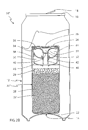
Fig. 2a shows a partial intersected view of a further embodiment of a self-
cooling
container 1011 comprising all of the features of the self-cooling container
101 of Fig. 1
The self-cooling container 1011 of the present embodiment, however, further
comprises an auxiliary cup-shaped wall 46 mounted outside and below the main
CA 02746246 2011-06-08
WO 2010/066772 PCT/EP2009/066697
cup-shaped wall 38. An auxiliary gripping flange 48 constituting an elongation
of the
main gripping flange 42 together with an auxiliary cup-shaped wall 46 and a
main
cup-shaped wall 38 defines an auxiliary reactant chamber 50. The auxiliary
reactant
chamber 50 is filled with an auxiliary reactant granulate, which constitutes
one of the
5 reactants of the reaction. The other reactant is located in the main
reactant chamber
28 , thereby eliminating the need of a coating of the reactant granulates.
Fig. 2b shows the self-cooling container 104 of Fig.. 2a when the beverage can
has
been opened and the chemical reaction has been activated. In the activated
state,
10 the circumferential gripping flange has detached from the cup-shaped wall
38 as
shown in Fig, 1 a, thereby allowing the water in the water chamber 44 to flow
into the
main reactant chamber 28. At the same time, the auxiliary gripping flange 48,
which
is connected to the flexible diaphragm 30 via the circumferential gripping
flange 42
will detach from the auxiliary cup-shaped wall 46 and allow the auxiliary
reactant to
15 enter the main reactant chamber 28, thereby activating the chemical
reaction. The
present embodiment requires an additional chamber but has the benefit of not
requiring any coating of the reactant granulates, since the reactants are
stored in
separate chambers.
20 Fig. 3a shows a self-cooling container 10111 similar to the self-cooling
container 101,
shown in Fig, 2.. The self-cooling container 10111 has a pressure space 32,
however,
instead of a gas permeable membrane, a water-soluble plug 27 is accommodated
in
the top 24 of the cooling device 20, The water-soluble plug 27 may be of any
water-
soluble material, which is non-toxic and may form a pressure proof plug of
sufficient
25 rigidity, which dissolves within a few minutes when subjected to an aqueous
solution
such as beverage. It is contemplated that non-toxic implies that the material
being
allowed for usage in consumables by e.g.. a national health authority or the
like.
Such materials may include sugar, starch or gelatine. The soluble plug 27
allows the
cooling device 20 to be prepared and pressurised an extended time period such
as
30 days or weeks before being used in a beverage can. The soluble plug 27
prevents
the pressure inside the cooling device 20 i.e. inside the main reactant
chamber 28,
the water chamber 44 and the pressure space 32 to escape to the outside
through
the top 24. The flexible membrane is in the present embodiment made of rubber
and
CA 02746246 2011-06-08
WO 2010/066772 PCT/EP2009/066697
31
comprises a support diaphragm 31 as well made of rubber and which is located
juxtaposed to the cup-shaped wall 38 and extending between the circular wall
40
and the rounded circumferential reinforcement bead 34 . To equalize the
pressure
between the flexible diaphragm 30 and the support diaphragm 31 a pressure
inlet
52 is located on the flexible membrane to allow the pressure to equalise
between
the pressure space 32 and the space between the support diaphragm 31 and the
flexible membrane 30.
Fig. 3b shows a self-cooling container 10111 comprising a beverage can 12 and
a
cooling device 20 located inside the beverage can 12 before the chemical
reaction
has been activated.. The soluble plug 26' will prevent the pressure inside the
pressure 32 to escape to the outside of the cooling device 20, while the
beverage
can 12 is filled with beverage and carbonated/pressurised. After a certain
time
period or alternatively during pasteurisation, the soluble plug 26' is
dissolved and
fluid communication is allowed between the interior of the beverage can 12 and
the
pressure space 32 of the cooling device 20. The pressure inside the beverage
can
12 keeps the cooling device 20111 in its pre-activated state, i.e., the
chemical reaction
is not started.,
Fig. 3c shows a self-cooling container .10111 according to Fig.. 3b when the
beverage
can 12 has been opened and the chemical reaction has been activated. When the
beverage can 12 has been opened, the pressure inside the beverage can 12 as
well
as inside the pressure space 32, falls to the ambient pressure outside the
beverage
can 12. This causes the chemical reaction in the cooling device 20 to activate
as
previously described in connection with Fig. 2.
Fig, 4a shows a further embodiment of a self-cooling container 10ly. The self-
cooling
container 101v comprises a beverage can 12' similar to the beverage can
described
in connection with Fig. 1 to 3.. The beverage can 12' has a beverage can base
14', a
lid 16' and a cooling device 20', which is fixated onto the lid 16' and
extending into
the beverage can 12'.. The cooling device 201" comprises a cylindrical
aluminium
tube extending towards a beverage can base 14. A pressure inlet 52 is defined
in
the lid 16' for allowing fluid communication between the outside atmospheric
CA 02746246 2011-06-08
WO 2010/066772 PCT/EP2009/066697
32
pressure and a pressure space 32, which is defined inside the cooling device
between the lid 16' and a diaphragm 30'.. The diaphragm 30' is made of a
flexible
material such as rubber and forms a fluid tight barrier between the pressure
space
32' and a water chamber 44'. The water chamber 44 is separated from a main
reactant chamber 28' by a rupturable diaphragm 54. The rupturable diaphragm 54
is
made of a flexible material similar to the diaphragm 30' The rupturable
diaphragm
54 may be ruptured, i.e. irreversibly opened by a piercing element 56
constituting a
needle, which is located inside the main reactant chamber 28' and pointing
towards
the rupturable diaphragm 54. The main reactant chamber 28' is filled with a
coated
10. granulate reactant similar to the embodiments described in connection with
Fig. 1 to
3. The main reactant chamber 28' is separated from the beverage can 12' by a
bottom 22' which is located near, however not contacting, the beverage can
base
14'. The bottom 22' is made of the same material as the outer wall of the
cooling
device 20, i.e. preferably aluminium. The bottom 22' is connected to the outer
wall of
the cooling device 20ly via a corrugation 58 allowing the bottom 22' to be
flexible
and bistable, i.e. able to define a mechanical stable inwards and outwards
bulging
state, respectively. When the beverage can 12' is filled and pressurised, the
pressure inside the beverage can 12' will cause the bottom 22', the rupturable
diaphragm 54' and the diaphragm 30' to bulge in an inwards direction.
Fig. 4b shows the self-cooling container 101v comprising a beverage can 12',
which
has been opened by operating the tab 18. By operating the tab 18, an embossing
in
the lid 16 is ruptured and an opening is formed in the lid 16 allowing the
beverage to
be poured out and the pressure to escape. When the pressure escapes, the
bottom
22' of the cooling device 201v will bulge towards the beverage can base 14 due
to
the internal pressure in the cooling device 201v, The bottom 22' is made
bistable, so
that when bulging towards the beverage can base 14, a subatmosphere pressure
is
resulting in the main reactant chamber 28' causing the rupturable diaphragm 54
and
the diaphragm 30 to bulge towards the beverage can base 14. The rupturable
diaphragm 54 will therefore bulge into the piercing element 56 causing the
rupturable diaphragm 54 to burst.. The rupturable diaphragm 54 may be a
bursting
diaphragm or alternatively have a predetermined breaking point or
alternatively have
a built-in tension so that when the piercing element 56 enters the rupturable
CA 02746246 2011-06-08
WO 2010/066772 PCT/EP2009/066697
33
diaphragm 54, an opening is created between the water chamber 44' and the main
reactant chamber 28' causing the water in the water chamber 44' to enter the
main
reactant chamber 28', thereby activating the chemical reaction resulting in a
cooling
of the beverage. The chemical reaction will draw energy from the surrounding
verge
and thereby cause a relative cooling of at least 10 degrees C , preferably 20
degrees CO or more.
Fig.. 5a shows a self-cooling container 10v, similar to the self-cooling
container 101v
of Fig. 4. Instead of a rupturable diaphragm, the self-cooling container 10v
has a
main cap 60 made of plastic material separating the water chamber 44 and the
main
reactant chamber 28' The main cap 60 is held in place by a main cap seat 62
constituting an inwardly protruding flange which is fixed to the inner wall of
the
cooling device 20v and which is applying a light pressure onto the main cap
60.. The
main cap 60 constitutes a shallow circular plastic element forming a fluid
tight
connection between the water chamber 44' and the main reactant chamber 28'.
Fig.. 5b shows the self-cooling container 10v according to Fig. 5a, which has
been
opened and activated similar to the beverage can described in Fig. 4b. When
the
beverage can 12' has been opened, the bottom 22' of the cooling device 20v
will
bulge towards the beverage can base 14, which will cause a pressure drop
inside
the main reactant chamber 28' resulting in the main cap 60 being ejected from
the
main cap seat 62 and falling into the main reactant chamber 28, thereby
allowing
fluid communication between the water chamber 44' and the main reactant
chamber
28'. Water will therefore flow from the water chamber 44 into the main
reactant
chamber 28', thereby activating the chemical reaction and causing the beverage
to
be cooled. As the granulate reactant is being dissolved, the main cap 60 may
fall
towards the bottom 22 of the cooling device 20v.
Fig. 6a shows a self-cooling container 10vf similar to the self-cooling
container 10v
shown in Fig. 5, however, instead of a main cap seat and a main cap, the
present
embodiment comprises a support mesh 66 and a rupturable diaphragm 54
separating the water chamber 44' and the main reactant chamber 28'. The
support
mesh constitutes a grid made of metal or plastics, which is placed in a
juxtaposed
CA 02746246 2011-06-08
WO 2010/066772 PCT/EP2009/066697
34
position in relation to a rupturable diaphragm 54, where the diaphragm is
facing the
main reactant chamber 28 and the rupturable diaphragm 54 is facing the water
chamber 44. The rupturable diaphragm 54 constitutes a burst membrane, which
prevents fluid communication between the water chamber 44' and the main
reactant
chamber 28'. The support mesh 56 prevents the rupturable diaphragm 54' from
bulging upwardly towards the pressure inlet 52 and rupture in case the
pressure in
the main reactant chamber exceeding the pressure in the water chamber 44.
Fig. 6b shows a self-cooling container 10vi when the beverage can 12' has been
opened, By opening the beverage can, the pressure is reduced inside the
beverage
can 12' causing the bottom 22' to bulge towards the beverage can base 14,
thereby
reducing the pressure inside the main reactant chamber 28'., The reduced
pressure
inside the main reactant chamber 28 causes the rupturable diaphragm 54' to
bulge
towards the beverage can base -14'. The rupturable diaphragm 54' is a burst
membrane, which is caused to rupture without use of a piercing element. The
rupturable diaphragm 54' may constitute a non resilient which is caused to
burst by
the pressure difference between the main reactant chamber 28 and the water
chamber 44', thereby establishing a fluid communication between the water
chamber 54' and the main reactant chamber 28, The water entering the main
reactant chamber 28' from the water chamber 44' will activate the chemical
reaction
causing a cooling effect on the surrounding beverage as described previously
in the
figures 4 to 5.
Fig. 7a shows a self-cooling container 10v similar to the self-cooling
container 10'
of fig. 6, however, instead of a rupturable diaphragm and a piercing element,
a
telescoping valve 68 is separating the water chamber 44' and the main reactant
chamber 28'. The telescoping valve 68 constitutes a plurality of valve
elements 69
70 71. The valve elements constitute circular cylindrical flange elements. The
first
valve element 69 having the largest diameter is fixated to the inner wall of
the
cooling device 20v". The first valve element 69 is protruding slightly towards
the
bottom 22' of the cooling device 20'' and constitutes an inwardly protruding
bead.
The second valve element 70 constitutes a flange element having an upper
outwardly protruding bead sealing against the first valve element and an
inwardly
CA 02746246 2011-06-08
WO 2010/066772 PCT/EP2009/066697
protruding bead sealing against the outwardly protruding bead of the first
valve
element 69. The third valve element 71 constitutes a cup-shaped element having
an
upper outwardly protruding bead sealing against the outwardly protruding bead
of
the second valve element 70 and a lower horizontal surface sealing against the
5 lower inwardly protruding bead of the second valve element 70.
Fig.. 7b shows the self-cooling container 10v11 of Fig. 7a when the beverage
can 12'
has been openedõ As previously described in Fig. 6b, the opening of the
beverage
can 12' causes the bottom 22 of the cooling device 20' to bulge outwardly,
thereby
10 causing the pressure in the main reactant chamber 28' to be reduced,
thereby
causing the second and third valve elements 70 71 to move in a direction
towards
the bottom 22 of the cooling device 20vn so that the outwardly protruding bead
of the
second valve element 70 seals against the inwardly protruding bead of the
first
valve element 71 and the outwardly protruding bead of the third valve element
71
15 seals against the inwardly protruding bead of the second valve element 70,
The
second and third valve elements 70 71 are provided with circumferentially
distributed valve apertures 72, which allow fluid communication between the
water
chamber 44' and the main reactant chamber 28'. Thus, water is allowed to flow
from
the water chamber 44 to the main reactant chamber 28..
Fig. 8a shows a self-cooling container 10v"' comprising similar to the self-
cooling
container 101v described in connection with Fig. 4, however, an auxiliary
reactant
chamber 50' is provided between the water chamber 44' and the main reactant
chamber 28'. The water chamber 44' is separated from the auxiliary reactant
chamber 50 by a support 74 and a rupturable diaphragm 54". The support 74
seals
between the inner wall of the cooling device 20' and the rupturable diaphragm
54,
which is centrally located and covering a descending pipe 76, which is
protruding
towards the main reactant chamber 28'.. The auxiliary reactant chamber 50' and
the
main reactant chamber 28' are separated by a water soluble diaphragm 78..
Fig.. 8b shows the self-cooling container 10v "' as described in Fig. 8a when
the
beverage can 12' has been opened.. The opening of the beverage can causes the
bottom 22 of the cooling device 20' to bulge outwardly as described above in
CA 02746246 2011-06-08
WO 2010/066772 PCT/EP2009/066697
36
connection with Fig. 4 to Fig. T. The reduced pressure in the main reactant
chamber
28' causes the water soluble diaphragm 78 to bulge towards the bottom 22' and
the
resulting low pressure in the auxiliary reactant chamber 50' causes the
rupturable
diaphragm 54" to burst and allowing the water in the water chamber 44' to
enter the
descending pipe 76 and flow towards the water soluble diaphragm 78.. When the
water soluble diaphragm is dissolved by the water from the descending pipe,
the
auxiliary reactants, constituting the first of the two reactants required for
the
chemical reaction to activate and stored in the auxiliary reactant chamber 50,
will be
allowed to react with the main reactant, constituting the second of the two
reactants
required for the chemical reaction to activate and stored in the main reactant
chamber 28'.. The resulting activation of the chemical reaction is caused by
the
mutual contacting of the reactants, The reaction yields the cooling effect,.
Fig. 9a shows a self-cooling container 1 O'x similar to the self-cooling
container 101v
of Fig.. 4, however comprising a cooling device 20`x being made completely of
polymeric material. The cooling device 20" constitutes a polymeric cylinder
having
three parts, the first part being a rigid cylinder part 80 which is fixated to
the lid 16 of
the beverage can 12'. The lid is gas tight, thus not providing any fluid
communication between the outside and the upper rigid cylinder part 80. The
upper
rigid cylinder part 80 protrudes into the beverage can 12' and is connected to
the
second cylinder part constituting an intermediate flexible cylinder 82, which
is in turn
connected to the third cylinder part constituting a lower rigid cylinder part
81, which
is sealed off close to the beverage can base 14.. The upper rigid cylinder
part 80
constitutes a water chamber and a lower rigid cylinder part is filled with a
reactant
granulate. When the beverage can 12' is filled and pressurised, the pressure
will
cause the intermediate flexible cylinder to be squeezed off, forming a squeeze
off
valve, due to the lower pressure inside the cooling device 20x compared to the
pressure in the beverage can 12.
Fig. 9b shows the self-cooling container 10'x of Fig. 9a when the beverage can
12'
has been opened. The lower pressure in the beverage can 12' will cause the
intermediate flexible cylinder 82 to assume a non-squeezed state allowing
fluid
communication between the upper rigid cylinder part 80 and the lower rigid
cylinder
CA 02746246 2011-06-08
WO 2010/066772 PCT/EP2009/066697
37
part 81 .This way the intermediate cylinder 82 forms a channel so that the
water
contained in the upper rigid cylinder part will flow into the lower rigid
cylinder part,
thereby activating the coated granulate reactant stored in the lower rigid
cylinder
part 81..
Fig,. 9c shows the self-cooling container 10'x comprising a beverage can 12'
having
a cooling device 2dX similar to Fig. 9a and Fig. 9b, however, additionally
providing
an optional circumferential gripping member 83 located on the inner wall on
the
intermediate flexible cylinder 82. The gripping member 83 is accommodating a
separation element 84 constituting a small disc shaped element of plastic
material,
which provides a more secure sealing between the water stored in the upper
rigid
cylinder part 80 and the reactant granulate stored in the lower rigid cylinder
part 81.
The gripping member 83 and the separation element 84 are preferably made of
substantially rigid plastics. The gripping member 83 comprises gripping
elements
which may interlock with corresponding beads on the separation element 83.
Fig, 9d shows a close-up of the gripping member 83 and the separation element
84
of Fig. 9c when the beverage can 12' is an unopened and pressurised state.
Fig. 9e shows a close-up view of Fig. 9d, when the beverage can 12' has been
opened and the reduced pressure from the outside of the intermediate flexible
cylinder 82 causes the walls of the intermediate flexible cylinder 82 to
separate and
causes the separation element to detach from the gripping member 83, thus
allowing fluid communication between the upper rigid cylinder part 80 and the
lower
rigid cylinder part 81. By using the gripping member 83 and the separation
element
84, a well defined separation is accomplished between the upper rigid cylinder
part
80 and the lower rigid cylinder part 81 when the cooling device 20" is
activated and
the walls of the intermediate flexible cylinder 82 are separated.
Fig. 10a shows a cooling device 10x similar to the cooling device 10v of Fig..
5.. The
cooling device 20X has an auxiliary reactant chamber 50', which is located
between
the water chamber 44' and the main reactant chamber 28'. The auxiliary
reactant
chamber 50' is separated from the main reactant chamber 28' by a main cap 60'
and
CA 02746246 2011-06-08
WO 2010/066772 PCT/EP2009/066697
38
a main cap seat 62'. The auxiliary reactant chamber is separated from the
water
chamber 44' by an auxiliary cap 86 and an auxiliary cap seat 88,. The main cap
seat
62 and the main cap 60 as well as the auxiliary cap seat 88 and the auxiliary
cap 86
work in the same way as the main cap seat and the main cap described in
connection with Fig, 5..
Fig. 10b shows the self-cooling container 10x of Fig, 10a when the beverage
can 12
has been opened and the bottom 22' of the cooling device 20x has been caused
to
bulge outwardly due to the reduced pressure inside the beverage can 12', This
causes the auxiliary cap 62 and the main cap 60' to fall downwardly in
direction
towards the bottom 22' due to the pressure force, which causes the water, the
auxiliary reactant and the main reactant to mix and thereby activate the
chemical
reaction.
Fig. 11 a shows a self cooling container 10x' similar to the self-cooling
container 10x
described in connection with Fig, 10, however, instead of an auxiliary cap
seat and
an auxiliary cap, a support mesh 66 and the rupturable diaphragm 54' is
provided.
The support mesh 66 and the rupturable diaphragm 54' works in the same as in
the
previously described self-cooling container 10v' of Fig. 6.
Fig., 11 b shows the self-cooling container 1 Ox' of Fig. 11 a when the
beverage can
12' has been opened and the cooling device 20x' has been activated.
Fig.. 12a and Fig. 12b show a self-cooling container l Ox" similar to the self-
cooling
container 10x, where the rupturable diaphragm 54 and the piercing element 56
of
Fig.. 4 have been combined with the support mesh 66 and the rupturable
diaphragm
54' of Fig. 6..
Fig. 13a shows a self-cooling container 10x' comprising a beverage can 12"
having
a submerged cooling device 20x" constituting a cooling widget. The cooling
device
20x" defines a cylinder of preferably polymeric material, which may move
freely in
the beverage inside the beverage can 12". The cooling device 20" comprises a
pressure space 32", a water chamber 44" and a main reactant chamber 28". The
CA 02746246 2011-06-08
WO 2010/066772 PCT/EP2009/066697
39
pressure space 32" comprises a pressure inlet 52' for allowing a small amount
of
beverage to enter the cooling device 20". The pressure space 32' and the water
chamber 44" are separated by a flexible diaphragm 40". The water chamber 44"
and the main reactant chamber 28' are separated by a plug seat 90 and a main
plug
89 centrally located in the plug seat 90. The plug seat 90 seals between the
main
plug 89 and the inner wall of the cooling device 20 The main plug 89 is
connected
to the diaphragm 30". The overpressure in the beverage can 12' keeps the
diaphragm 30" in relaxed and non-activated state. The main plug 89 separates
the
water in the water chamber 44" and granulates reactants in the main reactant
chamber 28
Fig. 13b shows the self-cooling container 10xni as described in Fig. 13a when
the
beverage can 12" has been opened. When the beverage can 12" has been opened,
the pressure inside the beverage can 12" and pressure space 32" is reduced and
the pressure in the water chamber 44" causes the diaphragm 30" to bulge
towards
the pressure inlet 52 When the diaphragm 30" bulges towards the pressure inlet
52', the main plug 89, which is connected to the diaphragm 30" will disconnect
from
the plug seat 90 and fluid communication is accomplished between the water
chamber 44" and the main reactant chamber 28", allowing water to enter the
main
reactant chamber 44 and activating the chemical reaction which is causing the
beverage to be cooled.
Fig. 14a shows a self-cooling container 10xiv similar to the self-cooling
container
10x61 shown in Fig. 13, however where the cooling device 20xiv additionally
comprising an auxiliary reactant chamber 50" including a reaction control
fluid for
reducing the reaction time, The auxiliary reactant chamber 50" is located
between
the water chamber 44" and the main reactant chamber 28". The water chamber 44"
and the auxiliary reactant chamber 50" are supported by a main plug seat 90
and a
main plug 89 and the auxiliary reactant chamber 50" and the main reactant
chamber
28" are supported by an auxiliary plug seat 94 and an auxiliary plug 92. The
auxiliary plug 92 is connected to the main plug 89,
CA 02746246 2011-06-08
WO 2010/066772 PCT/EP2009/066697
Fig. 14b shows the self-cooling container 10x1v of Fig.. 14a when the beverage
can
12" has been opened.. The pressure loss when opening the beverage can 12" will
cause the diaphragm 30 to bulge towards the pressure inlet 22'. Since both the
main
plug 89 and the auxiliary plug 92 are connected to the diaphragm 30", both the
5 water chamber 44" and the auxiliary reactant chamber 50" will establish
fluid
communication with the main reactant chamber 28". This causes the water in the
water chamber 44' and the reaction control fluid in the auxiliary reactant
chamber
50" to flow into the main reactant chamber 28", which is filled with the
coated
granulate reactant. When both the reactants are mixed together in water, the
10 chemical reaction is activated and the cooling is initiated. The reaction
control fluid
prolongs the cooling effect and may be used for e.g. preventing ice formation
inside
the beverage can 12.
Fig. 15a and 15b shows a self-cooling container 10xv similar to the self-
cooling
15 container 10xiv shown in Fig. 14, however, instead of using a flow control
fluid, the
second reactant is stored in the auxiliary reactant chamber 50", thereby
excluding
the use of a coating of the reactant, When activation is established by
opening the
beverage can 12" and the first granulate reactant in the main reactant chamber
28 is
mixed with the second granulate reactant in a water solution, the chemical
reactions
20 is activated.
Fig, 16a shows a self-cooling container 10xv constituting a cooling box
comprising
an insulating carrier 96 being made of rigid insulating material, such as
Styrofoam or
the like. The insulating carrier 96 has a cavity 97 defining a space suitable
for
25 accommodating six standard beverage cans 12"` i..e. typically sized
beverage cans
having a shape corresponding to the beverage cans described above and
designated the reference numeral 12, however exclusive of the cooling device.
The
inner cavity 97 defines a flat bottom surface and an inner continuous sidewall
which
has bulges 98 for defining a plurality of interconnected arcs corresponding to
the
30 outer surface of six beverage cans defining positions for individual
placement of the
beverage cans 12"' when placed in the well known 3x2 "sixpack" configuration
so
that a stable and secure positioning is achieved. The inner cavity 97 is thus
configured for accommodating six beverage cans 12"' in two rows with three
CA 02746246 2011-06-08
WO 2010/066772 PCT/EP2009/066697
41
beverage cans 12"' in each row. A spacer 99 is provided for filling up the
inner
space between the six beverage cans 12"' for added stability. The spacer 99 is
preferably made in a non-thermal insulating or weakly thermal insulating
material
such as plastics, metal or cardboard, In the self-cooling container 10xvl, one
of the
beverage cans 12"' has been substituted by a cooling device 20XV1 having an
external shape corresponding to a beverage can 12"'.. The cooling device 20xv'
has
an activation button 100, which is pressed for activating the chemical
reaction inside
the cooling device 20xvl. The inside of the cooling device 20XV1 may
correspond to
any of the previous cooling devices shown in fig 1-15, except that the
activation is
performed by a mechanical action from the outside, i.e. by pressing the button
100..
The button may be directly coupled to e.g, a rupturable diaphragm or the like
separating the two reactant, thus by pressing the button the diaphragm is
ruptured
allowing the two reactants to contact each other. Alternatively the button 100
may
be acting on a pressure space, and the change of pressure causes a flexible
diaphragm to move and start the chemical reaction.
Fig. 16b shows a top view of the self-cooling container 10'x'' comprising the
insulating carrier 96 accommodating the five beverage cans 12 and the cooling
device 20xvl. The self-cooling container 10xv' may be stored in room
temperature.
When the beverage in the beverage cans is about to be consumed, the activation
button 100 on the cooling device 20xv1 is pressed and the cooling is
activated. An
optional cover on the insulation carrier 96 may be provided as an additional
insulation.
Fig, 17a shows a self-cooling container 10xv" constituting an alternative
configuration of the self-cooling container 10"'. The cooling device 20x'"
corresponding to the cooling device 20x'' of fig 16, is accommodated in a
centrally
located spacer 99' and 6 beverage containers are accommodated in an insulation
carrier 96' surrounding the spacer 99. The insulation carrier 96' has a
rounded outer
shape and an inner cavity 97' having bulges 98' for accommodating the six
beverage cans 12"' in a circumferential configuration around the centrally
located
spacer 99.
CA 02746246 2011-06-08
WO 2010/066772 PCT/EP2009/066697
42
Fig. 17b and c shows a perspective view and a top view, respectively, of the
self-
cooling container 10xvl.
Fig. 18a-f show the steps of filling and pressurising a beverage can 12 of the
type
shown in the Figures 1 to 3, including a cooling device 20 of the type shown
in fig 1-
3,
Fig. 18a shows the process of ventilating the beverage can 12 prior to
filling. The
beverage can 12 includes a cooling device 20 and a lid flange 104. The
beverage
can is typically ventilated three times by inserting a ventilating hose 102
and
injecting carbon dioxide (C02) into the beverage can 12. The carbon dioxide
will
substitute the air inside the beverage can 12. Any amount of residual air
inside the
beverage can 12 may result in deterioration of the beverage. Subsequent to the
ventilation, the beverage can 12 is filled with beverage as shown in fig 20b.
Fig. 18b shows the beverage filling process, in which a filling hose 103 is
inserted
and beverage is injected into the beverage can 12. The beverage is pre-
carbonated
and having a low temperature of just a few degrees centigrade above the
freezing
point for accommodating a maximum amount of carbon dioxide dissolved in the
beverage.
Fig.. 18c shows the filled beverage can 12 when the filling hose 103 has been
removed. The beverage is kept in a carbon dioxide atmosphere having a
temperature just above the freezing point to be able to be saturated with
carbon
dioxide without the need of a high pressurized environment.
Fig. 18d shows a beverage can 12, where a lid 16 has been sealed on to the lid
flange 104. The lid 16 is folded on to the lid flange 104 forming a pressure
tight
sealing.
Fig. 18e shows the beverage can 12 inside a pasteurisation plant 106. The
pasteurisation plant comprises a water bath of about 70 degrees centigrade.
The
pasteurisation process is well known for retarding any microbiological growth
in food
CA 02746246 2011-06-08
WO 2010/066772 PCT/EP2009/066697
43
products.. During pasteurisation, the pressure inside the beverage can will
rise to
about 6 bar due to the heating of the beverage and the resulting release of
carbon
dioxide from the beverage. The cooling device should be made sufficiently
rigid to
be able to withstand such high pressures. In addition, the reactants used
inside the
cooling device should remain unaffected of the increased temperature and
pressure,
i.e. they should not combust, react, melt, boil or otherwise change their
state making
a later initiation of the reaction impossible or ineffective. It should also
be noted that
for non-pasteurised beverages, such as mineral water, the reactants should
still
remain unaffected up to a temperature of at least 30 to 35 degrees centigrade,
which is a temperature which may be achieved during indoor or outdoor storage.
Fig. 18f shows the beverage can 12 in room temperature. The pressure inside
the
beverage can 12 is about 3 to 5 bar, which is sufficient for preventing
activation of
the cooling device 20.. When the beverage can is being opened, the pressure
inside
will escape to the surrounding atmosphere, the beverage can 12 will assume
atmospheric pressure of 1 bar and the cooling device 20 will activate as
previously
discussed in connection with fig 1-15,.
Fig. 19a-e show the steps of filling and pressurising a beverage can 12 of the
type
shown in the Figures 13 to 15, including a cooling device of the type shown in
figures 13 to 15, The process is similar to the filling process described
above in
connection with fig 18, except for the positioning of the cooling device 20 in
fig 21c,
which occurs after filling but before applying the lid 16.
Fig. 20a to 20f show the steps of filling and pressurising a beverage can 12
of the
type shown in the Figures 4 to 12, including a cooling device of the type
shown in fig
4 to 12. As the cooling device 20 is attached to the lid 16, the cooling
device and the
lid is attached to the beverage can 12 in one piece in fig 20d.
Fig. 21 a shows a party keg system 110 having a built-in pressurisation system
and
a self-cooling beverage container. The party keg constitutes a simple beverage
dispensing system for typically single use and accommodating about three to
ten
litres of beverage and typically five litres of beverage. Party kegs are often
used for
CA 02746246 2011-06-08
WO 2010/066772 PCT/EP2009/066697
44
minor social events such as private parties and the like. Party kegs often
include a
pressurisation and carbonisation system and one such party keg system has been
described in the pending and not yet published European patent application
No..
08388041.9.. The party keg mentioned in 08388041.9, however, does not provide
any internal cooling, thus requiring external cooling until the beverage is
about to be
consumed.. The party keg 110 comprises a housing 112, which preferably is made
of a light insulating material, such as styrofoam or the like. The housing
comprises
an upper space 114 and a lower space 116, which are separated by a closure
118..
A beverage keg 120 including a suitable amount of beverage is accommodated in
the lower space 116 and fixated to the closure 118,. The beverage keg 120 has
an
upwards oriented opening 122, which is fixated to the closure 118 by a
fixation
flange 123. A tapping line 124 is extending through the opening 122 into the
beverage keg 120. The tapping line constitutes an ascending pipe and extends
through the closure 118 via the upper space 114 to the outside of the housing
112.
Outside the housing 112, a tapping valve 126 is used for controlling the flow
of
beverage through the tapping valve 126. When the tapping valve 126 is in open
position, beverage will flow through the tapping line 124 and leave the party
keg
system 110 via a beverage tap 127, while the beverage may be collected in a
glass
or the like. A gasket 128 seals the tapping line 124 to the closure 118, A
pressure
generator 130 is located in the upper space 114. The pressure generator may be
a
cartridge of pressurised carbon dioxide or alternatively, a chemical pressure
generator. The pressure generator 130 is connected to the beverage keg 120 by
a
pressurising hose 132. The pressurising hose 132 is connected to the interior
of the
beverage keg 120 via the opening 122 and is sealed to the closure 118 by the
gasket 128. A pressurisation knob extending between the pressure generator 130
and the outside of the housing 112 is used for initiating the pressurisation
of the
beverage keg 120. The beverage keg 120 is filled with beverage and
additionally
accommodates a cooling device 20xxÃ. The cooling device includes a main
reactant
chamber 28 and an auxiliary reactant chamber 50, which are separated by a
water-
soluble diaphragm 78.. A fluid inlet 136 is located next to the water-soluble
diaphragm. The fluid inlet 136 will allow pressurised fluid to enter the
cooling device
20xxi The fluid inlet 136 comprise a check valve 138, preventing any reactant
from
CA 02746246 2011-06-08
WO 2010/066772 PCT/EP2009/066697
flowing out of the fluid inlet 136 and contact the beverage due to pressure
variations
in the beverage keg 120,.
Fig. 21 b shows the party keg system 110 on Fig. 23a when it has been
activated by
5 operating the pressurisation knob 134. When the pressurisation knob 134 has
been
operated, pressurised carbon dioxide will enter the beverage keg 120 and
pressurise the beverage accommodated inside. Beverage will thus enter the
fluid
inlet 136 of the cooling device 20 ' and dissolve the water-soluble diaphragm
78.
This causes the main reactant located in the main reactant chamber 28 to mix
with
10 the auxiliary reactant located in the auxiliary reactant chamber 50 and
thereby
activate the cooling reaction. The functional principle of the cooling device
20 is
similar to the functional principle of the cooling device 20v"' of Fig. 8,
however, in an
opposite direction, i.e., whereas the cooling device 20v"' of Fig. 8 is
initiated by a
reduction of pressure, the cooling device 20xxi of Fig. 21 is activated by an
increase
15 in pressure. This way, the party keg system 110 must not be pre-cooled and
may be
stored in room temperature. When the beverage is about to be consumed, the
operator presses the pressurisation knob, which automatically initiates the
cooling
reaction and after a few minutes, a cool beverage may be dispensed by
operating
the tapping valve 126. It is further contemplated that the housing of the
party keg
20 system may be omitted or replaced by a simpler housing if for instance no
insulation
is needed.
Fig. 22a shows a beverage dispensing system 140 for private or professional
use.
Such beverage dispensing systems are well known in the art and have been
25 previously described in the international PCT application 2007/019853. The
beverage dispensing system 140 comprises a pivotable enclosure 142, which is
attached to a base plate 144. The interior of the enclosure 142 defines a
pressure
chamber 146. The pressure chamber 146 is separated from the base plate 144 by
a
pressure lid 148. The pressure lid 148 is sealed in relation to the base plate
144 by
30 sealings 150. The side of the pressure lid 148 facing inwardly towards the
pressure
chamber 146 constitutes a coupling flange 152.. The coupling flange 152 is
used for
fixating a beverage keg 120', which is accommodated within and fills the
greater part
of the pressure chamber 146. The beverage keg 120' constitutes a collapsible
keg
CA 02746246 2011-06-08
WO 2010/066772 PCT/EP2009/066697
46
which is allowed to collapse due to the pressure force while the beverage is
dispensed. A cooling and pressurisation generator 156 is connected to the
pressure
chamber 146 for providing cooling and pressurisation for the beverage located
inside the beverage keg 146. A tapping line 124' connects the pressure chamber
146 to a tapping valve 126. The end of the tapping line 124 facing the
pressure
chamber 146 is provided with a cannula 151 for piercing through the coupling
flange
152 for allowing fluid communication between the interior of the beverage keg
120'
and the tapping valve 126. A tapping handle 154 is used for operating the
tapping
valve 126 between the shut-off position and the beverage dispensing position.
In the
beverage dispensing position, the handle 154 is moved from its normal vertical
orientation to a horizontal orientation, and beverage is allowed to flow
through the
tapping valve 126 and leave the beverage dispensing system 140 through a
beverage tap 127'. The interior of the beverage keg 120' accommodates beverage
and a cooling device 20xxn. The cooling device 20xx" which is held by a fixing
rod
158, comprises a main reactant chamber 28 and an auxiliary reactant chamber
50..
The main reactant chamber 28 and the auxiliary reactant chamber 50 are
separated
by a rupturable diaphragm 54,. The top of the cooling device 20xx1 is provided
with a
flexible diaphragm 30 to which a piercing element 56 is connected,. The
piercing
element 56 extends towards the rupturable diaphragm 54,
Fig. 22b shows the beverage dispensing system 140 of Fig. 24a and the pressure
chamber 146 has been pressurised. The pressure in the pressure chamber 146
acts
to deform the beverage keg 120 and causes the flexible diaphragm 30 to bulge
inwards towards the rupturable diaphragm 54. The rupturable diaphragm 54 will
thereby burst by the protruding piercing element 56 and the chemical reaction
for
providing cooling is activated. This way, a rapid cooling of the beverage
inside the
beverage keg 120' is accomplished and a cold beverage may be dispensed from
the
beverage keg 126' by operating the tapping handle 154 within a few minutes
from
activation. This way, the beverage keg must not be cooled and the long waiting
period for allowing the beverage to cool in a conventional way is avoided,.
The
cooling device 20xx" will rapid-cool the beverage when the beverage keg has
been
installed
CA 02746246 2011-06-08
WO 2010/066772 PCT/EP2009/066697
47
Fig.. 23a shows a beverage dispensing system 140' similar to the beverage
dispensing system 140 shown in Fig. 24 except the cooling device 20x""', which
works similar to the cooling device of Fig. 21. The cooling device 20
comprises a
main reactant chamber 28 and an auxiliary reactant chamber 50, which are
separated by a water-soluble diaphragm 78. The water-soluble diaphragm 78 is
connected to the coupling flange 152 by an activation channel 160õ The
coupling
flange 152 comprises a dual sealing membrane 162, which seals the activation
channel 160 from the interior of the beverage keg 120' and the outside of the
coupling flange 152. Fig. 23a shows the installation procedure of the beverage
keg
120' when the enclosure 142 is swung back for allowing access to the pressure
chamber 146..
Fig, 25b shows the beverage dispensing system 140 when the pressure lid 148
has
been attached to the enclosure 142 and the enclosure '142 has been swung back
to
the normal position sealing off the pressure chamber 146.. When the pressure
lid
148 is attached, the dual sealing membrane 162 is pierced and fluid is allowed
to
enter the activation channel 60 and tapping line 124'. When the pressure
chamber
146 is pressurised, beverage will enter the activation channel 160 and
dissolve the
water soluble membrane 78 at the end of the activation channel 160. Thus,
activation is accomplished and the chemical reaction will activate for
generating
cooling to the beverage as discussed in connection with Fig.. 22.
Fig. 24 shows a battle 164 having a bottle cap 166 with an integrated cooling
device
20xxvi. The bottle cap 166 has a cap flange 170 which is mounted on a
threading
168 near the mouth of the bottle 164. The cooling device 20xxv' is fixated to
the
bottle cap 166 and extending into the bottle 164. The cooling device 20xxv1
has an
activation button 96' for activating the cooling before the bottle cap 166 is
removed
from the bottle 164..
Fig. 25 shows a bottle 164 having a cooling device similar to the cooling
device
shown in Fig.. 26a except that a flexible diaphragm 30 is provided at the
bottom of
the cooling device 20. When the bottle cap 166 is twisted for allowing the
pressurised gas to escape from the bottle 164, the flexible diaphragm 30 will
bulge
CA 02746246 2011-06-08
WO 2010/066772 PCT/EP2009/066697
48
outwards and thereby initiate the chemical reaction similar to the self-
cooling
beverage container shown in connection with Fig. 4a.
Fig, 26a shows a bottle 164 having a bottle cap 166 and an outer cap 172. The
outer cap 172 is connected to a tooth rod, which is located within a cooling
device
20xxvi An intermediate diaphragm 174 separates the two reactants within the
cooling device 20.
Fig. 26b shows the bottle 164 of Fig, 27 when the outer cap 172 is twisted..
By
twisting the outer cap, the tooth rod 176 is rupturing the intermediate
diaphragm
174, thereby mixing the two reactants and activating the chemical reaction for
generating cooling,. After a few minutes, the outer cap 172 as well as the
bottle cap
166 may be removed and the chilled beverage may be accessed.
Fig. 27a shows a drink stick 180 constituting a cooling stick having an
integrated
cooling device 20, The drink stick 180 comprises a knob 182, which may be used
as
a handle and an elongated flexible reservoir 184 for accommodating the cooling
device. The cooling device 20 comprises a rupturable reservoir 186 comprising
a
first reactant, A second reactant is accommodated within an elongated flexible
reservoir 184 outside the rupturable reservoir 186.
Fig. 27b shows the activation of the drink stick 180 of Fig.. 28a, The drink
stick 180 is
activated by bending the drink stick 180 in the direction of the arrows. By
bending
the drink stick 180, the rupturable reservoir 186 is ruptured and the first
reactant is
mixed with a second reactant, thereby activating the chemical reaction
generating a
cooling effect.
Fig. 27c shows the drink stick 180 of Fig, 28b when the rupturable reservoir
has
been ruptured and the chemical reaction has been activated.
Fig, 27d shows the drink stick 180 of Fig. 28c when it has been inserted into
a bottle
164, The bottle 164 may be a conventional beverage bottle containing beer or
soft
drink having a room temperature. Due to the cooling effect of the drink stick
180, the
CA 02746246 2011-06-08
WO 2010/066772 PCT/EP2009/066697
49
beverage in the bottle 164 is cooled down to temperatures significantly lower
than
room temperature. It is further contemplated that the drink stick 180 may be
used
with other beverage containers for giving instant cooling to any beverage. For
example the drink stick 180 may be provided in a bar for use with a chilled
long
drink, such as gin and tonic, for allowing the drink to remain cooled for a
longer time
period,
In an alternative embodiment the above drink stick 180 may have a conical
shape
and being used together with an ice mould for instant manufacture of ice cubes
by
inserting the activated drink stick into the water filled ice mould.
Alternatively, the
drink stick may be have a cubic shape for direct usage as an ice cube in
drinks etc.
Fig, 28a shows a first embodiment of a bottle sleeve 188 which is suitable for
being
applied on the outside of a bottle 164 for use as e..g. a wine cooler. The
bottle
sleeve 188 comprises a main reactant chamber 28 and a water chamber 44, which
are separated by a rupturable diaphragm 54. The bottle sleeve 188 is fixated
to the
bottle by a fixation ring 189, which corresponds to a first groove 190 in the
bottle
sleeve 188. The fixation ring 189 is firmly attached to the bottle 164. The
first groove
190 is located juxtaposed the main reactant chamber 28. A second groove 191 is
located above the first groove 190 juxtaposed the water chamber 44.
Fig. 28b shows a bottle sleeve 188 when it has been activated by pushing it
downwards in direction of the arrows.. By pushing the bottle sleeve 188
downwards,
the fixation ring 189 will detach from the first groove 190 and be
accommodated in
the second groove 191.. Thereby, the rupturable diaphragm 54 will be ruptured
by
the fixation ring 189 and the water in the water chamber 44 will mix with the
reactant
in the main reactant chamber 28 and the cooling reaction is activated.
Fig. 28c shows a perspective view of a bottle 164 with an attached bottle
sleeve
190.
Fig. 29a shows a bottle sleeve constituting a wine cooler 192 in a flat
configuration,.
The wine cooler 192 comprises an outer layer 193, an inner layer 194 and a
CA 02746246 2011-06-08
WO 2010/066772 PCT/EP2009/066697
rupturable diaphragm 54 located between the outer layer and the inner layer,
The
space between the outer layer and the rupturable diaphragm constitutes a water
chamber 44 and the space between the rupturable diaphragm and the inner layer
194 constitutes a main reactant chamber 28,. The outer layer and the inner
layer 192
5 and 194 are flexible and constitute bistable layers having a first stable
positioning
the flat configuration shown in Fig. 29a.
Fig. 29b shows the wine cooler 192 in its second bistable position forming a
circular
sleeve shape, where the outer layer 193 is facing outwards and the inner layer
194
10 is facing inwards. The second stable position may be accomplished by
subjecting
the wine cooler 192 to a slight bending force. When the second configuration,
i.e.,
the circular configuration is assumed, the rupturable diaphragm 54 is being
ruptured
and thereby, the water and the reactant are being mixed for generating
cooling.
15 Fig.. 29c shows the wine cooler 192 in a perspective view.
Fig.. 29d shows the wine cooler 192 being attached to the outside of a
beverage
bottle 164. The beverage inside the beverage bottle 164 is thereby being
efficiently
cooled down to a drinking temperature,
It is contemplated that the efficiency of the above self-cooling beverage
containers
and cooling devices are strongly dependent on the heat transfer properties
(heat
transfer factor) of the cooling device. The heat transfer factor may be
modified by
changing the geometry, in particular the surface area in beverage contact, of
the
cooling device, e.g. by providing metal fins onto the cooling device, the heat
transfer
factor may be increased, thus the cooling efficiency is increased.
Consequently, by
encapsulating the cooling device in e.gõ Styrofoam or a hydrophobic material,
the
heat transfer factor may be reduced, i.e. the cooling efficiency is
decreased,.
Alternatively, a catalyser may be used for increasing the efficiency of the
chemical
cooling reaction, or an selective adsorption-controlling agent may be used for
reducing the efficiency of the chemical cooling reaction.
CA 02746246 2011-06-08
WO 2010/066772 PCT/EP2009/066697
51
It is further contemplated that the entire cooling device may be of flexible
material,
such as rubber or plastics, and itself constitute a flexible diaphragm,
A variant of the cooling device may be activated by pulling a string connected
to a
mixing member through the cooling device..
The cooling device shaped as a pipe within a pipe to cool a beverage flowing
through the inner pipe with reaction compartments in the space between the
inner
pipe and the outer pipe.
The cooling device shaped so as to be mountable around a tapping line for
cooling
beverage running through the tapping line..
The cooling device may have a breakable seal to avoid accidental activation.
The cooling device containing an arming device, the arming device comprising a
membrane permeable to the beverage, a saturated salt solution and a non-
permeable membrane separating the salt solution from the interior of the
cooling
device. Upon submersion of the cooling device in the container the water from
the
beverage enters through the permeable membrane by osmosis into the saturated
salt solution which increases in volume thus exerting pressure on the membrane
which is transmitted to the interior of the cooling device which results in
increased
interior pressure which can be used to activate the reaction as described
above.
Fig. 30 shows a simplified cubic crystal 195 as produced as an insoluble
product of
a non-reversible entropy increasing reaction according to the present
invention. The
crystal 195 has a with a total of 6 crystal faces, one of which is designated
the
reference numeral 196. Furthermore the crystal 195 defines a total of 8
corners one
of which is designated the reference numeral 198, On the faces of 196 of the
crystal
195 growths, one of which is designated the reference numeral 197 is present.
On the corners 198 growth of the crystal is inhibited by deposits, one of
which is
designated the reference numeral 199. The deposits are formed from a selective
adsorbent selectively adhering to the corners 198 of the crystal 195..
CA 02746246 2011-06-08
WO 2010/066772 PCT/EP2009/066697
52
The use of a selective adsorbent for preventing crystal growth is indicated in
reactions where a non-soluble product may encapsulate remaining reactants as
it is
formed thus halting the process.
In Fig. 31, a dispensing and refrigerator system according to present
invention is
shown designating the reference numeral 200 in its entirety. The system
comprises
a refrigerator cabinet 202 comprising a cabinet, in which an inner space is
defined
as illustrated in the lower right hand part of Fig. 31 illustrating a cut-away
part of the
refrigerator cabinet 202 disclosing a plurality of beverage cans, one of which
is
designated the reference numeral 204, which is supported on beverage can
sliding
chutes, one of which is designated the reference numeral 206 and which
supports a
total of eight beverage cans 204. Within the refrigerator cabinet 202, a
refrigerator
unit 208 and a heater unit 210 are enclosed serving the purpose of cooling and
heating, respectively, the inner chamber of the refrigerator cabinet 202 for
providing
a specific and preset thermostatically controlled temperature within the inner
chamber of the refrigerator cabinet 202, such as a temperature of 16 -20 C, in
particular a temperature approximately at or slightly above or slightly below
the
ambient temperature.
Provided the ambient temperature is substantially constant and above a certain
lower limit, the heater unit 210 may be omitted, as the inner chamber of the
refrigerator cabinet 202 is permanently cooled to a temperature slightly below
the
ambient temperature. As the inner temperature of the refrigerator cabinet 202
is set
at a specific thermostatically controlled temperature, each of the beverage
cans 204
may be contain a cooling device implemented in accordance with the teachings
of
the present invention for providing a cooling within a fairly short period of
time, such
as a period of time of a few minutes, e.g. 1-5 min., preferably approximately
2 min.
from the temperature at which the beverage cans are stored within the
refrigerator
cabinet 202 to a specific cooling temperature, such as a temperature of 5 C..
The refrigerator cabinet 202 shown in Fig. 31 is provided with a dispensing
aperture
212 to which a dispenser chute is connected, which dispenser chute is
designated
the reference numeral 216. The system 200 shown in Fig, 31 is advantageously
CA 02746246 2011-06-08
WO 2010/066772 PCT/EP2009/066697
53
provided with additional well-known elements or components, such as a coin
receptor or a card or chip reader for operating a dispensing mechanism
included
within the refrigerator cabinet 202 for controlling the dispensing of the
beverage
cans 204 from the system 200 one at a time after verification of payment or
verification of receipt of confirmation of transfer of a specific amount,
By the provision of a thermostatically controlled refrigerator cabinet 202, in
which
the individual beverage cans 204 are stored at a preset and constant
temperature,
preferably slightly below the ambient temperature, the overall consumption of
electrical energy from the main supply is dramatically reduced as compared to
a
conventional beverage can dispenser, in which the beverage cans are all cooled
to
the specific low temperature of use, i.e. a temperature of e,g. +5 C for
providing to
the user a beverage can of a convenient cooled beverage. By the reduction of
the
cooling to a temperature at or slightly below the ambient temperature, only a
fraction
of the electrical power consumption is to be used by the beverage dispensing
system according to the present invention as shown in Fig. 31 as compared to a
conventional beverage can refrigerator and dispenser system. Whereas a
convention beverage can dispenser and refrigerator system has to cool the
beverage cans to a temperature of 5 C from e.g. an ambient temperature of 25 C
or
even higher, the system 200 according to the present invention merely serves
to
cool the beverage cans to a temperature of e.g. 20 C reducing as a rough
calculation the energy consumption by at least 80% as compared to a
comparable,
conventional dispenser and refrigerator system cooling the beverage cans from
C to 5 C.
In Fig. 32, a refrigerator system according to present invention is shown
designated
the reference numeral 200' in its entirety. It is to be understood that the
beverage
dispenser system 200 shown in Fig. 31 may be modified into a conventional
fridge
or refrigerator having an openable front door 203' through which the
individual
beverage cans 204 may be supported on sets of shelves 206', on which the
beverage cans 204 are resting and from which the beverage cans 204 may be
caught by the users after opening the refrigerator front door 202'
CA 02746246 2011-06-08
WO 2010/066772 PCT/EP2009/066697
54
The refrigerator system 200' is similar to the refrigerator system 200 of fig
31 except
that the refrigerator system 200' comprises a refrigerator cabinet door 203'
which is
openable for exposing the interior of the refrigerator cabinet. A plurality of
beverage
bottles, one of which is designated the reference numeral 204', and kegs, one
of
which is designated 204", are supported on beverage can shelves, one of which
is
designated the reference numeral 206'.. The shelves 206' replace the shutes of
the
system described in connection with fig 31. Within the refrigerator cabinet
202', a
refrigerator unit 208 and a heater unit 210 are enclosed serving the purpose
of
cooling and heating, respectively, the inner chamber of the refrigerator
cabinet 202'
for providing a specific and preset thermostatically controlled temperature
within the
inner chamber of the refrigerator cabinet, such as a temperature of 16 -20 C,
in
particular a temperature approximately at or slightly above or slightly below
the
ambient temperature.
By cooling the individual beverage cans contained within the refrigerator
cabinet or
within a conventional fridge as described above to a specific and preset
temperature, the cooling device included in the individual beverage can and
implemented in accordance with the teachings of the present invention may be
designed to provide a preset and accurate cooling of the individual beverage
can
from the temperature within the refrigerator cabinet to the temperature at
which the
user is to drink or pour the beverage from the beverage can.
Although the invention has above been described with reference to a number of
specific and advantageous embodiments of beverage containers, beverage cans,
bottles, cooling devices, dispensing and cooling systems etc., it is to be
understood
that the present invention is by no means limited to the above disclosure of
the
above described advantageous embodiments, as the features of the above-
identified embodiments of the self-cooling container and also the features of
the
features of the above described embodiments of the cooling device may be
combined to provide additional embodiments of the self-cooling container and
the
cooling device, The additional embodiments are all construed to be part of the
present invention. Furthermore, the present invention is to be understood
encompassed by any equivalent or similar structure as described above and also
to
CA 02746246 2011-06-08
WO 2010/066772 PCT/EP2009/066697
be encompassed by the scope limited by the below points characterising the
present invention and further the below claims defining the protective scope
of the
present patent application.
5
CA 02746246 2011-06-08
WO 2010/066772 PCT/EP2009/066697
56
TABLE I
Reactant 1 Reactant 2 Reactant 3 Reactant 4 Measured cooling
per gram of coolant
(J/9)
Na2SO4, 1OH2O MgC12, 61120 92
Na2SO4, 101-120 CaC12, 61120 148
Na2SO4, 10H2O SrCl2, 61120 141
Na2SO4, 10H2O Mg(NO3)2, 61120 106
NazSO4r 10H2O Ca(NO3)2, 41120 172
Na2SO4, 10H2O LINO3 126
Na2SO4, 1OH2O LUNO3. 31120
Na2SO4, 10H2O Sr(NO3)551120 -
MgSO4i 71120 Ca(N03)2, 41120 49
MgSO4, 7H20 SrC12i 6H20 -
KAI(SO4)2, 12H20 CaC12, 6H20 88
NaAI(SO4)2, 12H20 CaC12, 6H20 -
NH4AI(SO4)2, 121120 Ca(N03)2, 4H20
ZnSO4, 7120 CaCl2, 61120 84
Na2CO3, 10H20 Mg(NO3)2, 6120 119
Na2CO3, 10H20 NH4CI 240
Na2CO3, 10H20 NH4SCN
Na2CO3, 10H20 NH4NO3
Ba(OH)2, 81120 NH4SCN
Sr(OH)2, 81120 NH4NO3 190
Sr(OH)2i 8H20 NH4CI 181
Sr(OH)2, 81120 NH4NO3 Mg(N03)2, 6H20 183
Sr(OH)2881120 NH4NO3 Glysine 173
Sr(OH)2, 8H20 NH4NO3 NaHCO3 176
Sr(OH)2, 8H20 LIOH H2O NH4NO3 195
Sr(OH)2, 81120 NH4SCN 183
Sr(OH)2, 8H20 NH4NO3 Na2SiO3991120 H3B03 204
Na2S1O3 91120 NH4NO3 Sr(OH)2, 8H20 218
Na2SiO3. 91120 NH4CI Sr(OH)2, 81120
Na2SiO3991120 NH4NO3 Sr(OH)2, 81120 NH4SCN
Na2SiO3.9H20 NH4CI Sr(OH)2, 81120 NH4SCN
Na2SiO3, 91120 NH4CI Sr(OH)2, 8H20 NH4AI(SO4)2 -
12H2O
Nat SI03 91120 NH4NO3 Mg(NO3)26 61120 155
CA 02746246 2011-06-08
WO 2010/066772 PCT/EP2009/066697
57
Nat Si03 9H20 NH4NO3 Ca(NO3)2, 4H20 128
Nat SiO3. 9H20 NH4SCN 235
Nat Si03i 9H20 MgSO4. 7H20 NH4NO3 198
KH2 P04 CaC126 6H20 27
Na2HPO4, 12H20 CaC12, 6H20 153
NaH2PO4, 2H20 CaC12, 6H2O -
NaHCO3 Citric acid H2O 1D2
Ca(N03)2, 4H20 Oxalic acid NaHCO3 147
Ca(N03)2, 4H20 Oxalic acid KHC03 -
Ca(N03)2, 4H20 Citric acid NaHCO -
Table 2
Reactant - Cooling per mol jkCal/onoll
NH4 Cl - 3,82
(NH4), SO4, H2O - 4,1.3
H3BO3 - 5,4
CaCl2, 6H20 - 4,11
Ca(N03)2: 4H20 - 2,99
Fe(NO3)2, 9H20 - 9,1
LiCI, 3H20 - 1,98
Mg(NO3), 6H20 - 3,7
MgSO4, 7H20 - 3,18
Mn(N03)2, 6H20 - 6,2
K AI(S04), 12H20 - 10,1
K Cl - 4,94
KI - 5,23
CA 02746246 2011-06-08
WO 2010/066772 PCT/EP2009/066697
58
KNO3 - 8,633
K2C204 - 4,6
K2C204, H2O - 7,5
K2S205, 1/2H20 - 10,22
K2S205 - 11,0
K2SO4 - 6,3.2
K2S206 - 13,0
K2S203 - 4,5
Na2B407, 10H20 - 16,8
Na2CO3, 7H20 - 10,81
Na2CO3, 10H20 - 16,22
Mal, 2H20 - 3,89
NaNO3 - 5,05
NaN02 - .3,6
Na3 P04, 12H20 - 15,3
Na HPO4, 7H20 - 12,04
Nat HP04, 12H20 - 2.3,18
Na4, P207, 10H20 - 11,7
Nat H2P207, 6H20 - 14,0
Na2SO3, 7H20 - 11,1
Na2S2O6, 2H20 - 11,86
Na2S203, 5H20 - 11,30
CA 02746246 2011-06-08
WO 2010/066772 PCT/EP2009/066697
59
Sr(N03)2, 4H20 - 12,4
Zn(N03)2, 6H20 - 6,0
Acetylorea C2H6N202 - 6,812
Benzoic Acid - 6,501
Oxagic Acid - 9,485
Raffinose C18H32O661 5H20 - 9,7
Kaliumtartrat, 4H20 - 12,342
Urea Oxalat - 17,806