Note: Descriptions are shown in the official language in which they were submitted.
CA 02746360 2011-07-14
HELMET SHIELD INCLUDING VENTILATION UNIT
FIELD OF THE INVENTION
[0001] The present disclosure relates to a helmet shield. To
be specific, the present disclosure relates to a shield
installed outside a front opening of a helmet.
BACKGROUND OF THE INVENTION
[0002] A rider is necessarily required to wear a helmet when
riding a two-wheeled vehicle such as a motorcycle, and a
retractable shield may be installed at a front opening of a
helmet main body to allow a helmet wearer to obtain a front
view.
[0003] Generally, a shield exposed to the outside of a
helmet is made of plastic to allow a helmet wearer to obtain
a front view and to readily open and close the shield. If a
surface of the shield is damaged or scratched by foreign
substances or the like, the shield is replaced or a shield
protective film is attached on the shield in order to obtain
a clear view according to conventional techniques.
[0004] A helmet has a hermetically sealed structure where
little air can get in or get out, which makes a helmet
wearer easily feel it is stuffy inside the helmet. Further,
the inside of a shield can be steamed due to humidity caused
by the helmet wearer's breathing, and, thus, the helmet
wearer's view may be blocked. In order to solve these
- 1 -
CA 02746360 2011-07-14
problems, there has been suggested a helmet including a
retractable ventilation unit on each of a front side and a
rear side of a helmet main body. With this configuration,
air outside the helmet can flow into the helmet and
circulate in the helmet and then flow out through the rear
side of the helmet main body.
[0005] However, generally, a helmet main body is fastened to
a helmet wearer's head for safety, and thus, air flowed into
through a front side of the helmet cannot flow out smoothly.
BRIEF SUMMARY OF THE INVENTION
[0006] In order to solve the above-described problems, the
present disclosure provides a helmet shield including a
ventilation unit.
[0007] In view of the foregoing, in accordance with an
embodiment of the present disclosure, there is provided a
helmet shield coupled to a front opening of a helmet. The
helmet shield includes a lens unit provided to face a front
of the front opening; a frame unit provided along a
circumference of the lens unit; and a ventilation unit
provided at both sides of the lens unit for communication
between an inside and an outside of the helmet shield.
[0008] In accordance with the present disclosure, air inside
a shield can flow out of the shield smoothly.
[0009] Further, in accordance with the present disclosure,
if the inside of the shield communicates with the outside of
- 2 -
CA 02746360 2011-07-14
the shield, it is possible to prevent a helmet wearer's view
from being blocked by steam.
BRIEF DESCRIPTION OF THE DRAWINGS
[0010] Non-limiting and non-exhaustive embodiments will be
described in conjunction with the accompanying drawings.
Understanding that these drawings depict only several
embodiments in accordance with the disclosure and are,
therefore, not to be intended to limit its scope, the
disclosure will be described with specificity and detail
through use of the accompanying drawings, in which:
Fig. 1 is a perspective view of a helmet equipped with
all components in accordance with an embodiment of the
present disclosure;
Fig. 2 is an exploded perspective view of a shield in
accordance with the embodiment of the present disclosure;
Figs. 3A to 3C are provided to explain a ventilation
unit of the shield in accordance with the embodiment of the
present disclosure;
Figs. 4A and B are provided to explain a lens unit of a
shield in accordance with the embodiment of the present
disclosure;
Figs. 5A to 5C are provided to explain a flow of air in
and out of a shield in accordance with the embodiment of the
present disclosure; and
Figs. 6A to 6C are provided to explain a heat transfer
- 3 -
CA 02746360 2011-07-14
unit in accordance with the embodiment of the present
disclosure.
DETAILED DESCRIPTION OF THE INVENTION
[0011] Hereinafter, embodiments of the present disclosure
will be described in detail with reference to the
accompanying drawings so that the present disclosure may be
readily implemented by those skilled in the art. However,
it is to be noted that the present disclosure is not limited
to the embodiments but can be realized in various other ways.
In the drawings, parts irrelevant to the description are
omitted for the simplicity of explanation, and like
reference numerals denote like parts through the whole
document.
[0012] Through the whole document, the term "connected to"
or "coupled to" that is used to designate a connection or
coupling of one element to another element includes both a
case that an element is "directly connected or coupled to"
another element and a case that an element is
"electronically connected or coupled to" another element via
still another element. Further, the term "comprises or
includes" and/or "comprising or including" used in the
document means that one or more other components, steps,
operation and/or existence or addition of elements are not
excluded in addition to the described components, steps,
operation and/or elements.
- 4 -
CA 02746360 2011-07-14
[0013] Fig. 1 is a perspective view of a helmet equipped
with all components in accordance with an embodiment of the
present disclosure.
[0014] As depicted in Fig. 1, a helmet in accordance with an
embodiment of the present disclosure may include a helmet
main body 10 and a shield 20.
[0015] In the helmet in accordance with the embodiment of
the present disclosure, the shield 20 may be configured to
be detachably attached to the helmet main body 10. Fig. 1
shows that the shield 20 is attached to the helmet main body
10.
[0016] To be specific, the helmet main body 10 may have a
front opening at its front side and may be formed in a cap
shape to be worn on a helmet wearer's head. Further, the
main body 10 may be provided with the shield 20 at its both
sides and may include a part of rotational connection units
30 configured to control opening/closing or a degree of
rotation of the shield 20.
[0017] The shield 20 may be configured to obtain a front
view despite wind introduced through the front and prevent
difficulty in breathing while riding a motorcycle by
opening/closing the front opening of the helmet main body 10.
The shield 20 may include a part of the rotational
connection units 30 capable of opening/closing the shield 20
from a front top of the helmet main body 10 in up and down
directions (i.e. Y-axis direction). Extended sides of the
- 5 -
CA 02746360 2011-07-14
shield 20 may be coupled to both sides of the helmet main
body 10 and may be connected to the helmet main body 10 by
the rotational connection units 30.
[0018] The shield 20 in accordance with the present
disclosure may include a unit for communication between the
inside and outside of the shield 20, and a unit for
preventing condensation on an inner surface of the shield 20.
A configuration of the shield 20 will be explained in detail
by reference to Figs. 2 to 6B.
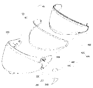
[0019] Fig. 2 is an exploded perspective view of a shield in
accordance with the embodiment of the present disclosure.
[0020] As depicted in Fig. 2, the shield 20 in accordance
with the embodiment of the present disclosure may include a
lens unit 100 positioned to face a front side of the front
opening of the helmet; a frame unit 200 provided along a
circumference of the lens unit 100; a ventilation unit 300
for communication between the inside and outside of the
shield 20; and a heat transfer unit 400 for preventing
condensation on a surface of the lens unit 100.
[0021] The lens unit 100 may be positioned to face the front
side of the front opening of the helmet. The lens unit 100
may be made of a transparent material in order for a helmet
wearer to obtain a view. The lens unit 100 may have a non-
uniform thickness throughout the lens unit 100. By way of
example, the lens unit 100 may be the thickest in a central
region and may become thinner in a direction toward an edge
- 6 -
CA 02746360 2011-07-14
thereof. In this case, distortion of light passing through
the lens unit 100 can be reduced.
[0022] The lens unit 100 may include, but is not limited to,
double lenses as depicted in Fig. 2, and may include one
single lens or multiple lenses. Further, the lens unit 100
in accordance with the embodiment of the present disclosure
may be protruded from the frame unit 200 toward the front of
the shield 20 by a certain length. The lens unit 100 will
be explained in detail by reference to Figs. 4A and 4B.
[0023] The frame unit 200 may be provided along the
circumference of the lens unit 100. The frame unit 200 may
provide a frame for coupling the lens unit 100 to the helmet
main body 10, and may be configured as one single body with
the lens unit 100. Therefore, the frame unit 200 may be
made of, but not limited to, a transparent material in the
same manner as the lens unit 100.
[0024] The frame unit 200 in accordance with the embodiment
of the present disclosure may include a subordinate device
to support the lens unit 100. By way of example, the frame
unit 200 may include a part of the ventilation unit 300 for
communication between the inside and outside of the shield
20 and may include a part of the heat transfer unit 400 for
preventing condensation on the lens unit 100.
[0025] The ventilation unit 300 may be configured for
communication between the inside and outside of the shield
20 and will be explained in detail by reference to Figs. 2
- 7 -
CA 02746360 2011-07-14
and 3A to 3C.
[0026] Figs. 3A to 3C are provided to explain a ventilation
unit of the shield in accordance with the embodiment of the
present disclosure.
[0027] The ventilation unit 300 may be provided at both
sides of the lens unit 100. The ventilation unit 300 may be
positioned to be connected to both sides of the lens unit
100 or may be provided at a certain distance from the lens
unit 100. Further, the ventilation unit 300 may be of
multiple devices functioning the same.
[0028] The ventilation unit 300 may include a ventilation
hole 320 and a guide unit 340. The guide unit 340 is
configured to cover a ventilation hole 320.
[0029] The ventilation hole 320 may be formed by removing a
part of the shield 20. The inside and outside of the shield
20 may be communicated with each other through the
ventilation hole 320. The ventilation hole 320 may be
formed at a certain position in a certain shape. Desirably,
the ventilation hole 320 may be formed so as not to prevent
an air flow between the inside and outside of the shield 20.
The ventilation hole 320 may be formed by etching the
equipped shield 20 or by injection-molding the shield 20
having the ventilation hole 320.
[0030] The ventilation hole 320 in accordance with the
embodiment of the present disclosure may be formed such that
at least a part of the ventilation hole 320 faces a rear
- 8 -
CA 02746360 2011-07-14
outside of the shield 20. By way of example, if the lens
unit 100 protrudes from the frame unit 200 toward the front
of the shield 20, the ventilation hole 320 may be formed by
consecutively removing a part of the lens unit 100 and a
part of the frame unit 200 at a boundary between the lens
unit 100 and the frame unit 200. A part of the ventilation
hole 320 formed by removing a side of the lens unit 100 may
be formed so as to face the rear outside of the shield 20
and another part of the ventilation hole 320 formed by
removing the part of the frame unit 200 may be formed so as
to face a vertical direction. If the ventilation hole 320
is formed so as to face the rear outside of the shield 20,
the helmet wearer may not be influenced by wind applied to
the front of the shield 20, and air inside the shield 20 can
flow out of the shield 20 smoothly.
[0031] The guide unit 340 may be coupled to an outer surface
of the shield 20 in an outside direction of the ventilation
hole 320. To be specific, the guide unit 340 may include a
cover unit 350 provided at a distance from the ventilation
hole 320 to cover the ventilation hole 320 and a guide hole
360 for communication between the ventilation hole 320 and
the rear outside of the shield 20. The guide unit 340 may
be coupled to the frame unit 200 by one or more fixing rings
370.
[0032] The cover unit 350 may serve as a main body of the
guide unit 340, and may be connected to the frame unit 200
- 9 -
CA 02746360 2011-07-14
and the lens unit 100. The cover unit 350 may include frame
unit connectors 352 provided at its upper side and lower
side for connection to the frame unit 200. The frame unit
connectors 352 may be formed in a predetermined support
shape so as to keep the guide unit 340 away from the shield
20. The frame unit connectors 352 may be of, but not
limited to, a uniform height. Further, the frame unit
connectors 352 may support the cover unit 350 and also may
subserve communication of the ventilation hole 320 in a
predetermined direction. If the air inside the shield 20
flows out of the shield 20 through the ventilation hole 320,
the air flow may be blocked so as not to flow out in an
upward or downward direction of the cover unit 350.
[0033] The cover unit 350 may include a lens unit connector
354 for connection to the lens unit 100. The lens unit
connector 354 may be connected to a side edge of the lens
unit 100. If the lens unit 100 protrudes as depicted in
Figs. 3A to 3C, the lens unit connector 354 may be not
necessarily formed in a support shape. However, if the lens
unit 100 does not protrude, the lens unit connector 354 may
be formed to have a certain height in the same manner as the
frame unit connectors 352. The lens unit connector 354 may
support the cover unit 350 by connection to the lens unit
100. Further, in the same manner as the frame unit
connectors 352, the lens unit connector 354 may block a flow
of the air inside the shield 20 flowed out through the
- 10 -
CA 02746360 2011-07-14
ventilation hole 320 for communication in a certain
direction.
[0034] The cover unit 350 in accordance with the embodiment
of the present disclosure may be formed so as to be extended
smoothly from the lens unit 100. In order to do so, the
lens unit connector 354 may have the same height as the lens
unit 100's side surface connected to the lens unit connector
354. Further, the lens unit connector 354 may have the same
width as the lens unit 100's side surface connected to the
lens unit connector 354. Since an air flow on an outer
surface of the shield 20 moves from the lens unit 100 toward
the guide unit 340, it is desirable to form the cover unit
350 to be extended smoothly from the lens unit 100 so as not
to block the air flow.
[0035] The guide hole 360 may be formed by opening an edge
of the cover unit 350, and may be limited by the frame unit
200 and the cover unit 350. The guide hole 360 may be
formed at a rear outside of the guide unit 340 for
communication of the ventilation hole 320 toward the rear
outside. A shape of the guide hole 360 may be determined by
the cover unit 350, and may be of any shape for easily
releasing the air inside the shield 20 to the outside of the
shield 20.
[0036] The guide unit 340 may include one or more fixing
rings 370 for coupling the guide unit 340 to the frame unit
200. The fixing ring 370 may be inserted into the
- 11 -
CA 02746360 2011-07-14
ventilation hole 320 and fixed thereto, or may be inserted
into a hole formed separately from the ventilation hole 320
and fixed thereto. In this case, the ventilation unit 300
may include a fixing hole 322 formed, separately from the
ventilation hole 320, by removing a part of the frame unit
200. Further, when the fixing ring 370 is inserted into the
fixing hole 322, the inserted fixing ring 370 may be screwed
by a screw or the like so as to be securely fixed to the
frame unit 200.
[0037] A width of the lens unit 100 may be narrower toward
its side edge. In the same manner, a width of the cover
unit 350 connected to the side surface of the lens unit 100
may be formed to be narrower toward the guide hole 360 in
order for air flowing outside the lens unit 100 to smoothly
flow through an upper end of the cover unit 350.
[0038] Hereinafter, the lens unit 100 will be explained in
detail by reference to Figs. 2, 4A and 4B.
[0039] Fig. 4A is a perspective view and Fig. 4B is a cross-
sectional view to explain a lens unit of a shield in
accordance with an embodiment of the present disclosure.
[0040] The lens unit 100 may include a first lens unit 120
configured as one single body with the frame unit 200 and a
second lens unit 140 coupled in an inside direction with
respect to the first lens unit 120. The second lens unit
140 may be coupled to the first lens unit 120 at a certain
distance from the first lens unit 120 so as to form an air
- 12 -
CA 02746360 2011-07-14
gap between the first lens unit 120 and the second lens unit
140.
[0041] The first lens unit 120 may be formed outside the
shield 20, and may be protruded from the frame unit 200
toward the front of the shield 20 in other embodiments of
the present disclosure. Desirably, the first lens unit 120
may be made of a transparent material. Further, desirably,
the first lens unit 120 may be made of a material averagely
thicker than a material of the second lens unit 140 in order
to resist an external force.
[0042] The second lens unit 140 may be coupled in the inside
direction with respect to the first lens unit 120. The
second lens unit 140 may be provided independently from the
frame unit 200, and may be antifog-treated. An antifog-
treatment is carried out to prevent the second lens unit 140
from being steamed due to humidity caused by the helmet
wearer's breathing. Further, the second lens unit 140 may
protect a rider's eyes by blocking direct sunlight from
getting into, the rider's eyes during the daytime. Further,
the second lens unit 140 may be made of plastic capable of
blocking light in order for the rider to obtain a clear view
despite strong sunlight or reflected light.
[0043] The second lens unit 140 may be made of a material
relatively thinner than that of the first lens unit 120.
Further, the second lens unit 140 may have identical or
similar size, shape, curve, transparency to those of the
- 13 -
CA 02746360 2011-07-14
first lens unit 120, but they may vary in other embodiments.
[0044] The second lens unit 140 may be coupled in the inside
direction of the first lens unit 120. The first lens unit
120 and the second lens unit 140 may be directly coupled to
each other by using a connecting member 480, or may be
indirectly coupled to each other by using a buffering member
as depicted in Figs. 4A and 4B.
[0045] A buffering member may be interposed between the
first lens unit 120 and the second lens unit 140, and may
support and connect the first lens unit 120 and the second
lens unit 140. The buffering member 160 may be provided
along a circumference of the first lens unit 120 and second
lens unit 140. The buffering member 160, the first lens
unit 120 and the second lens unit 140 may be securely
connected and fixed to one another by an adhesive material.
[0046] Desirably, the buffering member 160 in accordance
with the embodiment of the present disclosure may be made of
transparent or translucent material so as not to block a
helmet wearer's view. Further, desirably, the buffering
member 160 may be made of a compressible material. When the
second lens unit 140 is coupled to the inside of the first
lens unit 120 through the buffering member 160, if a vacuum
state is made between the first lens unit 120 and the second
lens unit 140 for a while, the connecting between the first
lens unit 120 and the second lens unit 140 can be more
securely maintained.
- 14 -
CA 02746360 2011-07-14
[0047] The connection between the first lens unit 120 and
the second lens unit 140 may form an air gap therebetween.
The air gap may be confined and sealed by the first lens
unit 120, the second lens unit 140 and the buffering member
160. A thickness of the air gap may be determined by a
height of the buffering member 160. As depicted in Fig. 4B,
desirably, the buffering member 160 may have a height that
does not allow the second lens unit 140 to block the
ventilation hole 320. If the buffering member 160 has a too
great height and blocks an inside surface of the ventilation
hole 320, it may be difficult for the air inside the shield
20 to be released to the outside of the shield 20.
[0048] The sealed air gap may maintain thermal
characteristics of the lens unit 100. By way of example, if
the temperature is low, the sealed air gap may prevent
condensation of steam on the surface of the lens unit 100.
[0049] Referring to Fig. 4B, the second lens unit 140 may be
positioned in an outside direction of the shield 20 as
compared with the frame unit 200. That is, the buffering
member 160 and the second lens unit 140 may be thinner than
the protruding first lens unit 120. In this case, the
ventilation hole 320 positioned at a side of the first lens
unit 120 may be provided along an inner surface of the
second lens unit 140. In this case, air flowing through the
second lens unit 140 can be released easily to the outside
of the ventilation hole 320.
- 15 -
CA 02746360 2011-07-14
[0050] Figs. 5A to 5C are provided to explain an air flow in
and out of a shield in accordance with an embodiment of the
present disclosure.
[0051] Generally, the shield 20 may have a shape curved in a
longitudinal direction in order to reduce air resistance.
When a helmet wearer drives, air outside the shield 20 may
move from side to side along a surface of the shield 20.
The air moving along the outer surface of the shield 20 may
be faster as it goes to the side.
[0052] According to Bernoulli's theorem, a fluid pressure
may be decreased when a fluid speed is high, and the fluid
pressure may be increased when the fluid speed is low.
[0053] Therefore, an air pressure at the side of the shield
20 may be lower than an air pressure inside the shield 20.
Thus, the air inside the shield 20 can be released to the
outside through the ventilation unit 300 provided at the
side of the shield 20.
[0054] Hereinafter, referring to Figs. 5A to 5C, an air flow
released through the ventilation unit 300 will be explained.
[0055] The air inside the shield 20 may move from side to
side along the second lens unit 140. Generally, the air
inside the shield 20 is generated by the helmet wearer's
breathing, and, thus, it may move from side to side along
the second lens unit 140. Particularly, since the second
lens unit 140 further protrudes toward the front of the
shield 20 as compared with the frame unit 200, the air
- 16 -
CA 02746360 2011-07-14
inside the shield 20 may move through an inner surface of
the second lens unit 140 rather than the frame unit 200.
[0056] Then, the air moving through the second lens unit 140
may pass through the ventilation hole 320. Since at least a
part of the ventilation hole 320 faces the rear outside of
the shield 20, the air moving through the second lens unit
140 may pass through the ventilation hole 320.
[0057] Thereafter, the air passing through the ventilation
hole 320 may pass through the guide hole 360. Since the
guide hole 360 is provided so as to face the rear outside,
the air passing through the guide hole 360 may meet with the
air outside the shield 20. The guide unit 340 may prevent
turbulence outside the ventilation hole 320 of the shield 20,
and, thus, the air released to the outside of the shield 20
cannot flow back to the inside of the ventilation hole 320.
Desirably, the guide hole 360 may be relatively narrower
than the ventilation hole 320 in order to easily release air.
[0058] If the inside and outside of the shield 20
communicate with each other, steam released by the helmet
wearer's breathing can be released easily to the outside of
the shield 20. Further, it is possible to prevent a helmet
wearer's view from being blocked by steam.
[0059] Figs. 6A to 6C are provided to explain a heat
transfer unit in accordance with the embodiment of the
present disclosure. Referring to Figs. 2, 6A, 6B and 6C,
the heat transfer unit 400 will be explained.
- 17 -
CA 02746360 2011-07-14
[0060] The shield 20 may include the heat transfer unit 400
for generating heat to prevent condensation on the surface
of the lens unit 100. If condensation occurs on the surface
of the lens unit 100, the helmet wearer may not obtain a
view. Therefore, the shield 20 may include the heat
transfer unit 400 for generating heat to prevent
condensation.
[0061] To be specific, the heat transfer unit 400 may
include, as depicted in Figs. 6A and 6B, a heat transfer
line 420 supplied with power and generating heat; a power
input unit 440 transferring power to the heat transfer line
420; and an electric wire 460 electrically connecting the
heat transfer line 420 with the power input unit 440.
[0062] The heat transfer line 420 may be provided in an
inner surface of the first lens unit 120 or in an outer
surface of the second lens unit 140, and one or more heat
transfer lines 420 may be provided at an edge along a
circumference thereof. In an embodiment, the heat transfer
line 420 may include a first heat transfer line 422 provided
at an upper edge of the first lens unit 120 or second lens
unit 140 along a circumference; and a second heat transfer
line 424 provided at an lower edge of the second lens unit
140. Desirably, the first heat transfer line 422 and the
second heat transfer line 424 may be provided inside the
buffering member 160. That is because the heat transfer
line 420 generates heat and the buffering member 160 may be
18 -
CA 02746360 2011-07-14
deformed or combusted due to overheating of the heat
transfer line 420. The heat transfer line 420 may prevent
condensation of steam on the surfaces of the first lens unit
120 and second lens unit 140 by generating heat.
[0063] The power input unit 440 may be provided on the frame
unit 200. The power input unit 440 may transfer power, and
may include, at its side, a power connector 444 to be
supplied with power from a power generation source. The
power generation source may be included in the helmet main
body 10. An end of the power connector 444 may be connected
to the power generation source and the other end may be
inserted into the power input unit 440 for transferring
power. The power connector 444 may be inserted into the
power input unit 440 in a rear outside direction of the
power input unit 440, but not limited thereto, in
consideration of air resistance. However, in other
embodiments, the shield 20 may not include the power input
unit 440, or may be configured as one single body with the
power input unit 440. Further, referring to Figs. 6A and 6B,
the power input unit 440 may be provided on the frame unit
200, but not limited thereto.
[0064] The frame unit 200 may further include a power input
connection unit 442 connected with the power input unit 440
as depicted in Fig. 2. The power input connection unit 442
may be protruded from the frame unit 200 toward the outside
by a certain length. Further, the power input connection
- 19 -
CA 02746360 2011-07-14
unit 442 may be provided at a certain distance from an upper
side of the lens unit 100, but not limited thereto.
[0065] A surface of the power input unit 440 in accordance
with the embodiment of the present disclosure may be
connected to the power input connection unit 442. The power
input connection unit 442 may include a hole for fixing the
power input unit 440. In this case, the power input
connection unit 442 may further include a clamping device
configured to pass through the inside and outside of the
hole. Thus, the power input connection unit 442 can
securely fix the connection between the power input unit 440
and the power input connection unit 442.
[0066] A surface of the power input unit 440 may be
connected to the electric wire 460 configured to transfer
power to the heat transfer line 420. After the power input
unit 440 is connected to the power input connection unit 442,
the electric wire 460 may be extended in an inside direction
of the first lens unit 120, such that a surface of the power
input connection unit 442 may further include a hole for
communication with the electric wire 460. The electric wire
460 may connect the power input unit 440 with the heat
transfer line 420 through the hole. Therefore, multiple
electric wires 460 may be provided depending on the number
of the heat transfer line 420. In the embodiment, the
electric wire 460 may include a first electric line 462 for
connecting the first heat transfer line 422 with the power
- 20 -
CA 02746360 2011-07-14
input unit 440; and a second electric wire 464 for
connecting the second heat transfer line 424 with the power
input unit 440. The power input unit 440 may be provided on
the frame unit 200, and the heat transfer line 420 may be
provided on an outer surface of the second lens unit 140.
Therefore, the power input connection unit 442 may include a
hole for a connection between the power input unit 440 and
the heat transfer line 420 in other embodiments as described
above. Further, desirably, the electric wire 460 may be
provided along an edge of the second lens unit 140 so as not
to block the helmet wearer's view. In the embodiment, the
electric wire 460 may be positioned between the buffering
member 160 and the heat transfer line 420.
[0067] The heat transfer unit 400 in accordance with the
embodiment of the present disclosure may include a
connecting member 480 configured to electrically connect the
electric wire 460 with the heat transfer line 420. The
connecting member 480 may be made of an insulating material
in order to connect an end of the electric wire 460 with an
end of the heat transfer line 420. Multiple connecting
members 480 may be provided depending on the number of the
heat transfer line 420. In the embodiment, the connecting
member 480 may include a first connecting member 482 for
connecting the first heat transfer line 422 with the first
electric wire 462; and a second connecting member 484 for
connecting the second heat transfer line 424 with the second
- 21 -
CA 02746360 2011-07-14
electric wire 464. The connecting member 480 may have a
certain shape for connecting the heat transfer line 420 with
the electric wire 460. In the embodiment, the connecting
member 480 may be provided so as to penetrate the second
lens unit 140. Further, the connecting member 480 may be
provided such that an end of the connecting member 480
connects the heat transfer line 420 provided on the second
lens unit 140 and an end of the electric wire 460.
[0068] The above description of the present disclosure is
provided for the purpose of illustration, and it would be
understood by those skilled in the art that various changes
and modifications may be made without changing technical
conception and essential features of the present disclosure.
Thus, it is clear that the above-described embodiments are
illustrative in all aspects and do not limit the present
disclosure. For example, each component described to be of
a single type can be implemented in a distributed manner.
Likewise, components described to be distributed can be
implemented in a combined manner.
[0069] The scope of the present disclosure is defined by the
following claims rather than by the detailed description of
the embodiment. It shall be understood that all
modifications and embodiments conceived from the meaning and
scope of the claims and their equivalents are included in
the scope of the present disclosure.
- 22 -