Note: Descriptions are shown in the official language in which they were submitted.
CA 02746945 2011-06-14
WO 2010/071648 PCT/US2008/087396
TITLE OF THE INVENTION
KEYLESS COUPLING ARRANGEMENT
BACKGROUND OF THE INVENTION
Field of the Invention
[0001] The present invention relates to a keyless coupling arrangement for
sliding two
parts together to form a single unit.
Description of Related Art
[0002] While the discussion hereinafter will make reference to construction
equipment,
such equipment is also referred to as demolition equipment, scrap handling
equipment, and
the like. The description of construction equipment is not intended to be
restrictive of the
equipment being referenced. Demolition equipment, such as heavy-duty metal
cutting shears,
plate shears, claws, hammers, buckets, grapples, and concrete crushers have
been mounted on
backhoes powered by hydraulic cylinders for a variety of jobs in the
demolition field. This
equipment provides for the efficient cutting and handling of scrap. For
example, in the
dismantling of an industrial building, metal scrap in the form of various
diameter pipes,
structural I-beams, channels, angles, sheet metal plates, and the like, must
be efficiently
severed and handled by heavy-duty metal shears. Such metal shears can also be
utilized for
reducing automobiles, truck frames, railroad cars, and the like. The shears
must be able to
move and cut the metal scrap pieces regardless of the size or shape of the
individual scrap
pieces and without any significant damage to the shears. In the demolition of
an industrial
building, concrete crushing devices, such as a concrete pulverizer or concrete
cracker, are
also used to reduce the structure to manageable components which can be easily
handled and
removed from the site. A grapple is often utilized where handling of debris or
work pieces is
the primary function of the equipment. Historically, all of these pieces of
equipment
represent distinct tools having significant independent capitol costs.
[0003] Each of these tools utilizes a jaw set pivotal about a pivot axis. Each
of these jaw
sets may be subjected to forces developed or generated on the magnitude of
between less than
1 ton to more than 10,000 tons and, as a result, it is imperative that each of
the jaws in the jaw
set is fabricated, shaped, or cast to withstand such forces. However, certain
jaw set designs
may preferably require a portion of the jaw set to be disassembled in order to
capture the
pivot shaft between the lower jaw and the upper jaw. In the past, such a
coupling
arrangement was achieved by sliding the hub into the anvil and then inserting
removable keys
1
CA 02746945 2011-06-14
WO 2010/071648 PCT/US2008/087396
along the direction of insertion/removal to secure the anvil and the hub
relative to one
another. While this adequately secured the hub within the anvil, it is a
relatively labor intense
practice and, furthermore, the stress forces produced by this coupling tend to
be concentrated
within the keys such that there is not an equal stress distribution over the
anvil and the hub.
[00041 A design is needed to slideably secure a hub within an anvil, whereby
the design is
relatively simple but, at the same time, eliminates the need for keys and
provides effective
redistribution of the stresses, such that localized forces are reduced and the
stresses overall
are more evenly distributed among the unified hub/anvil.
SUMMARY OF THE INVENTION
[00051 One embodiment of the invention is directed to a dovetail coupling
arrangement for
securing two removable parts along a coupling axis which are supporting
segments of a shaft
having a shaft axis. The coupling arrangement is suited to resist
translational forces
orthogonal to the coupling axis and has a first part having a receiver
extending along the
coupling axis, wherein the coupling axis is parallel to the shaft axis and,
wherein the receiver
has an inner wall with a receiver wall. The arrangement also has a second part
with a
projection extending along the coupling axis and an outer wall with a
projection wall profile.
A substantial portion of the outer wall of the projection corresponds to the
inner wall of
receiver, such that the projection mates with the receiver with a slip fit.
The receiver and the
projection define mating interlocking walls along the coupling axis to
restrict movement of
the projection within the receiver along directions orthogonal to the coupling
axis.
[00061 A second embodiment of the invention is directed to a dovetail coupling
arrangement for securing two removable parts along a coupling axis, wherein
the coupling
arrangement is suited to resist translational forces orthogonal to the
longitudinal axis. The
arrangement has a first part with a receiver extending along the coupling
axis, wherein the
receiver has an inner wall with a receiver wall. The arrangement also has a
second part with
a projection extending along the coupling axis and an outer wall with a
projection wall. A
substantial portion of the outer wall of the projection corresponds to the
inner wall of receiver
such that the projection mates with the receiver with a slip fit. The receiver
and the
projection define mating interlocking walls along the coupling axis to
restrict movement of
the projection within the receiver along directions orthogonal to the coupling
axis. A
removable shaft extends within the first part and the second part. The shaft
is oriented in a
direction generally orthogonal to the longitudinal axis to prevent relative
movement between
the first part and the second part along the coupling axis.
2
CA 02746945 2011-06-14
WO 2010/071648 PCT/US2008/087396
BRIEF DESCRIPTION OF THE DRAWINGS
[00071 Fig. I is a perspective view of a hydraulically operated jaw utilizing
a hub and anvil
in accordance with the subject invention;
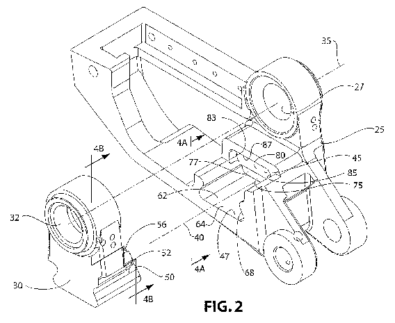
10008] Fig. 2 is an exploded perspective view of the hub and anvil in
accordance with the
subject invention;
[00091 Fig. 3 is a different exploded perspective view of the hub and anvil in
accordance
with the subject invention;
[0010] Fig. 4A is a view of a section of the anvil along arrows 4A 4A in Fig.
2;
[00111 Fig. 4B is a cross-section view of the hub along arrows 4B-4B in Fig.
2;
[00121 Fig. 5 is an exploded perspective view similar to Fig. 2 but with
securement bolts
included;
10013] Fig. 6 is an exploded perspective view similar to Fig. 3 but with
securement bolts
included;
[00141 Fig. 7A is a view of a section of the anvil along arrows 7A-7A in Fig.
5;
[00151 Fig. 7B is a cross-section view of the hub along arrows 7B-7B in Fig.
5;
[0016] Fig. 8A is an exploded cross-sectional view of the assembled hub/anvil
along the
plane defined by arrows 8A-8A in Fig. 5; and
[00171 Fig. 8B is an assembled view of the arrangement illustrated in Fig. 8A.
DESCRIPTION OF THE PREFERRED EMBODIMENTS
[00181 For purposes of explaining the subject invention, an attachment 5 used
for
demolition may be associated with a hydraulic excavator (not shown) and
includes a pair of
movable jaws 10, 11 which pivot about a main shaft 15. In operation of the
embodiment
illustrated in Fig. 1, the jaw 11 and the jaw 10 pivot toward one another,
such that the tip 13
of jaw I I passes through the opening 14 of jaw 10.
[0019] Jaw I1 includes a jaw portion 17 having a bore extending therethrough,
which
pivots about the main shaft 15. Furthermore, jaw 10 includes a jaw portion 19
and a jaw
portion 21 which also have a bore (not shown) extending therethrough pivoting
about the
main shaft 15.
[00201 Generally speaking, the main shaft 15 and the jaw 10 and jaw 11
pivoting
thereabout define a jaw set 23.
[00211 Fig. 1 illustrates a heavy-duty metal cutting shear, whereby the jaw
set 23 is made
up of a jaw 11, which has a tip 13 that passes through the opening 14 of jaw
10 when the jaws
3
CA 02746945 2011-06-14
WO 2010/071648 PCT/US2008/087396
10, 11 are closed. While this is one type of jaw set 23, it should be
appreciated that other jaw
sets exist, and the subject invention may be applied to these jaw sets as
well. In particular,
the subject invention may be applied to jaw sets associated with concrete
crushers, where the
two opposing jaws have tips that abut with one another when the jaws come
together or
associated with grapples, which have two opposing jaws, each with tines that
interlock with
one another when the jaws come together. Overall, any discussion of jaw sets
should not be
limited to the functions of a particular jaw set, but should focus upon the
arrangement by
which the two opposing jaws are connected.
[0022] In order to assemble or disassemble the jaw set 23, it may preferably
be necessary
to disassemble the jaw 10. In particular, the jaw 10 is comprised of an anvil
25 and a hub 30
that is secured within the anvil 25. It is this coupling arrangement between
the anvil 25 and
the hub 30 to which the subject invention is directed.
[0023] Although the following discussion will be directed to the hub 30
secured within the
anvil 25 in the context of a jaw set 23 associated with demolition equipment
5, it should be
appreciated that this coupling arrangement has a wide range of applications
and, therefore,
should not be limited to the particular application discussed herein.
[0024] Figs. 2 and 3 illustrate exploded views of the hub 30 relative to the
anvil 25, which
are shown in their assembled state in Fig. 1,
[0025] For ease in understanding this configuration, Figs. 2, 3, 4A, and 4B
will be
discussed together.
[0026] As mentioned, the subject invention is directed to a coupling
arrangement for
removably securing the hub 30 within the anvil 25. At least with respect to
this arrangement,
the hub 30 has a bore 32 extending therethrough and the anvil 25 has a bore 27
extending
therethrough along a shaft axis 35. The hub 30 slides within the anvil 25
along a coupling
axis 40. The coupling arrangement is suited to resist translational forces
orthogonal to the
coupling axis 40.
[0027] The anvil 25 has a receiver 45 extending along the coupling axis 40. As
illustrated
in Figs. 2 and 3, the coupling axis 40 may be parallel to the shaft axis 35.
The receiver 45 has
an inner wall 47 with a receiver wall profile. The hub 30 has a projection 50
extending along
the coupling axis 40 and an outer wall 52 with a projection wall profile. A
substantial portion
of the outer wall 52 of the projection 50 corresponds to the inner wall 47 of
the receiver 45,
such that the projection 50 mates with the receiver 45 with a slip fit. The
receiver profile and
the projection profile define mating interlocking walls 47, 52 along the
coupling axis 40 to
4
CA 02746945 2011-06-14
WO 2010/071648 PCT/US2008/087396
restrict movement of the projection 50 within the receiver 45 along directions
orthogonal to
the coupling axis 40.
[0028] Directing attention to Figs. 4A and 413, when viewed along the coupling
axis 40
from the end of the projection 50 (along arrows 4B-4B), the profile of the
projection 50 has a
dovetail shape (Fig. 4B) with a bottom outer surface 54 and a primary outer
top surface 56.
The bottom outer surface 54 and the primary top outer surface 56 are connected
by opposing
outer angled walls 58, 60. On the other hand, the receiver 45 has an open
section 62 with an
inner bottom surface 64 and opposed inner angled walls 66, 68 extending
upwardly
therefrom, such that when the anvil 25 and the hub 30 are mated, the bottom
outer surface 54
and the outer angled walls 58, 60 of the projection 50 are engaged with the
inner bottom
surface 64 and the inner angled walls 66, 68 of the receiver 45.
[00291 As seen from an inspection of Figs. 4A and 4B, the outer angled walls
58, 60 of the
projection 50 and the inner angled walls 66, 68 of the receiver 45 extend
upwardly and
inwardly at a dovetail angle X of between 40 and 70 degrees, with respect to a
line 70. The
line 70 extends perpendicular to the outer bottom surface 54 of the projection
50 and the
inner bottom surface 64 of the receiver 45. In a preferred embodiment, the
dovetail angle X
is approximately 57 degrees.
[00301 The receiver 45, in a region adjacent to the open section 62, further
includes a
primary enclosed section 75 formed with the inner bottom surface 64 and the
opposing inner
angled walls 66, 68 common with the open sections 62 and, additionally,
includes a primary
inner top surface 77 connecting the inner angled walls 66, 68, thereby mating
the anvil 25
with the hub 30. Additionally, the primary outer top surface 56 of the
projection 50 is
engaged with the primary inner top surface 77 of the receiver 45.
[00311 As illustrated in Figs. 2, 3, 4A, and 413, the receiver 45 further
includes, along at
least a portion of depth of the receiver 45, a secondary enclosed section 80
formed by the
inner bottom surface 64 and the inner opposing angled walls 66, 68 with the
open section 62
and additionally includes opposing inner extension walls 83, 85 extending from
the dovetail
shape of the receiver 45 and connected by a secondary inner top surface 87.
The profile of
the projection 50 further includes matching opposing outer extension walls 90,
92 extending
upwardly from the dovetail shape of the projection 50 and connected by a
secondary outer
top surface 94, such that when the anvil 25 and the hub 30 are mated, the
opposing inner
extension walls 83, 85 and the secondary inner top surface 87 of the receiver
50 mate with the
opposing outer extension walls 90, 92 and the second outer top surface 94 of
the projection
50.
CA 02746945 2011-06-14
WO 2010/071648 PCT/US2008/087396
[0032] The open section 62 of the receiver 45 may further include inner
horizontal
segments 97, 99 extending from the dovetail shape and, wherein the projection
50 further
includes outer horizontal segments 100, 102 extending from the outer dovetail
shape of the
projection, such that when the anvil 25 is mated with the hub 30, the inner
horizontal surface
97 and inner horizontal surface 99 rest upon the outer horizontal surface 100,
102,
respectively.
[0033] As illustrated in Figs. 4A and 4B, the multitude of inner surfaces
associated with
the receiver 45 and outer surfaces associated with the projection are
connected to adjacent
surfaces with transition segments that are curved to eliminate sharp edges
that may increase
stress concentrations.
[0034] So far discussed have been the surfaces between the receiver 45 and the
projection
50 that prevent translation in a direction orthogonal to the coupling axis 40.
However, it is
also necessary to restrain the hub 30, with respect to the anvil 25, in the
direction of the
coupling axis 40, even though the primary force is experienced by the
anvil/hub assembly
will be in a direction different than that of the coupling axis 40.
[0035] Directing attention to Figs. 5, 6, 7A, and 7B, to secure the hub 30
within the anvil
25 along the coupling axis 40, one or more bolts 105a, 105b, 105c extend
through the inner
bottom surface 64 through bores 107a, 107b, 107c and into matching bores 109a,
109b, 109c,
which are threaded, extending into the outer bottom surface 54 of the hub 30
to secure the
hub 30 within the anvil 25 along the coupling axis 40. As illustrated in Fig.
5, the bolt 105a
may further include a sleeve 110a which extends through the bore 107a of the
anvil 25 and
into an enlarged diameter portion of the bore 109a of the hub 30 so that any
shear loads
produced between the hub 30 and the anvil 25 will be absorbed by the sleeve
110a, which has
a greater cross-sectional area than the bolt 105a associated therewith. The
bore 109a has an
enlarged diameter portion 112a adjacent to the outer bottom surface 54 to
accommodate the
sleeve 110a. This enlarged diameter is not threaded. The threaded portion of
the bore 109a
begins beyond the enlarged diameter portion 112a. In addition to providing
additional cross-
sectional area to absorb shear forces, the sleeve 110a is also used to
properly align the hub 30
within the anvil 25 prior to securing the bolts 105a, 105b, 105c within their
respective bores
109a, 109b, 109c. Once secured within their respective bores, the bolts 105b,
105c and the
sleeve 110a absorb shear forces but, furthermore, the bolts 105a, 105b, 105c
retain the outer
bottom surface 54 of hub 30 against the inner bottom surface 64 of the anvil
25 to minimize
any twisting of the hub 30 within the anvil 25.
6
CA 02746945 2011-06-14
WO 2010/071648 PCT/US2008/087396
[00361 Additionally, to secure the hub 30 within the anvil 25, bolts 116a,
116b, 1160, 116d
extend through bores 117a, 117b, 117c, 117d within the anvil 25 and into
threaded bores
118a, 118b, 118c, 118d within the hub 30. Sleeves 121a, 121b, associated with
bolts 116a,
116b, fit within enlarged diameter portions 122a, 122b extending inwardly into
the threaded
bores 118a, 118b and with bolts 116c and 116d to provide additional cross-
sectional area to
resist shear forces in a direction perpendicular to the coupling axis 40.
Furthermore, all of the
bolts 116a, 116b, 116c, 116d pull the front wall 119 of the hub 30 against the
back wall 123
of the receiver 45 to provide additional stability to the projection
50/receiver 45 coupling.
[00371 In order to disassemble the hub 30 from the anvil 25, it is necessary
to push the
projection 50 of the hub 30 from the receiver 45 of the anvil 25. To achieve
this, an ejection
bolt 114 (Figs. 5, 8A, 8B) extends through a threaded bore 115 through the
back wall 123 of
the receiver 45. The threaded bore 115 is aligned with the front wall 119 of
the projection 50.
With all of the bolts 105a, 105b, 105c, 116a, 116b, 116c, 116d and all of the
sleeves I IOa,
121a, 121b removed from their respective bores, the ejection bolt 114 may be
advanced
within the threaded bore 115 against the front wall 119 of the projection 30
to urge the
projection 50 from the receiver 45, thereby separating the hub 30 from the
anvil 25.
[0038] As mentioned, the projection 50 has a front wall 119 and the receiver
has a back
wall 123, wherein the receiver back wall 123 and the projection front wall 119
face one
another. While what has been described is the ejection bolt 114 acting against
the front wall
119 of the projection 50, it is entirely possible for the ejection bolt 114 to
extend through the
hub and act upon the back wall 123 of the receiver 45.
[00391 The embodiments so far discussed are directed to a single hub 30 with a
projection
50. The projection 50 is mounted within a receiver 45 of an anvil. It should
be understood
that more than one hub may be mounted to a single anvil. As an example, and
directing
attention to Fig. 5, it is possible to form an additional receiver on the
opposite side of the
anvil 25 to accept a projection 50 on the opposite side of the anvil 25. Under
the
circumstances, more than one hub may be mounted upon a single anvil.
[00401 While specific embodiments of the invention have been described in
detail, it will
be appreciated by those skilled in the art that various modifications and
alternatives to those
details could be developed in light of the overall teachings of the
disclosure. The presently
preferred embodiments described herein are meant to be illustrative only and
not limiting as
to the scope of the invention which is to be given the full breadth of the
appended claims and
any and all equivalents thereof
7