Language selection

Search

Patent 2746949 Summary

Third-party information liability

Some of the information on this Web page has been provided by external sources. The Government of Canada is not responsible for the accuracy, reliability or currency of the information supplied by external sources. Users wishing to rely upon this information should consult directly with the source of the information. Content provided by external sources is not subject to official languages, privacy and accessibility requirements.

Claims and Abstract availability

Any discrepancies in the text and image of the Claims and Abstract are due to differing posting times. Text of the Claims and Abstract are posted:

  • At the time the application is open to public inspection;
  • At the time of issue of the patent (grant).
(12) Patent: (11) CA 2746949
(54) English Title: LIQUID RING PUMP WITH GAS SCAVENGE DEVICE
(54) French Title: POMPE A ANNEAU LIQUIDE DOTEE D'UN DISPOSITIF DE RECUPERATION DE GAZ
Status: Expired and beyond the Period of Reversal
Bibliographic Data
(51) International Patent Classification (IPC):
  • F04C 19/00 (2006.01)
(72) Inventors :
  • BISSELL, DOUGLAS ERIC (United States of America)
(73) Owners :
  • GARDNER DENVER NASH, LLC
(71) Applicants :
  • GARDNER DENVER NASH, LLC (United States of America)
(74) Agent: BORDEN LADNER GERVAIS LLP
(74) Associate agent:
(45) Issued: 2016-10-18
(86) PCT Filing Date: 2008-12-18
(87) Open to Public Inspection: 2010-06-24
Examination requested: 2013-11-27
Availability of licence: N/A
Dedicated to the Public: N/A
(25) Language of filing: English

Patent Cooperation Treaty (PCT): Yes
(86) PCT Filing Number: PCT/US2008/087439
(87) International Publication Number: US2008087439
(85) National Entry: 2011-06-14

(30) Application Priority Data: None

Abstracts

English Abstract


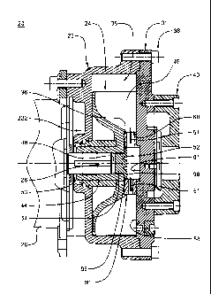
A liquid ring pump having a channel including a first opening
which opens into a first bucket formed by rotor blades. The first opening
is located along an arcuate path between a closing edge of an inlet port
and a leading edge of a discharge port The inlet port and discharge port are
in a port plate of the liquid ring pump. The channel has a second opening
which opens into a second bucket formed by rotor blades The second
opening is on an arcuate path between a closing edge of the discharge port
and a leading edge of the inlet port. A fluid pathway interconnects the first
and second openings. At least a portion of the liquid ring pump forming
the channel is disposed in a circumferential cylindrical cavity, wherein the
cavity is formed from a plurality of axially extending rotor blade ends.


French Abstract

L'invention concerne une pompe à anneau liquide dotée d'un canal comprenant une première ouverture qui s'ouvre dans un premier compartiment formé par des pales de rotor. La première ouverture est située le long d'un chemin arqué entre le bord arrière d'une lumière d'admission et le bord avant d'une lumière de refoulement. La lumière d'admission et la lumière de refoulement se situent dans une plaque perforée de la pompe à anneau liquide. Le canal comprend une seconde ouverture qui s'ouvre dans un second compartiment formé par des pales de rotor. La seconde ouverture se situe sur un chemin arqué, entre le bord arrière de la lumière de refoulement et le bord avant de la lumière d'admission. Une voie de fluide relie entre elles les première et seconde ouvertures. Au moins une partie de la pompe à anneau liquide formant le canal est disposée dans une cavité cylindrique circonférentielle, la cavité étant formée d'une pluralité d'extrémités de pales de rotor s'étendant axialement.

Claims

Note: Claims are shown in the official language in which they were submitted.


CLAIMS:
1. A
channel formed in a liquid ring pump, said liquid ring pump comprising a
housing,
a port plate, a rotor, and a shaft said housing forms a housing cavity in
which said rotor is
disposed, said shaft extends into said cavity and into a bore formed in a hub
of said rotor, a
plurality of rotor blades of said rotor extend radially outward from said hub,
each of said rotor
blades have an end extending in the axial direction relative to said shaft,
said axially
extending ends form a circumferential cylindrical cavity, a plurality of
buckets are formed by
said plurality of rotor blades; said port plate is coupled to an open end, of
said housing, said
port plate has a discharge port and an inlet port each of which open into said
housing cavity,
said discharge port and said inlet port each have a leading edge and a closing
edge, a first
bucket of said plurality of said buckets between the closing edge of said
inlet port and leading
edge of said discharge port, a second bucket of said plurality of said buckets
is between said
closing edge of said discharge port and said leading edge of said inlet port;
said channel
formed in said liquid ring pump comprising:
a first opening which opens into said first bucket, said first opening is
between said
closing edge of said inlet port and said leading edge of said discharge port;
a second opening which opens into said second bucket, said second opening
between
said closing edge of said discharge port and said leading edge of said inlet
port;
a device that is separate from the rotor and the port plate and at least
partially defines
a fluid pathway and that interconnects said first and second openings of said
channel, wherein
said channel allows for the flow of gas from said second bucket to said first
bucket and further
is adapted to be isolated from and sealed off from said discharge port and
inlet port in said
port plate when said pump is in a running mode;
said first bucket comprised of a mixture of gas from said inlet port and said
channel
when said pump is in the running mode, said inlet port is the place from which
gas enters the
first bucket from said inlet port; and
6

a portion of the liquid ring pump forming the channel is disposed, at least
partially, in
said circumferential cylindrical cavity.
2. A channel formed in a liquid rind pump, said channel comprising:
a first opening which opens into a first bucket formed by adjacent rotor
blades of a
rotor of said liquid ring pump, said first opening is between a closing edge
of an inlet port of
said liquid ring pump and a leading edge of a discharge port of said liquid
ring pump;
a second opening which opens into a second bucket formed by adjacent rotor
blades of
said rotor, said second opening between a closing edge of said discharge port
and a leading
edge of said inlet port, the first and second openings formed in a port plate;
a fluid pathway at least partially formed in a device that is separate from
the rotor and
the port plate, the fluid pathway interconnecting said first and second
openings of said
channel,
said channel allows for the flow of gas from said second bucket to said first
bucket
and further is adapted to be isolated from and sealed off from said discharge
port and inlet
port in the port plate when said pump is in a running mode;
said first bucket comprised of a mixture of gas from said inlet port and said
channel
when said pump is in a running mode; and
a portion of the liquid ring pump forming the channel is disposed, at least
partially, in
a circumferential cylindrical cavity formed by rotor blades of said rotor.
3. A component of a liquid ring pump, said component comprising:
a first opening formed in said component;
a second opening formed in said component;
a fluid pathway interconnecting said first and second openings, and
7

wherein when said component of said liquid ring pump is installed in said
liquid ring
pump, said first opening opens into a first bucket formed by adjacent rotor
blades of a rotor of
said liquid ring pump, said first opening is between a closing edge of an
inlet port of said
liquid ring pump and a leading edge of a discharge port of said liquid ring
pump; and
wherein said second opening opens into a second bucket formed by adjacent
rotor
blades of said rotor, said second opening between a closing edge of said
discharge port and a
leading edge of said inlet port; and
wherein said fluid pathway allows for the flow of gas from said second bucket
to said
first bucket and further is adapted to be isolated from and sealed off from
said discharge port
and inlet port in a port plate when said pump is in a running mode;
said first bucket comprised of a mixture of gas from said inlet port and said
channel
when said pump is in a running mode; and
wherein when installed said component of said liquid ring pump is separate
from the
rotor and the port plate and is disposed, at least partially, in a
circumferential cylindrical
cavity formed by rotor blades of said rotor.
4. A component of a liquid ring pump, said component comprising:
a first opening formed in said component;
a second opening formed in said component;
a fluid pathway interconnecting said first and second openings which allows
for the
flow of gas from a second bucket to a first bucket formed by rotor blades of a
rotor of said
pump, and
wherein when said component of said liquid ring pump is installed in said
liquid ring
pump, a beginning point of said first opening or a point tangent to said first
opening is an
angle .beta. from a closing edge of an inlet port of said liquid rind pump,
and angle .beta. is greater
than or equal to an angle .alpha.;
8

wherein angle a is an included angle between successive rotor blades of said
rotor of
said liquid ring pump, and
wherein when said component of said liquid ring pump is installed in said
liquid ring
pump separate from the rotor, said second opening is within .gamma. angular
degrees in front of a
line, said line extending from a center point of a shaft of said liquid ring
pump to a point of
closest approach of a tip of a rotor blade to an internal surface of a housing
enclosing said
rotor blade, to .delta. angular degrees after said line, and .gamma. is
greater than or equal to .delta.; and
the fluid pathway is adapted to be isolated from and sealed off from a
discharge port
and the inlet port in a separate port plate when said component is installed
in said pump and
when said pump is in a running mode,
wherein a portion of the liquid ring pump forming the fluid pathway is adapted
to be
disposed at least partially, in a circumferential cylindrical cavity formed by
rotor blades of
said rotor when said component is installed in said pump.
5. A channel formed in a portion of a liquid ring pump, said channel
comprising:
a first opening formed in said liquid ring pump, a beginning point of said
first opening
or a point tangent to said first opening is an angle .beta. from a closing
edge of an inlet port of
said liquid ring pump, and .beta. is greater than or equal to an angle
.alpha., wherein angle .alpha. is an
included angle between successive rotor blades of a rotor of said liquid ring
pump;
a second opening formed in said liquid ring pump, said second opening is
within .gamma.
angular degrees in front of a line, said line extending from a center point of
a shaft of said
liquid ring pump to a point of closest approach of a tip of a rotor blade to
an internal surface
of a housing enclosing said rotor blade, to .delta. angular degrees after said
line, and .gamma. is greater
than or equal to .delta.; and
a fluid pathway interconnecting said openings, the fluid pathway is adapted to
be
isolated from and sealed off from a discharge port and the inlet port in a
separate port plate
when said pump is in a running mode,
9

wherein a device separate from the rotor and the port plate forms at least a
portion of
the channel and is disposed at least partially, in a circumferential
cylindrical cavity formed by
rotor blades of said rotor.
6. The component of claim 4, wherein the component is disposed, at least
partially, in
the circumferential cylindrical cavity formed by rotor blades of said rotor.
7. The component of claim 3, 4, or 6, wherein the component is a cylinder.
8. The component of claim 4 or 6, wherein the angle .gamma. and .delta. are
dependent on the
geometry of said rotor and the included angle .alpha..
9. The channel of claim 5, wherein the angle .gamma. and .delta. are
dependent on the geometry of
said rotor and the included angle .alpha..
10. The component of claim 4 or 6, wherein the angle y is less than or
equal to 20 degrees
and the angle .delta. is less than or equal to 10 degrees.
11. The channel of claim 5, wherein the angle .gamma. is less than or equal
to 20 degrees and the
angle .delta. is less than or equal to 10 degrees.
12. The channel of claim 1, 2, or 5, wherein the first opening is an
opening from a
discharge channel and the second opening is an opening from an inlet channel.
13. The channel of claim 12, wherein the discharge channel has a cross-
sectional area
greater than the cross-sectional area of the inlet channel.
14. The channel of claim 12, wherein the discharge channel has a cross-
sectional area
twice the cross-sectional area of the inlet channel.
15. The channel of claim 1, 2, or 5, wherein said inlet port is the only
inlet port in the port
plate and said discharge port is the only discharge port in the port plate.
16. The component of claim 3 or 4, wherein said inlet port is the only
inlet port in the port
plate and said discharge port is the only discharge port in the port plate.

17. The channel of claim 1, 2, or 5, wherein liquid ring pump has at least
two single
staged sections.
18. The component of claim 3 or 4, wherein said liquid ring pump has at
least two single
staged sections.
11

Description

Note: Descriptions are shown in the official language in which they were submitted.


CA 02746949 2011-06-14
WO 2010/071651 PCT/US2008/087439
LIQUID RING PUMP WITH GAS SCAVENGE DEVICE
FIELD OF INVENTION
[0001] The present invention relates to a liquid ring pump. More particularly,
the
invention relates to a channel which fluidly interconnects buckets of a rotor
of a liquid ring
pump.
BACKGROUND
[0002] Liquid ring pumps are well known. U.S. Patent No. 4,850,808, Schultze,
discloses such a liquid ring pump. The pump is conically ported (conical
liquid ring pump) and
has one or two stages. The pump includes a housing; a rotor assembly within
the housing; a
shaft extending into the housing on which the rotor assembly is fixedly
mounted; and a motor
assembly coupled to the shaft. During operation, the housing is partially
filled with operating
liquid so that when the rotor is rotating, the rotor blades engage the
operating or pumping liquid
and cause it to form an eccentric ring that diverges and converges in the
radial direction relative
to the shaft. Where the liquid is diverging from the shaft, the resulting
reduced pressure in the
spaces between adjacent rotor blades of the rotor assembly (buckets)
constitutes a gas intake
zone. Where the liquid is converging towards the shaft, the resulting
increased pressure in the
spaces between adjacent rotor blades (buckets) constitutes a gas compression
zone. A cone
shaped member is mated within a cone shaped bore of the rotor assembly. The
cone shaped
member is ported to allow gas that would otherwise be carried over from the
compression zone,
to bypass the intake zone and re-enter the compression zone.
[0003] U.S. Patent No. 4,251,190, Brown discloses a water ring rotary air
compressor.
The compressor includes a housing; a rotor assembly disposed within the
housing; a motively
powered shaft extending into the housing and fixedly coupled to the rotor
assembly. The rotor
assembly utilizes a pumping liquid and creates an eccentric ring in a manner
similar to U.S.
Patent No. 4,850,808. A port plate or head has a circumferential extension
extending into a
cylindrical bore of the rotor assembly. A port sleeve is disposed and press
fit around the
cylindrical extension. The sleeve includes a circumferential groove and a
plurality of
longitudinally extending slots. The sleeve reduces cavitation.
1

CA 02746949 2011-06-14
WO 2010/071651 PCT/US2008/087439
SUMMARY
[0004] It is advantageous to reduce complex machining and shimming associated
with
conical liquid ring pumps. Accordingly, the present invention provides a
channel in a portion of
a liquid ring pump. The channel has a first opening which opens into a first
bucket formed by
rotor blades. The first opening is located along an arcuate path between a
closing edge of an
inlet port and a leading edge of a discharge port. The inlet port and
discharge port are in a port
plate of the liquid ring pump.
[0005] The channel has a second opening which opens into a second bucket
formed by
rotor blades. The second opening is on an arcuate path between a closing edge
of the discharge
port and a leading edge of the inlet port. A fluid pathway interconnects the
first and second
openings. At least a portion of the liquid ring pump forming the channel is
disposed in a
circumferential cylindrical cavity, wherein the cavity is formed from a
plurality of axially
extending rotor blade ends. The portion of the liquid ring pump providing the
channel can be a
removable cylinder.
The channel is isolated and sealed off from the discharge port and the inlet
port of the
port plate when the pump is in the running mode. The invention is described.
The invention is
shown in the figures.
BRIEF DESCRIPTION OF THE DRAWINGS
[0006] FIG. 1 is an irregular partial sectional view taken parallel to the
shaft of a liquid
ring pump embodying the invention.
[0007] FIG. 2A is a perspective view of the cylinder in which the sealed
channel is
formed.
[0008] FIG. 2B is a right side plan view of the cylinder shown in figure 2A.
[0009] FIG. 2C is a front side plan view of the cylinder shown in figure 2A.
[00010] FIG. 2D is a sectional view taken along view lines 2D-2D of figure 2C.
[00011] FIG. 2E is a rear side plan view of the cylinder shown in figure 2A.
[00012] FIG. 3 is a schematic sectional representation taken perpendicular to
the shaft of
the liquid ring pump to highlight the relative position of the rotors,
operating liquid, inter-blade
spaces, inlet port, discharge port, and fluid pathway formed in the cylinder
when the pump is in
the running mode.
[00013] FIG. 4 is a front perspective view of the rotor shown in FIG. 1.
2

CA 02746949 2011-06-14
WO 2010/071651 PCT/US2008/087439
DETAILED DESCRIPTION
[00014] As can be seen with reference to FIGs. 1-4, liquid Ring Pump 20
includes an
annular housing 22, a rotor 24 within the housing, with a shaft 26 of driver
or prime mover 28
extending into the housing. The rotor 24 is fixedly mounted to shaft 26. The
housing 22 forms a
lobe which provides a cavity 36 in which rotor 24 and operating liquid 53 are
disposed. Port
plate 30 covers an open end of housing 22. The port plate has a gas inlet port
32 and a gas
discharge port 34 from which gas enters and exits spaces 49 formed by
successive or adjacent
rotor blades 46, said spaces referred to as buckets. Each bucket is sealed off
by the inner surface
of the operating liquid 53 when the pump is in the running mode. Thus the
buckets, when the
pump is in the running mode, are sealed buckets. Port plate 30 is secured to
housing 22 by way
of screws 38 or other appropriate means. A connection plate 40 is secured to
port plate 30 by
way of screws or other appropriate means. The housing at a closed end 222 is
secured to driver
28. In the shown example, driver 28 is a motor. Of course, the driver could be
an electric motor
or something other than a motor.
[00015] Rotor 24 includes a hub 44 from which rotor blades 46 extend. A
cylindrical bore
48 extends into the hub. Shaft 26, extending through housing bore 50, extends
into cylindrical
bore 48. In the embodiment shown in FIG. 1, the shaft has a free end oriented
towards port plate
30. The free end is adjacent plug 52. Plug 52 has a body 54 that is secured in
hub bore open end
56. The hub 44 is fixedly mounted to shaft 26.
[00016] Each rotor blade 46 has a free axial end 58 adjacent port plate 30,
which extends
in the radial direction relative to shaft 26. Each rotor blade 46 has a
horizontally extending free
end 60, extending in the axial direction relative to shaft 26. Each horizontal
free end 60 is
substantially parallel to shaft 26. The horizontal free ends 60 form a
circular cavity 62 defining a
circumference and do not form a conical cavity. Arrow 55 illustrates the
direction of rotation of
the rotor 24.
[00017] A device 64 is disposed between port plate 30 and rotor 24. Figure 1
shows
device 64 installed in the liquid ring pump 20. Device 64 is a component of
the liquid ring pump.
As seen in FIG. 2A-2E, device 64 is generally a circular cylinder. Device 64
has a circular bore
66 defined by counter bore 68. Device 64 has a circumferential surface 70 and
diameter 72.
Device 64 is sized to fit within circular cavity 62. There is a running
clearance between
circumferential surface 70 and horizontal free ends 60. The amount of
clearance depends upon
the pump volume and other known factors. Extending from a first end face 77 of
device 64 is a
circular collar, boss or ring 76 having a diameter smaller than diameter 72.
The circular collar
76 is a locating member to position the device 64 relative to plate 30. The
locating member
could be any number of structures. Device 64 has a second end face 78. The
second end face 78
3

CA 02746949 2011-06-14
WO 2010/071651 PCT/US2008/087439
has a flat recessed surface forming a circumferential recess 80. The recess 80
provides a passage
for lubrication. Device 64 has a gas discharge channel 82 and a gas inlet
channel 84. Gas
discharge channel 82 extends in the radial direction through a portion of
device 64 such that
channel 82 has a first opening 86 which opens into bore 66 through counter
bore 68; and a
second opening 88 which opens through circumferential surface 70. Channel 82'
joins openings
86 and 88. Thus, channel 82 comprises channel 82', 86, and 88. Gas inlet
channel 84 extends in
the radial direction through a portion of device 64 such that inlet channel 84
has an opening 90
which opens into bore 66 through counter bore 68. Inlet channel 84 also has an
opening 92
which opens through circumferential surface 70. Channel 84' joins openings 90
and 92. Thus,
channel 84 comprises channel 84', 90, and 92.
[00018] When device 64 is installed, the second end face 78 is oriented to
face away from
port plate 30 and towards the housing closed end 222. Second end face 78 is
near rotor hub end
face 96. The amount of clearance depends upon the pump volume and other known
factors.
Plug cover 98 fits within the bore 66.
[00019] The first end face surface 77 abuts against port plate 30. Collar 76
fits within
circumferential port plate recess 81 to seal off bore 66 at the first end face
surface 77. Device 64
is oriented so it fits within rotor cylindrical cavity 62 and so its diameter
is substantially
perpendicular to shaft 26. First end face surface 77 has one or more fastener
receiving through
holes 74 which receive fasteners to secure cylinder 64 to port plate 30.
[00020] As can be seen in FIG. 3, discharge channel 82 is circumferentially
located
between inlet port closing edge 32' and discharge port leading edge 34". The
position of
discharge channel 82 is determined by the geometry of rotor blade 46, the
angular spacing
between successive blades 46, and the position of inlet port closing edge 32'.
It is preferable that
the angle p between the closing edge 32' and a point tangent to or a point at
the beginning (point
B) of channel 82 be greater than the included angle a between successive
blades 46. Angle f3
can be equal to or greater than angle a
[00021] Inlet channel 84 is circumferentially located between discharge port
closing edge
34' and inlet port leading edge 32". The position of inlet channel 84 is
determined by the
geometry of the internal surface of housing 22, the geometry of rotor blade
46, the angular
spacing a between successive blades 46, the position of discharge port closing
edge 34', and the
position of inlet port leading edge 32". If a line 601 is constructed from the
shaft center (point
A) to the point of closest approach of the tip of rotor blade 46 to the
internal surface of housing
22 (point A' ), then channel 84 is preferably located within 20 angular
degrees (angle y) before
said line and 10 angular degrees (angle S) after said line, the variation
being dependent on the
geometry of the rotor 24 and included angle a.
4

CA 02746949 2011-06-14
WO 2010/071651 PCT/US2008/087439
[000221 In the running mode the channel comprised of bore 66, discharge
channel 82 and
inlet channel 84 is isolated and sealed off from discharge port 34 and inlet
port 32. Therefore,
device 64, when the pump is in the running mode, provides an isolated and
sealed channel 66,
82, 84. The sealing and isolation occurs because in the running mode, running
clearances, such
as the clearance between end face 78 and hub end face 96, are sealed by the
operating liquid. If
the pump is shut down and the operating liquid is absent, then the running
clearances would be
unsealed. In this case, device 64 could be considered to have a substantially
sealed and isolated
channel 66, 82, 84, i.e., sealed except for unsealed running clearances. As
can be seen in the
figures, channel 82', opening 86, bore 66, opening 90, and channel 84' form a
fluid pathway
interconnecting openings 88 and 92.
[000231 The sealed channel 66, 82, 84 allows gas 551, trapped in a sealed
bucket 49 which
has rotated to position 549, to escape from this bucket and be deposited in a
sealed bucket 49
which has rotated to position 449. Thus, gas 551 that would otherwise be
carried over from the
compression zone 100 to intake zone 102 is allowed to bypass intake zone 102
and re-enter
compression zone 100. This improves the pump's efficiency. Generally, the gas
551 flows in
the direction of arrows 51.
[000241 A bucket 49 is in position 549 when it has swept past port plate
discharge port
closing edge 34' but not yet begun to sweep by port plate inlet leading edge
32". A bucket 49 is
in position 449 when it has swept past port plate inlet closing edge 32' but
not yet begun to
sweep by port plate discharge port leading edge 34".
[000251 Though the invention has been described by reference to an example of
a single
stage liquid ring pump, the invention is equally applicable to two stage
liquid ring pumps or
pumps having two or more single staged sections. The above is only an example
of an
embodiment of the invention. There are other examples which would include
different
embodiments of the invention. For example, the exit of channel 66, 82', 84'
could be in the port
plate. The device can be integral or separable from the port plate.
Accordingly, many
modifications and variations in the present invention are possible in light of
the above teachings.
It is to be understood that within the scope of the appended claims, the
invention may be
practiced otherwise then as specifically described herein. The recitations in
the claims are to be
read inclusively.

Representative Drawing
A single figure which represents the drawing illustrating the invention.
Administrative Status

2024-08-01:As part of the Next Generation Patents (NGP) transition, the Canadian Patents Database (CPD) now contains a more detailed Event History, which replicates the Event Log of our new back-office solution.

Please note that "Inactive:" events refers to events no longer in use in our new back-office solution.

For a clearer understanding of the status of the application/patent presented on this page, the site Disclaimer , as well as the definitions for Patent , Event History , Maintenance Fee  and Payment History  should be consulted.

Event History

Description Date
Time Limit for Reversal Expired 2021-08-31
Inactive: COVID 19 Update DDT19/20 Reinstatement Period End Date 2021-03-13
Letter Sent 2020-12-18
Letter Sent 2020-08-31
Inactive: COVID 19 - Deadline extended 2020-08-19
Inactive: COVID 19 - Deadline extended 2020-08-06
Inactive: COVID 19 - Deadline extended 2020-07-16
Inactive: COVID 19 - Deadline extended 2020-07-02
Inactive: COVID 19 - Deadline extended 2020-06-10
Letter Sent 2019-12-18
Common Representative Appointed 2019-10-30
Grant by Issuance 2016-10-18
Inactive: Cover page published 2016-10-17
Pre-grant 2016-09-02
Inactive: Final fee received 2016-09-02
Notice of Allowance is Issued 2016-04-06
Letter Sent 2016-04-06
Notice of Allowance is Issued 2016-04-06
Inactive: QS passed 2016-03-30
Inactive: Approved for allowance (AFA) 2016-03-30
Amendment Received - Voluntary Amendment 2016-01-08
Inactive: S.30(2) Rules - Examiner requisition 2015-12-09
Inactive: Report - No QC 2015-12-09
Amendment Received - Voluntary Amendment 2015-07-31
Inactive: S.30(2) Rules - Examiner requisition 2015-02-03
Inactive: Report - No QC 2015-01-21
Amendment Received - Voluntary Amendment 2014-04-25
Amendment Received - Voluntary Amendment 2013-12-13
Letter Sent 2013-12-04
Request for Examination Requirements Determined Compliant 2013-11-27
All Requirements for Examination Determined Compliant 2013-11-27
Request for Examination Received 2013-11-27
Inactive: Correspondence - PCT 2011-09-28
Inactive: Cover page published 2011-08-23
Correct Applicant Requirements Determined Compliant 2011-08-05
Inactive: Notice - National entry - No RFE 2011-08-05
Application Received - PCT 2011-08-04
Inactive: IPC assigned 2011-08-04
Inactive: First IPC assigned 2011-08-04
National Entry Requirements Determined Compliant 2011-06-14
Application Published (Open to Public Inspection) 2010-06-24

Abandonment History

There is no abandonment history.

Maintenance Fee

The last payment was received on 2015-12-02

Note : If the full payment has not been received on or before the date indicated, a further fee may be required which may be one of the following

  • the reinstatement fee;
  • the late payment fee; or
  • additional fee to reverse deemed expiry.

Patent fees are adjusted on the 1st of January every year. The amounts above are the current amounts if received by December 31 of the current year.
Please refer to the CIPO Patent Fees web page to see all current fee amounts.

Owners on Record

Note: Records showing the ownership history in alphabetical order.

Current Owners on Record
GARDNER DENVER NASH, LLC
Past Owners on Record
DOUGLAS ERIC BISSELL
Past Owners that do not appear in the "Owners on Record" listing will appear in other documentation within the application.
Documents

To view selected files, please enter reCAPTCHA code :


To view images, click a link in the Document Description column. To download the documents, select one or more checkboxes in the first column and then click the "Download Selected in PDF format (Zip Archive)" or the "Download Selected as Single PDF" button.

List of published and non-published patent-specific documents on the CPD .

If you have any difficulty accessing content, you can call the Client Service Centre at 1-866-997-1936 or send them an e-mail at CIPO Client Service Centre.


Document
Description 
Date
(yyyy-mm-dd) 
Number of pages   Size of Image (KB) 
Description 2011-06-13 5 308
Claims 2011-06-13 4 169
Representative drawing 2011-06-13 1 40
Drawings 2011-06-13 4 108
Abstract 2011-06-13 1 71
Claims 2013-12-12 5 201
Claims 2014-04-24 5 205
Claims 2015-07-30 6 229
Claims 2016-01-07 6 215
Representative drawing 2016-09-19 1 20
Notice of National Entry 2011-08-04 1 194
Reminder - Request for Examination 2013-08-19 1 117
Acknowledgement of Request for Examination 2013-12-03 1 176
Commissioner's Notice - Application Found Allowable 2016-04-05 1 161
Commissioner's Notice - Maintenance Fee for a Patent Not Paid 2020-01-28 1 541
Courtesy - Patent Term Deemed Expired 2020-09-20 1 552
Commissioner's Notice - Maintenance Fee for a Patent Not Paid 2021-02-04 1 545
PCT 2011-06-13 2 87
Correspondence 2011-09-27 2 73
Amendment / response to report 2015-07-30 14 558
Examiner Requisition 2015-12-08 3 203
Amendment / response to report 2016-01-07 14 491
Final fee 2016-09-01 1 36